Reusing the Sony CRT Module of an HP 16500A Logic Analyzer
- Introduction
- Safety First
- The Sony CHM-9001-00 CRT Module
- CRT Display Signals according to the HP Service Manual
- The Hunt for the Sony CHM-9001-00 Service Manual
- Sony CHM-9001-00 Details
- Connecting the CRT to a VGA Port
- Dropping the Logic Analyzer Chassis for a Stand Alone Power Supply
- Going Forward…
- References
Introduction
In my previous blog post I disassembled an HP 16500A logic analyzer. There wasn’t much to it other than getting a look into a old dinosaur of a machine, but one thing that caught my attention was the CRT unit: unlike most other old CRT-based test equipment, such as my Tektronix TDS 420A oscilloscope, the CRT of HP 16500A is not an integral part of the machine, but it’s a self-contained module that can easily slide out of the main chassis and wired up independently. It’s a tiny little monitor!
It made me wonder if there’d be some to use it in some creative ways?
In this blog post, I try to do exactly that.
Safety First
Before proceeding, do youself a favor and (re)read the Safety First section of the teardown blog post. The voltage levels in a CRT are no joke, and even the 120V DC input voltage is high enough to warrant a serious amount of respect.
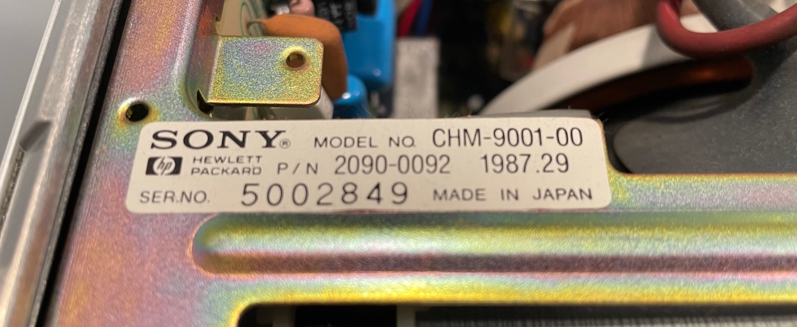
The Sony CHM-9001-00 CRT Module
The CRT is a Sony CHM-9001-00 with a 10” Trinitron tube and an active screen area of 9”.
The HP 16500A service manual is the obvious place to look for information, and there’s indeed a little bit there:
-
Section 4-2 instructs how to degauss the display.
Just press the degauss button at the back of the power supply.
-
Section 4-5 explains how to make adjustments to CRT beam convergence, geometry, and white balance.
It’s a quite heavy procedure, but these are usually once-and-done trimmer settings that should already be OK. The settings were fine on my 2 units.
-
Figures 6-19 and 6-20 have flowcharts from some CRT-related troubleshooting.
The remedies don’t go much further than suggesting to replace cables when an image doesn’t show…
-
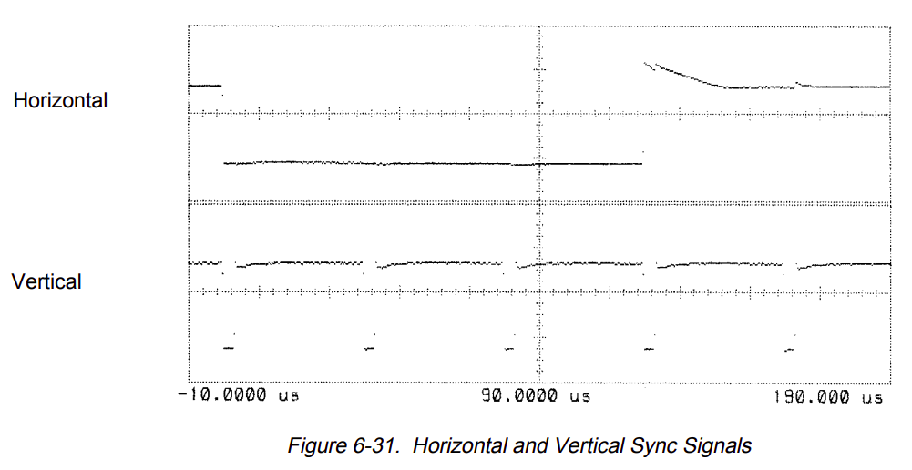
The Video Signals Check on page 6-34 finally has some meat: it lists the video related pin numbers on the 40-pin CRT flat cable, the expected voltage levels of the signals, and even a scope shot of the vertical and horizontal sync signals.
CRT Display Signals according to the HP Service Manual
Let’s have a closer look at the video signal details of page 6-34.
The pin numbers in the HP service manual are listed the table below, but they are wrong: HSYNC and VSYNC have been swapped:
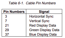
The signal types are pretty traditional:
- Horizontal sync (pin 7, not 3)
- Vertical sync (pin 3, not 7)
- 3 analog signals for RGB (pins 21, 29, and 37 for R, G and B resp.)
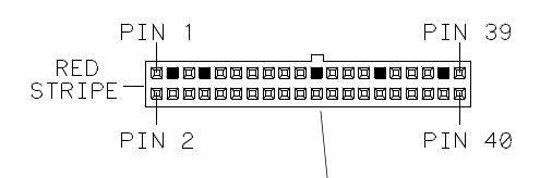
If you were wondering about the functionality of the remaining 35 pins of the 40 pin connector, wonder no more: they are either connected to ground or unused. Sony must have realized the idiocy of such a large connector for just 5 functional pins, because later members of the HP logic analyzer family have a similar CRT module with a much smaller connector.
The voltage levels for the sync signals are a standard 5V TTL (good!), but the voltage levels for the analog signals are weird, with a baseline of -1.7V and a maximum value of 125mV (WTF?), or an amplitude of 1.825V.
I was initially hopeful that it’d be easy to drive the CRT module with something that was similar to a standard PC VGA output, but the voltage levels above were not encouraging.
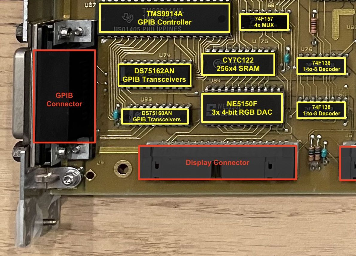
A good look at all the ICs on the main CPU controller board of the logic analyzer shows that the RGB signals are driven by an NE5150 triple 4-bit RGB DAC.
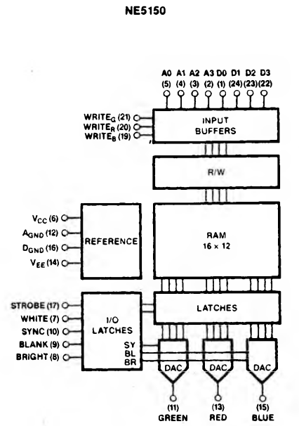
I already wrote about the digital aspects of the NE5150 in the teardown blog post, but let’s now have a closer look at the analog output characteristics.
The datasheet has the following to say:
The DACs include all the composite video functions to make the output waveforms meet RS-170 and RS-343 standards, and produce 1Vpp into 75 Ohm.
The following table goes more in detail:
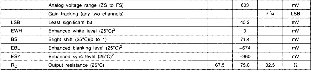
We’re seeing an enhanced sync level of -960mV and an enhanced white level of 0mV, for a total range of 960mV, exactly almost exactly half the 1.825V amplitude that’s listed in the 16500A service manual.
What’s happening here is that the voltage levels that are mentioned in the logic analyzer service manual are supposed to be measured on connector after it has been unplugged from the CRT module. The NE5150 has an output resistance of 75 Ohm. If the CRT module has a 75 Ohm input impedance as well, then the 1.825V on the connector will be divided in half!
The table also shows a voltage of -674mV for the enhanced blanking level. It doesn’t show the level of black, but that’s usually slightly above the blanking voltage. It’s safe to say that the amplitude from black to white will be on the order of ~700mV, which is right in line with the R/G/B values of a standard VGA cable.
The only remaining question is one of the negative voltage levels: VGA signalling only has positive voltage levels.
But what if there’s a series capacitor inside the CRT module that remove the DC level? In that case, only the amplitude of the RGB signals matter, not their value relative to ground!
The Hunt for the Sony CHM-9001-00 Service Manual
To really know all details of the CRT module, you need a service manual of the CRT unit itself. Google doesn’t turn up a lot of info, but eventually, I struck gold at sonyservicemanual.com which sells the service manual for $17.49 in the form of… a microfiche.
For those unfamiliar: a microfiche is a slide film on which a negative image of a document has been optically projected at greatly reduced size, usually by a factor 25. Multiple pages are stored in matrix format. It dates from way back when digital storage either didn’t exist or was too expensive.
Back then, to display a microfiche, you were supposed use a special reader like the Eyecom 1000 below:
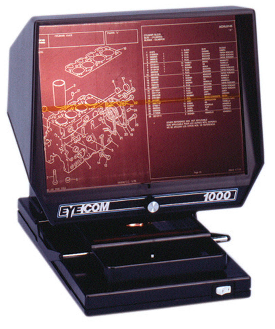
It has a glass plate on which your place the microfiche and a projector similar to old projection TVs that display the pages on a screen.
I had never used microfiches before and was intrigued. The price was still within reason, so I went for it. A few days later, I was the proud owner of the CHM-9001-00 service manual:
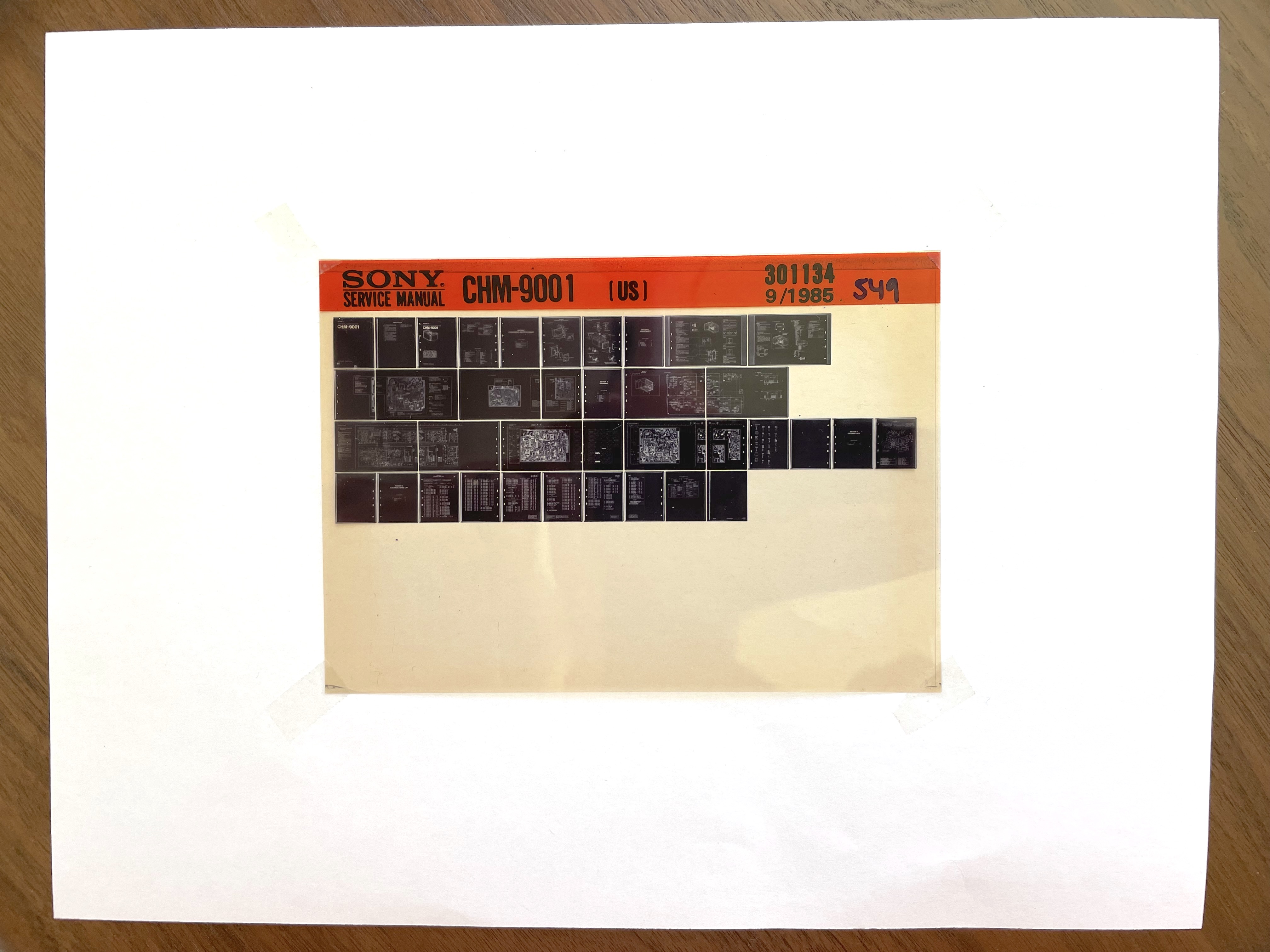
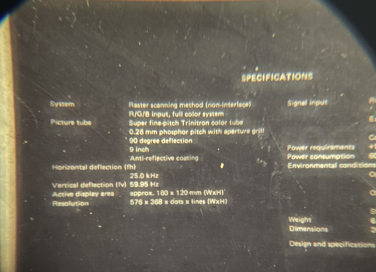
If you don’t have access to an Eyecom 1000, how do read such a thing in this day and age? I tried to photograph it with my lab microscope and an iPhone camera adapter. The result is not great, but it’s good enough to extract important information:
The focus of this photograph would have been much better if I had properly taped the microfiche on a piece a white paper.
We can at least see some important parameters:
- resolution: 576x368
- vertical scan rate: 60Hz
- horizontal scan rate: 25kHz
Still, while good enough to extract text, the microscope method doesn’t work for things like schematics. I needed a better solution. After first checking out commercial scanning services, I wondered whether local public libraries had a microfiche scanner. And they do! In fact, the Los Altos public library has a terrific one, and you don’t even need a library card to use it. You do need to figure out yourself how to operate it because “I’ve worked here for more than 5 years, and in that time, nobody has used the thing.”
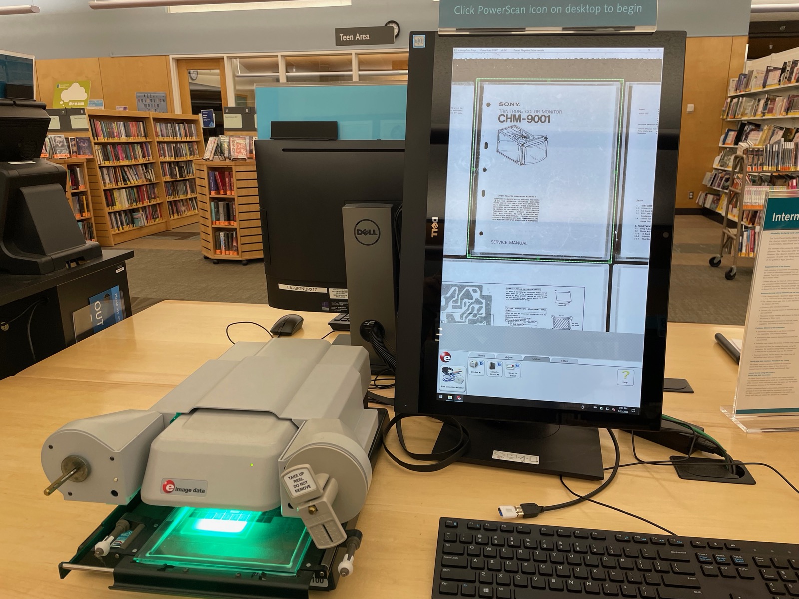
After a good hour of scanning all 37 pages, and quite a bit more than that processing all the images in Pixelmator, I now have the full service manual, with specifications, calibration routines, block diagram, schematic, and component list.
Sony CHM-9001-00 Details
Here’s the post-processed specification page of the service manual:
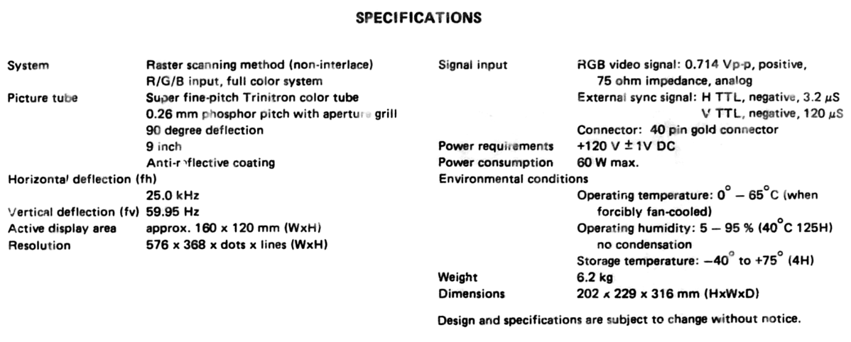
Of note here is the RGB video signal of 0.714 Vpp with 75 Ohm impedance. That matches the requirements of a VGA signal. We also see that both the H and V sync signals are negative polarity.
The schematic of the front-end circuit that interface with the outside world is also very helpful:
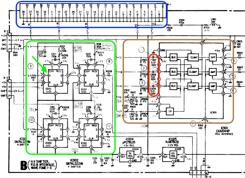
In blue, we can see that there are indeed only 5 pins on the display connector that are not connected to ground.
It’s not immediately obvious due to the way signals are merged into a bus, but the red region shows DC blocking series capacitors on the R, G, and B path. As theorized earlier, we don’t have to worry about the DC offset and should be able to directly connect a VGA signal to the CRT. Yay!
The brown region shows how the brightness and contrast inputs go to a blanking, clamping and amplification circuit for each of the 3 color components.
Finally, there’s the green region. It contains pulse generators that are triggered by the H-sync and the V-sync inputs. If you’re a bit familiar with video timings, you know that horizontal and vertical sync pulses are have either positive or negative polarity. However it was never completely clear to me why polarity was important.
In a modern monitor, the sync polarity, along with other timing parameters such as resolution, pixel clock etc, of an incoming video signal is sometimes matched against a list of official video timings to influence certain behaviors of a monitor. But sync polarity is never used to actually synchronize the video signal. In fact, most LCD panels with Vx1 or LVDS input interface don’t even require the sync signals. The blanking period is sufficient.
However, on old school fixed-timing displays such as this one, the sync signals are essential to control the CRT beam, and the correct polarity is important because there are discrete components that were configured specifically with a defined polarity in mind.
We can see that here with H-sync and V-sync: both signals immediately go to pin 9 of SN74LS221N, a negative edge trigger input of one of its two monostable multivibrators. That matches the requirements of a negative edge sync inputs.
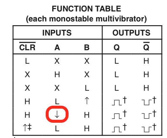
“Monostable multivibrator” is a complex way to saying “pulse extender”. Each 74LS221 has two such pulse extender, and if you look closely, you can also see 2 trim potentiometers, along with a capacitor above each pulse extender.
By having 2 pulse extenders connected both the H and V sync inputs, timing signals can be generated inside the CRT to tightly control when the CRT beam should be switched on or off both horizontally and vertically. For each direction, the first pulse extender controls where the beam should be enabled and the second one controls how long the beam should be enabled.
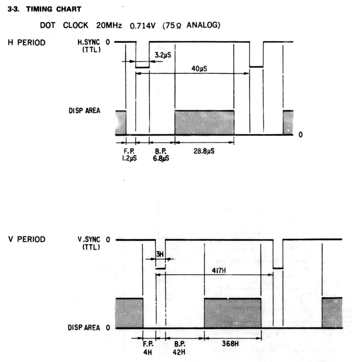
Another crucial piece of information in the service manual are the detailed video timings:
| Pixel clock | 20 MHz |
| Horizontal timings | |
|---|---|
| Period | 40uS |
| Frontporch | 1.2uS |
| Sync | 3.2uS |
| Backporch | 6.8uS |
| Active | 28.8uS |
| Vertical timings | |
| Period | 417 lines |
| Frontporch | 4 lines |
| Sync | 3 lines |
| Backporch | 42 lines |
| Active | 368 lines |
All modern monitors have square pixels. That’s not the case here: the stated active area of 160x120mm has an aspect ratio of 1.33 (4:3), but active resolution is specified at 576x368 or a ratio of 1.57.
Most video sources expect a sink with square pixels. It’d be incredibly annoying to not have square pixels on an LCD panel, because you’d either need a scaler to you’d need to insert black bars to the left and the right of the image. It’s less of an issue on a pure analog CRT, where individual pixels blend into each other horizontally anyway. You can lower the pixel clock from 20 MHz to 16.9MHz (=20*1.33/1.57), reduce the horizontal resolution from 576 to 485, and the analog-only circuitry of the CRT won’t have a clue that anything happened because all the timings would remain the same. The image quality might be a little bit lower because the CRT RGB raster won’t be the native resolution, chances are that nobody would notice.
One final detail, but an important one, are the power requirements: the CRT requires a 120V +-1V DC input. Where are you going to find a DC power supply like that???
Connecting the CRT to a VGA Port
I’ve spent quite a lot of words now on specifications details, let’s now put this information to work and use the CRT to display something that’s not the user interface of a logic analyzer.
In a first step, I wanted to focus only on the video interface itself while still using the the 120VDC power supply and the contrast and brightness controls of the original chassis.
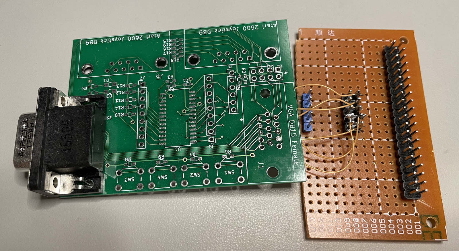
For the connection between a VGA source and the 40-pin cable I didn’t have to cut a precious VGA cable into pieces because I had still some a left over PCB and VGA connector from my VGA I2C joystick expander project.
Here’s my very rudimentary VGA to 40-pin connector adapter:
Next up was finding a suitable VGA source. In the future, I want to use a Pano Logic for that, but for this project I needed a source with fast configuration turnaround around time. None of my desktop PCs have a VGA output, but my trusty, old, and highly recommended X220 Thinkpad luckily still has one.
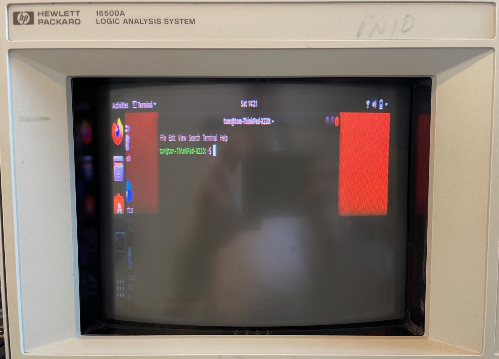
I didn’t take a picture of the X220 and the logic analyzer before I got things to work, so here’s the spoiler: the CRT of the logic analyzer showing an Ubuntu desktop:
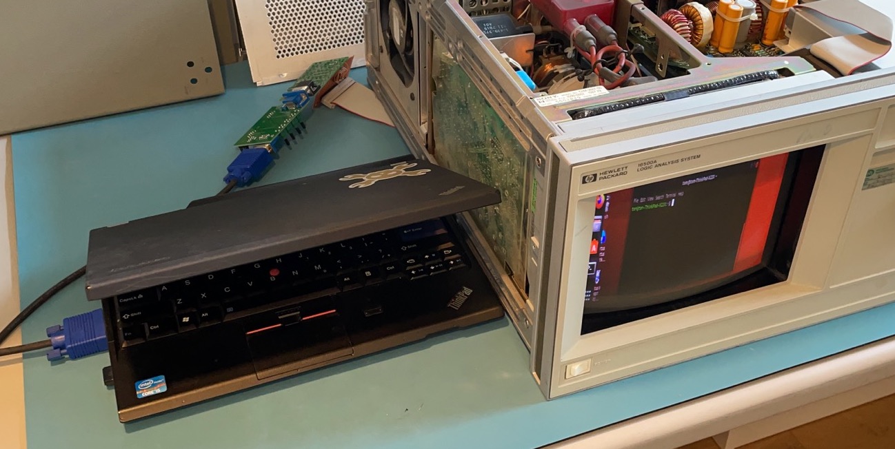
Getting to that point took much longer than it should have been.
If we want to stick with the native resolution, then we need to specify a 20MHz pixel clock, and the horizontal timings from the table above must be converted from microseconds to 20MHz clock cycles:
H period: 40uS        -> 800 cycles
H fp: 1.2uS           -> 24
H sync: 3.2uS         -> 64
H bp: 6.8uS           -> 136
H disp start: 10uS    -> 200
H disp time: 28.8uS   -> 576
The vertical timings are already in number-of-lines format and good to go…
Declare the video timings for a new 576x360@60Hz mode:
xrandr -d :0 --newmode "576x368_60" 20 \
    576 600 664 800 \
    368 372 375 417 \
    -VSync -HSync
Assign this new mode as a supported mode of the VGA port of the laptop:
xrandr -d :0 --addmode VGA-1 "576x368_60" --verbose
Switch the VGA port to this new mode:
xrandr -d :0 --output VGA-1 --mode "576x368_60" --verbose
This did not work!
Interestingly enough, however, it did result in the CRT lighting up with an image that was out of sync and with a resolution that was clearly higher than the desired 576x368?!
It took me a while to figure it out, but things became clear after looking at console log:
> dmesg
[  195.456360] [drm:ironlake_crtc_compute_clock [i915]]  ...
...  *ERROR* Couldn't find PLL settings for mode!
Here’s what was happening: the requested pixel clock of 20MHz was just too low: nobody at Intel expected that a 2012 laptop would ever need to drive 576x368 pixel display.
The solution to this was straightforward: double the pixel clock to 40MHz along with all the horizontal timing values. As I already explained above: the CRT unit is fully analog and only cares about absolute time values. Unlike modern protocols such as HDMI, it has no knowledge of a pixel clock. The vertical timings must stay the same.
The new mode is thus defined as follows:
xrandr -d :0 --newmode 1152x368_60 40 \
    1152 1200 1328 1600 \
    368 372 375 417 \
    -VSync -HSync
xrandr -d :0 --addmode VGA-1 "1152x368_60" --verbose
xrandr -d :0 --output VGA-1 --mode "1152x368_60" --verbose
The resulting image is squeezed due to the incorrect aspect ratio, but we have a stable image!
The ultimate goal is to use this CRT module as part of a retro-gaming setup. As a teaser, I downloaded a bitmap of a Pacman in the original resolution of 224x288:
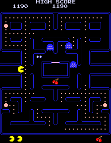
Rotate 90 degrees and point sample it to a to a 1152x368 bitmap:
convert pacman_native_90deg.png -sample 1152x368! pacman_native_90deg_sample.png
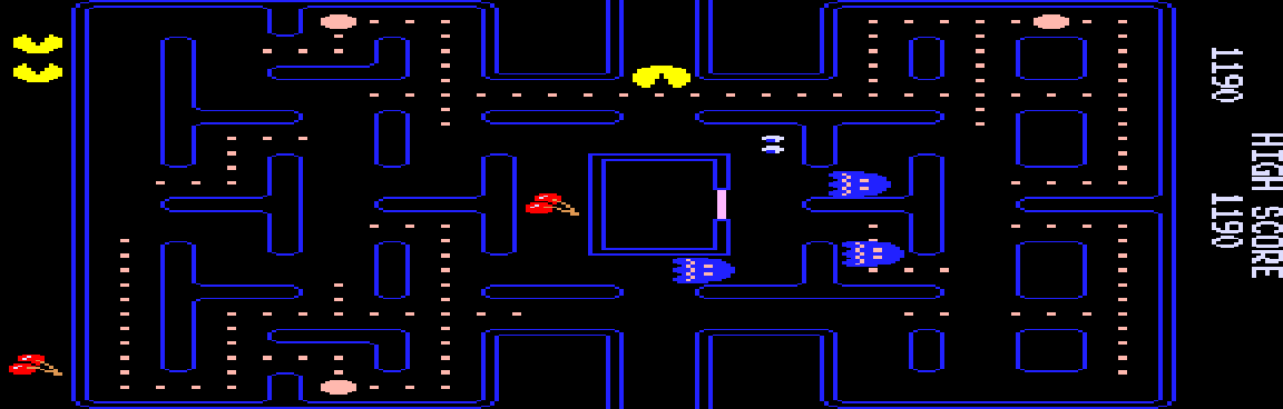
On the CRT:
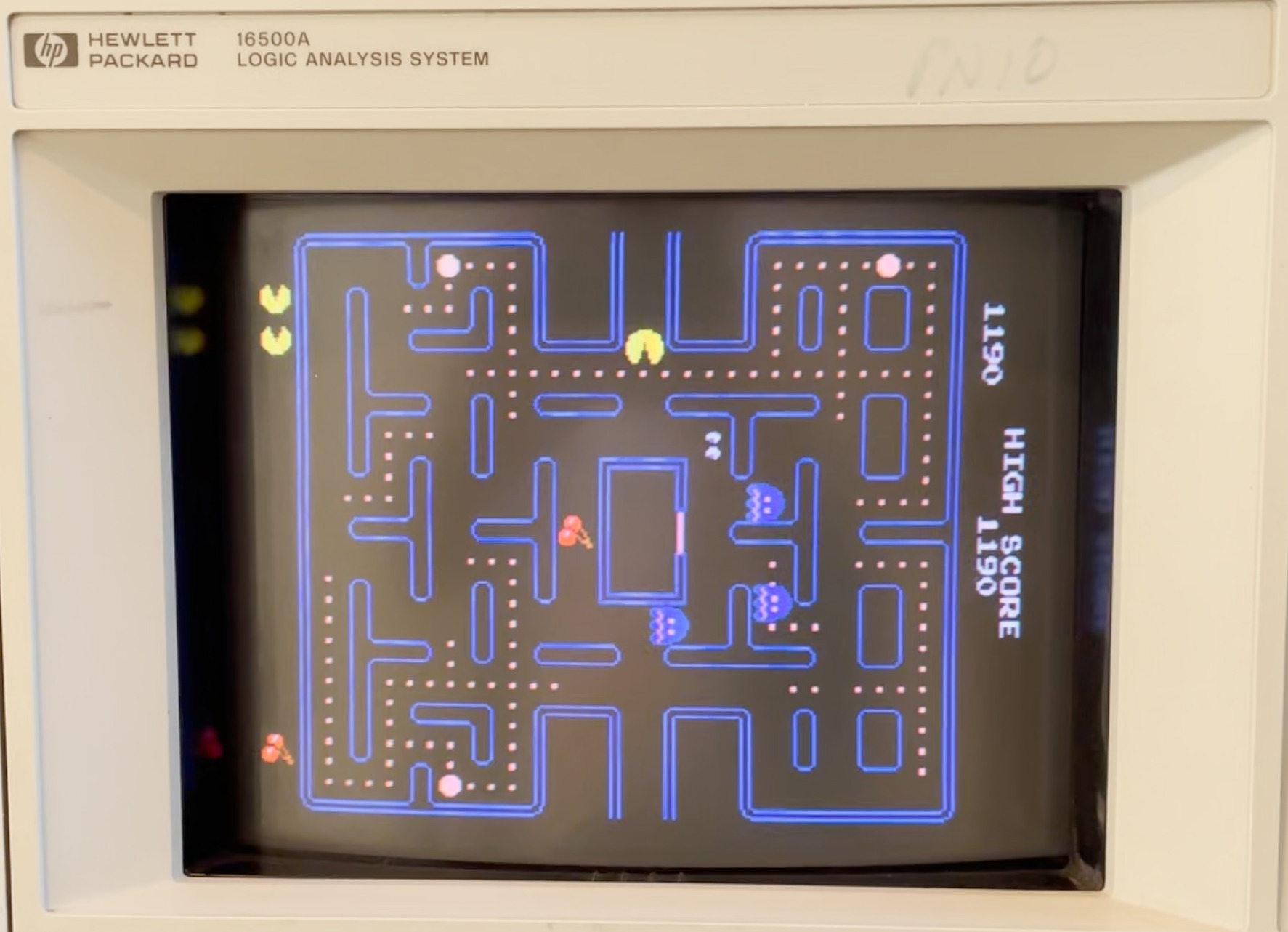
A real, working pacman will requires some scanout logic that does the conversion to 1152x368 in hardware, but that should be pretty easy to do.
Dropping the Logic Analyzer Chassis for a Stand Alone Power Supply
IMPORTANT: In this section I’m throwing together components that are not used for their intended purpose. There are no guarantees that the DC/DC convertor that I’m using here won’t blow up after extended use!!! And let’s once again not forget that I’m playing with 120VDC here. If you repeat my experiments, you do so at your own risk.
Using the logic analyzer chassis to generate the 120VDC power was a good temporary solution to bring up the CRT, but what if we want to use it stand-alone?
There are plenty of DC-DC converters out there to convert the output of, say, a 12VDC wall wart power supply into a stable 3V3, but 120VDC is just a different category. Eventually I found the following B900W DC-DC converter on AliExpress:
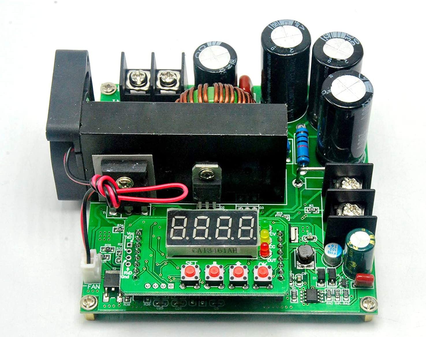
It’s supposed to be able to up-convert an input voltage between 8-60V up to 120V, for a maximum of 900W, way beyond the 60W that I need. And it’s a steal at $15. The B900W is supposed to be used to charge batteries from power sources such as solar cells or wind generators, but 120VDC is 120VDC, so why wouldn’t it work for my CRT?
I used my E3631A power supply to create 12V and configured the B900W to output 120VDC. It worked fine when unloaded, but when I wired up the output to the CRT power plug and switched on the power, then a second or so after hearing the characteristic sound of a CRT charging up, the B900W switched off. I tried multiple times, but always with the same result.
I thought that it was an issue with inrush current: a CRT has some very large coils that must be charged when powering up, so if you don’t do anything about it, you get this huge initial current surge. Rather than limiting the current to a maximum and gradually building up the voltage, the B900W simply trips a breaker and shuts down until the user resets it. This is probably the right behavior for a battery charger, but a power supply that shuts down it’s definitely not useful in this case.
I looked a little bit into common techniques to reduce inrush currents. The most common techniques seems to be the use of thermistors: at rest, they have a certain resistance, but when current flows through it, this resitance rapidly changes. You can have thermistors with positive or negative temperature coefficient (PTC or NTC). For my case, a NTC thermistor that’s placed in series with the 120VDC line might do the job: at rest, the resistance should be high enough to avoid tripping the over-current limit of the DC-DC convertor, and, if sized correctly, the current demands will be low enough once the thermistor has warmed up and the resistance has gone down.
I soldered together another dinky board together with a number of NTC thermistors in series, but that didn’t solve the problem: the B900W still shut down immediately after powering up.
Eventually, I realized that the B900W can support input voltages from 8 to 60V. Maybe converting from 12V to 120V was just too high of a ratio? I change my power supply to output 24V and… it worked!
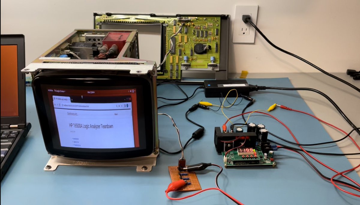
What you see in the picture above is:
- a 24V power brick. It’s the one that I use for my TS100 soldering iron.
- the 24V goes to the B900W that’s configured to output 119.9V, the maximum value.
- the 120V goes through the thermistor board. I’ve checked later that the setup still worked without the thermistors.
- the 120V goes to the CRT, which is displaying a browser window with my 16500A teardown blog post. :-)
In the back, you also see the front panel of the HP 16500A logic analyzer: I’m still using it to control contrast and brightness. Both are controlled by a 10K potentiometer. I didn’t have these laying around so I stuck with the original panel.
The technical requirements specify a 120VDC input that’s 1% accruate. I didn’t expect it, but it is indeed absolutely necessary to be this precise: reducing the voltage even by a little bit immediately shrinks the active image on the CRT.
I also noticed that the brightness of the image that’s sent by the X220 laptop is a bit on the low side. This is probably due to slightly different input voltages of the RGB signals, and something that should be correctable by playing with some trim potentiometers on the CRT.
Going Forward…
The work of getting the CRT up and running is pretty much complete, but as we say at work: demos are easy, making a product is hard. It’s a long term goal to build a portable retro-gaming setup base on this CRT and Pano Logic device.
For that, I’ll need to build a case, PCBs, give the power supply circuitry and disassembled Pano PCBs a place, and so forth.
It’s a project that will take a lot more effort than getting the electronics up and running on a lab bench, and something I’ll probably never finish. But who knows?