Pano Logic Update: VGA, VexRiscV CPU, Text Mode
- Introduction
- PCB Reverse Engineering Progress
- VGA Bringup
- Under the Hood: VexRiscV CPU
- Text Mode Output
- Conclusion
Introduction
One of my on-going projects is the reverse engineering of a Pano Logic Zero Client. Going forward, my Hackaday Project Page will mostly track the contents of this blog, but here are few earlier logs:
As usual, the gory technical details can be found on my Pano Logic GitHub repo.
I’ve made a lot of progress since I started working on it about a month ago.
PCB Reverse Engineering Progress
The most important resource are the connections between the FPGA and its surroundings. That information is captured in the top.ucf file.
Right now, the following interfaces have been mapped out:
-
IDT ICS307 clock generator
This interface is not only complete, but there is also RTL that successfully programs the generator into creating the pixel clock for 1080p VGA video timings. The RTL can be found here.
-
TI THS8135 10-BIT 240-MSPS VIDEO DAC
Nothing is more fun that having your own design generate and image and send it to a monitor, so this one had full priority. With this interface figured out, we can create the RGB signals. But that’s not enough! We also need:
-
Connector between board and daughter board
VGA doesn’t have HSYNC and VSYNC embedded in the RGB signals: it has separate pins for that. In order to create video, I had to figure out how the FPGA controls HSYNC and VSYNC.
In the process, a lot of other signals were also identified: USB signals, VGA DDC I2C pins, button, and LED control. No project is officially alive without a blinking LED.
-
Wolfson WM8750BL
Audio bringup soon!
-
DDR2 SDRAM
All pins identified.
-
NXT ISP1760 USB Host Controller
First pins identified.
VGA Bringup
With everything in place to create video signals, and some pretty simply RTL code, you can now see the following:
Pano Logic 1080p VGA Output from Tom Verbeure on Vimeo.
Under the Hood: VexRiscV CPU
With video figured out, it’s time to move to bring up other interfaces. Audio is quite simple, so that’s high on the list.
But we really need a CPU to make that kind of bringup easy. For example, the Wolfson CODEC is configured through I2C. I’m already using a bit-banged I2C master on a Nios2 for my eeColor Color3 project. I want to do the same here.
That’s why the project now also has a VexRiscV!
A seperate post will go into the details about the specifics of this RISC-V core, but the most important reasons to choose this one over the ubiquitous PicoRV32 are:
-
Xilinx ISE 14.7 and PicoRV32 aren’t friendly.
It’s totally possible to make it work with relatively minor RTL edits, but that was only true when you don’t use using the HW multiplier. Using the multiplier breaks the terrible Xilinx software. Meanwhile, ISE was able to grok the VexRiscV on first try, multiplier and all.
-
The VexRiscV is much faster.
Or better, the PicoRV32 is really slow, coming in at 3 to 7 cycles per instruction. The VexRiscV is just as configurable as the PicoRV32 and can go at one cycle per instruction without trying very hard. (It’s currently running at 2 cycles per instruction though.)
It’s not that we need a faster CPU for our current purposes, but the amount of logic resources for the VexRiscV is almost the same as for the PicoRV32. And it’s fun to explore different cores. So why not?
At this time, the CPU is only used to blink the LEDs (yay!). That’s because some other infrastructure is necessary to really start using it: a way to tell the user what’s going on. That’s why the following was developed:
Text Mode Output
And as of today, there is also a character generator:
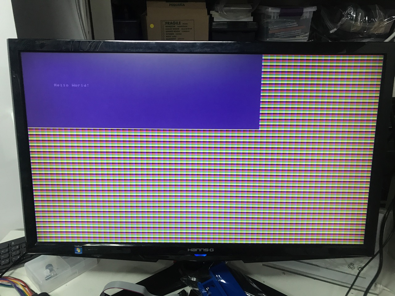
The GitHub repo is always in a state of flux, but that example can be generated by syncing to this commit.
The screen buffer hasn’t been connected to the CPU yet, but once that’s done, everything will be in place to start driving other parts of the PCB.
(Sadly, the Commodore 64 font will be replaced by the vintage IBM 8x12 character set, since the latter is ASCII mapped out of the box.)
Conclusion
Lots of progress. More to come!
Next step: getting audio-out to work.