HP/Agilent E3631A Rotary Knob Repair
Probably too many pictures and too much text for what’s in the end a pretty straightforward 45min repair…
Introduction
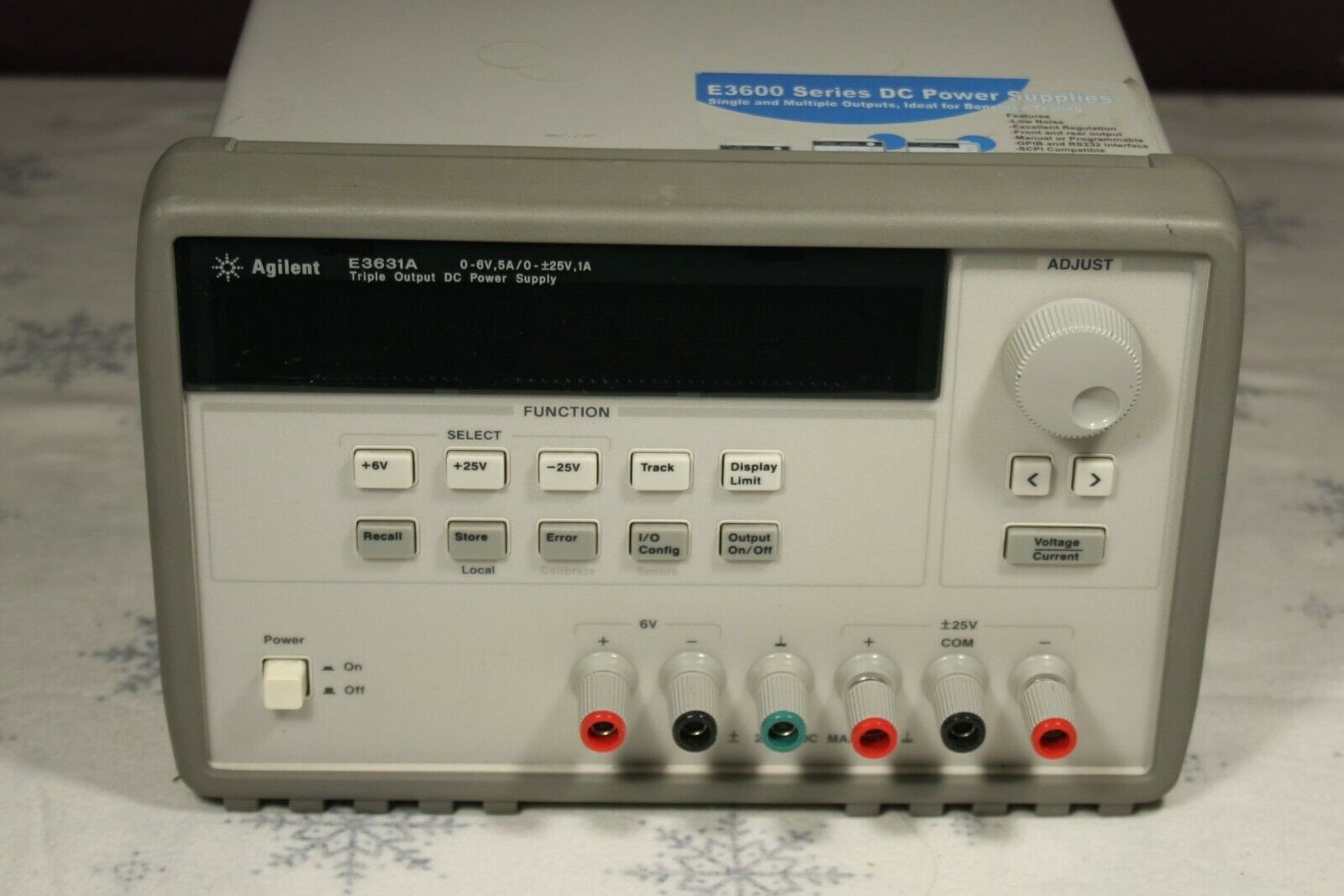
A few weeks ago, somebody on Twitter proudly posted a picture of his ‘new’ Agilent E3631A power supply. I had been looking on and off for a quality power supply for a while, but never gotten around to investigating which one to buy. That tweet made me look a some more, and the E3631A seemed to be an excellent choice, even if a bit overqualified for my needs:
- 3 independent voltage rails: 0 to 6V (5A max), 0 to 25V (1A max), and 0 to -25V (1A max)
- all kinds of cool high precision, low noise and low ripple specifications
- GPIB and RS232 control
-
“small, compact size for bench use”, according to the marketing department
Don’t believe this: the thing is built like a tank and at 18lbs weighs the part. It makes quite a bit of noise too.
On eBay, the going rate for a working one is ~$430 + tax but I found one on offer on Craigslist for $300.
The seller only wanted to meet on the parking lot of a 7/11 in Milpitas, with no way to check the goods. He promised a 7-day return period but who knows how that will turn out in practice?
Still, for the price I decided to go for it. If all goes well, this might be the last bench power supply I’ll buy.
Rotary Knob Problem
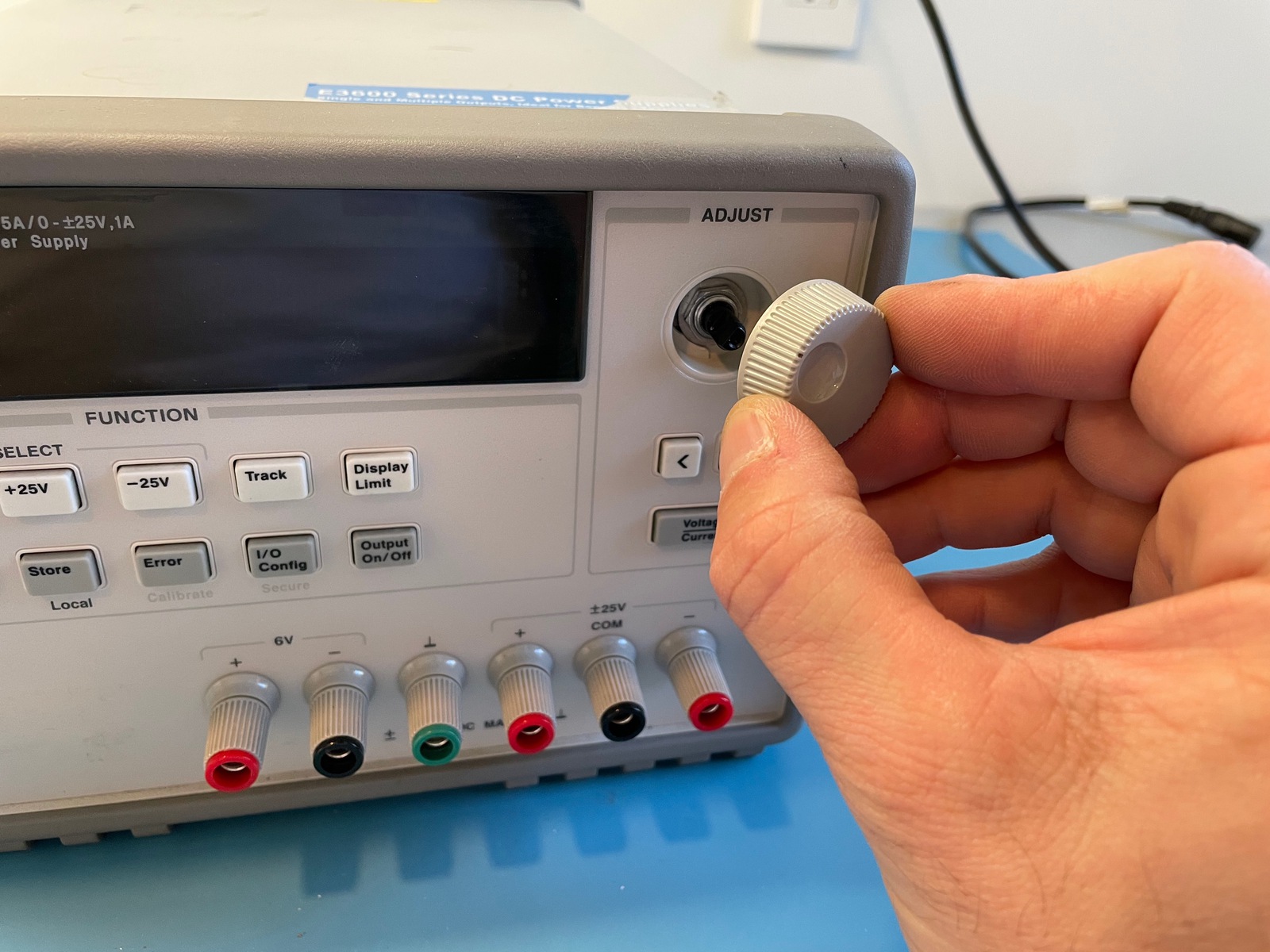
The power supply came up just fine. Display worked, buttons worked, there was a voltage on the power connectors, but the rotary knob worked … only a little bit. It wasn’t totally broken, but you had to finesse it by rotating very slowely to make it respond.
Turns out that this is a common issue with HP/Agilent equipment in general. It’s also something that’s easy to fix. After the upgrade adventures with my TDS 420A, I felt confident enough to do this myself, rather than trying to get my money back on what was still a good deal.
Replacing the Knob
Traditional disclaimers:
Make sure that you disconnect the power cord before attempting a repair like this!!! Don’t do this if you’re not comfortable with the thought of getting a 110V shock!!! If your PSU is still under warranty, expect it to be void after doing stuff like this!
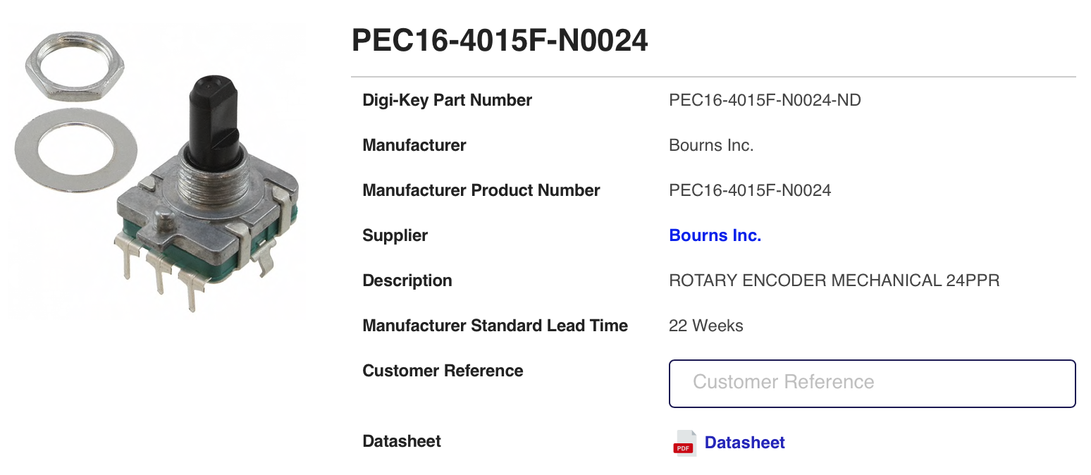
There are 2 types of rotary encoders: smooth rotating ones (“no detent”) and ones where you can feel a click when you turn it (“detent”). Some people prefer the latter, but I decided on the smooth one to keep it the same as the original.
I bought this rotary encoder on DigiKey for $1.20 and paid triple that for shipping.
Remove the knob
Just pull a bit, it should come off easily.
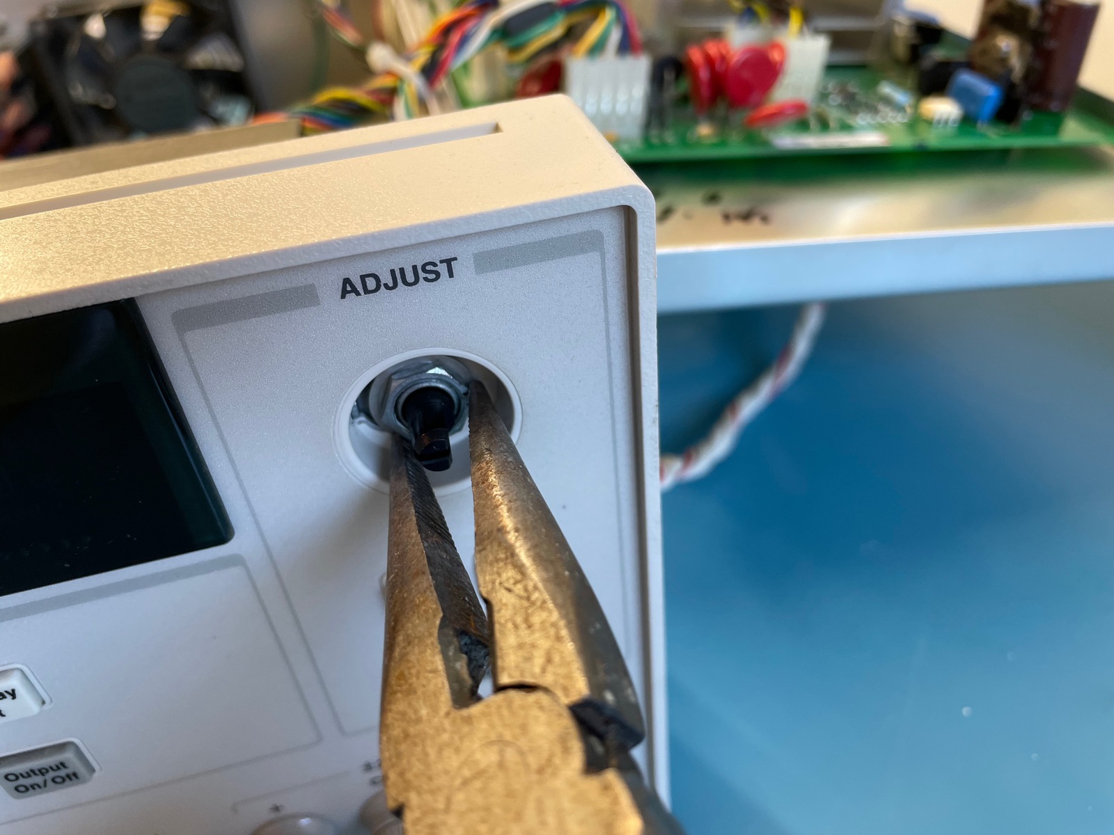
Remove the rotary encoder nut and washer
Fast Forward to “Lift PCB retaining tab and slide out PCB”
Kevin reported that it’s possible to replace the rotary knobs by just removing the front panel, without the need to completely dismantle the rest of the unit:
After opening my first unit and making a repair, I realized that Agilent left enough slack in the front panel cable bundle such that you can make this repair without opening up the back frame, outer sleeve, and cage. To do this, do everything until “Remove back frame”. Then, remove the front panel screws and gently pull the front panel out. Of course, the cable will still be attached, but you can fold it down far enough to lift the retaining tab and unplug the front cable bundle to detach the front panel PCB.
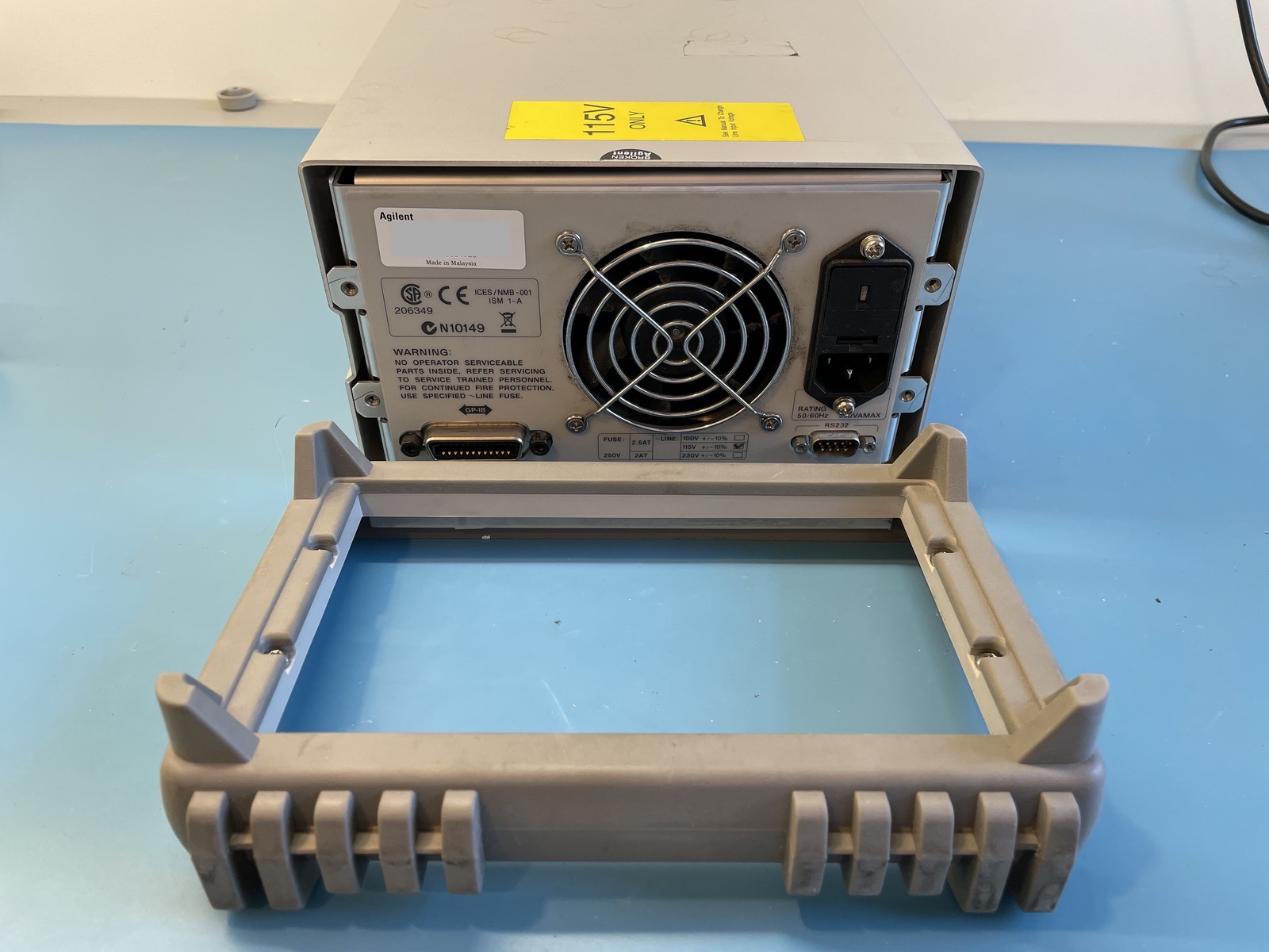
Remove back frame
If the power supply warranty sticker wasn’t broken yet, removing the back frame wil do so!
Rather than first removing the protection rubber and then the frame, it’s easier to remove the 4 screws and take off the combination of the rubber and the plastic frame as one piece.
Remove handle and side screws
These 4 screws fix the inner power supply cage connected to the outer metal sleeve.
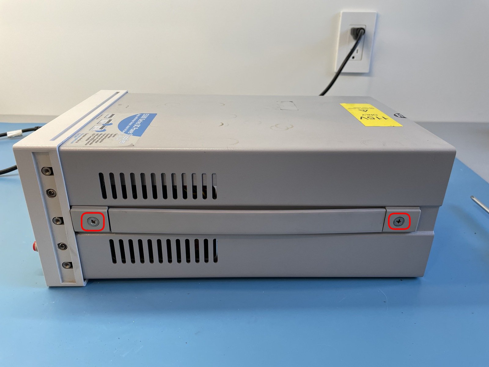
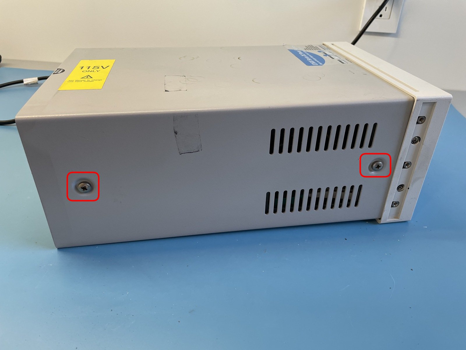
Some E3631A versions only have the 2 screws of the handle to hold the chassis in place.
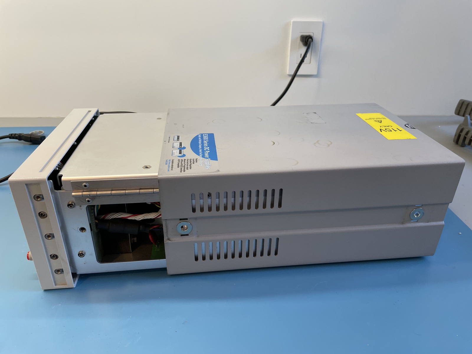
Slide off the outer sleeve
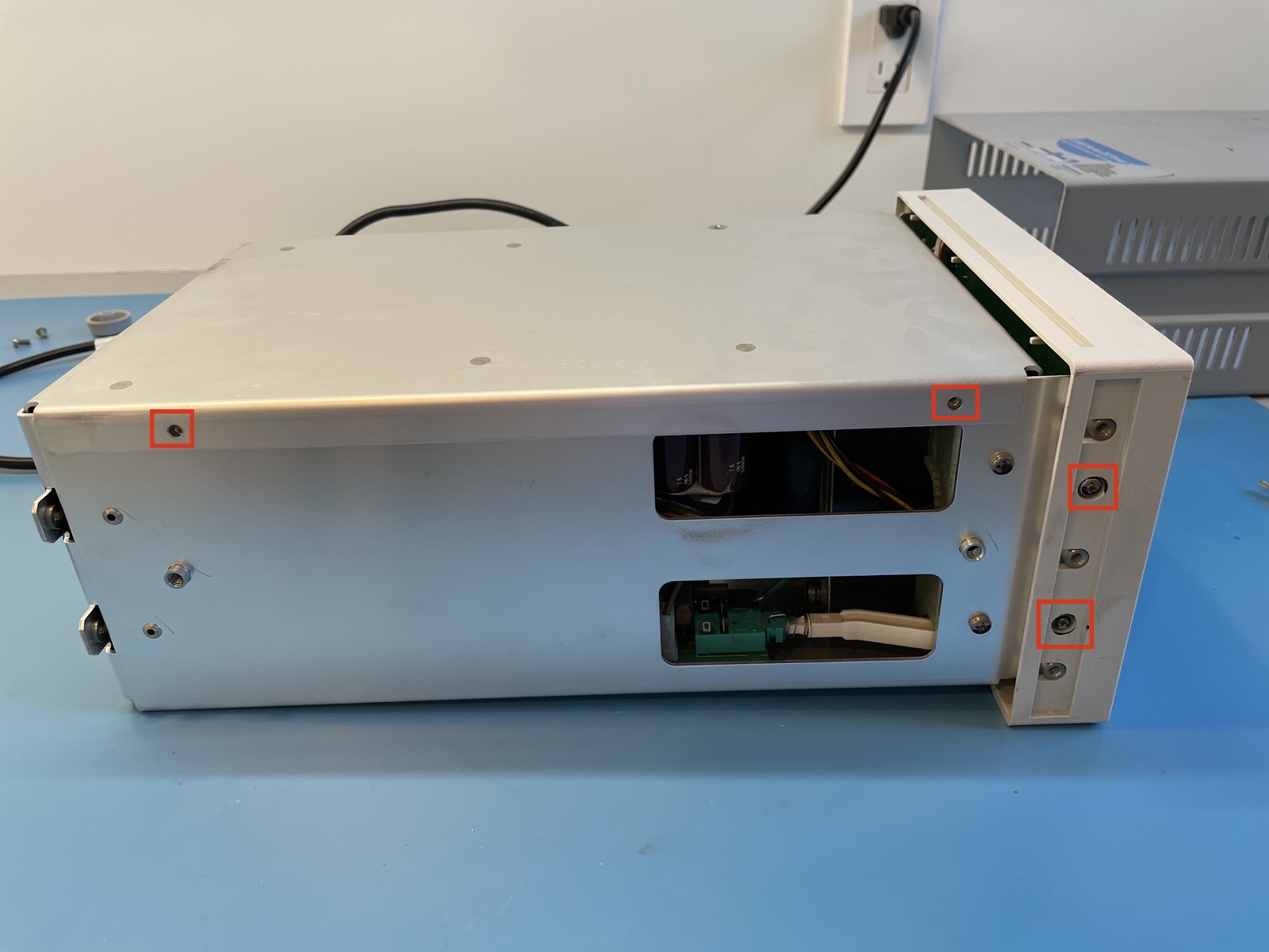
Remove cage lock and front panel screws
The power supply is built into a fold-open cage. 2 screws lock the top of the cage in place.
There are also 2 screws on each side that fix the front panel to the cage.
When the screws are removed, don’t try to pull away the front panel too far: there’s a cable that connects the front panel to an inner PCB.
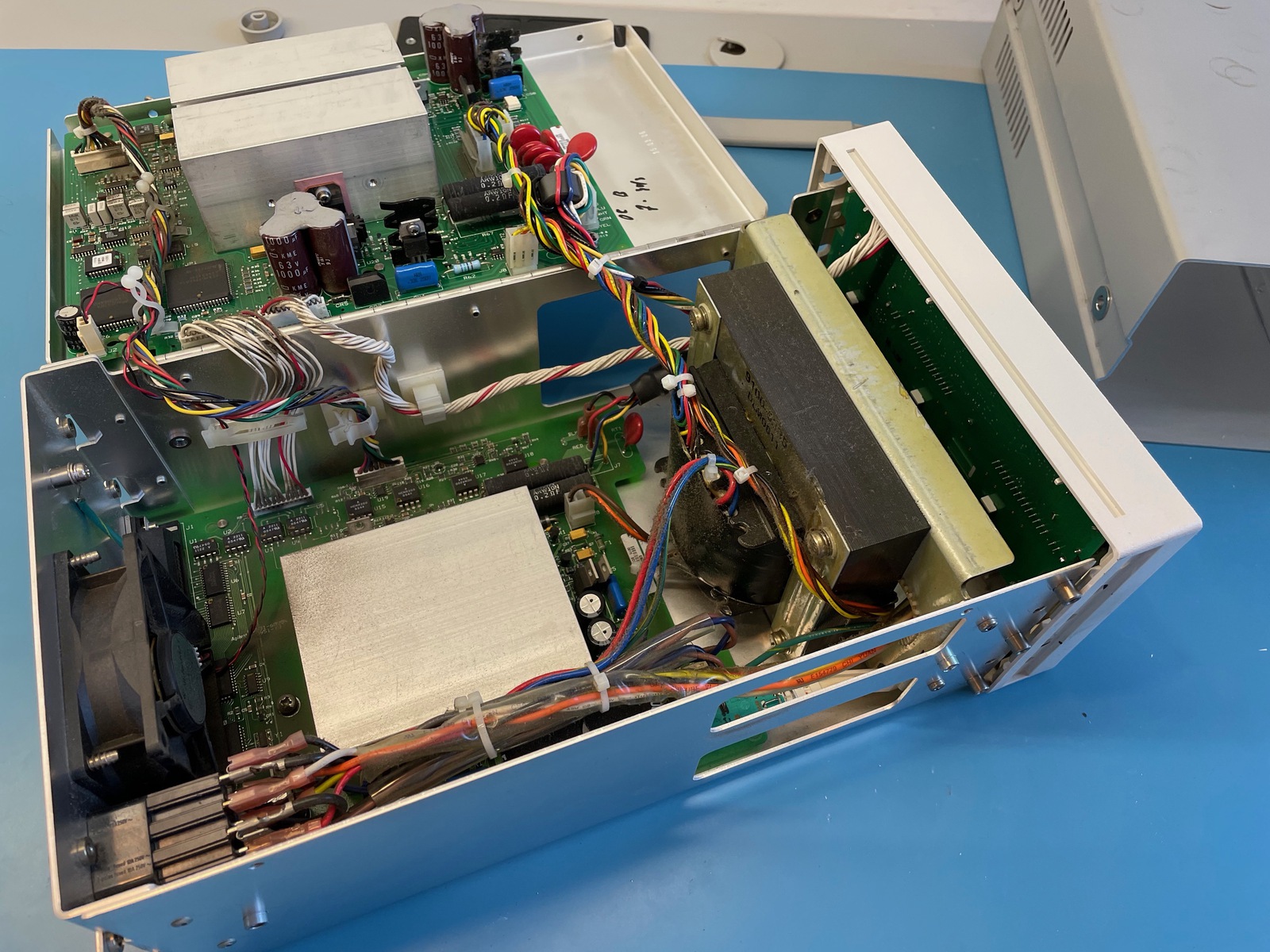
Open the cage
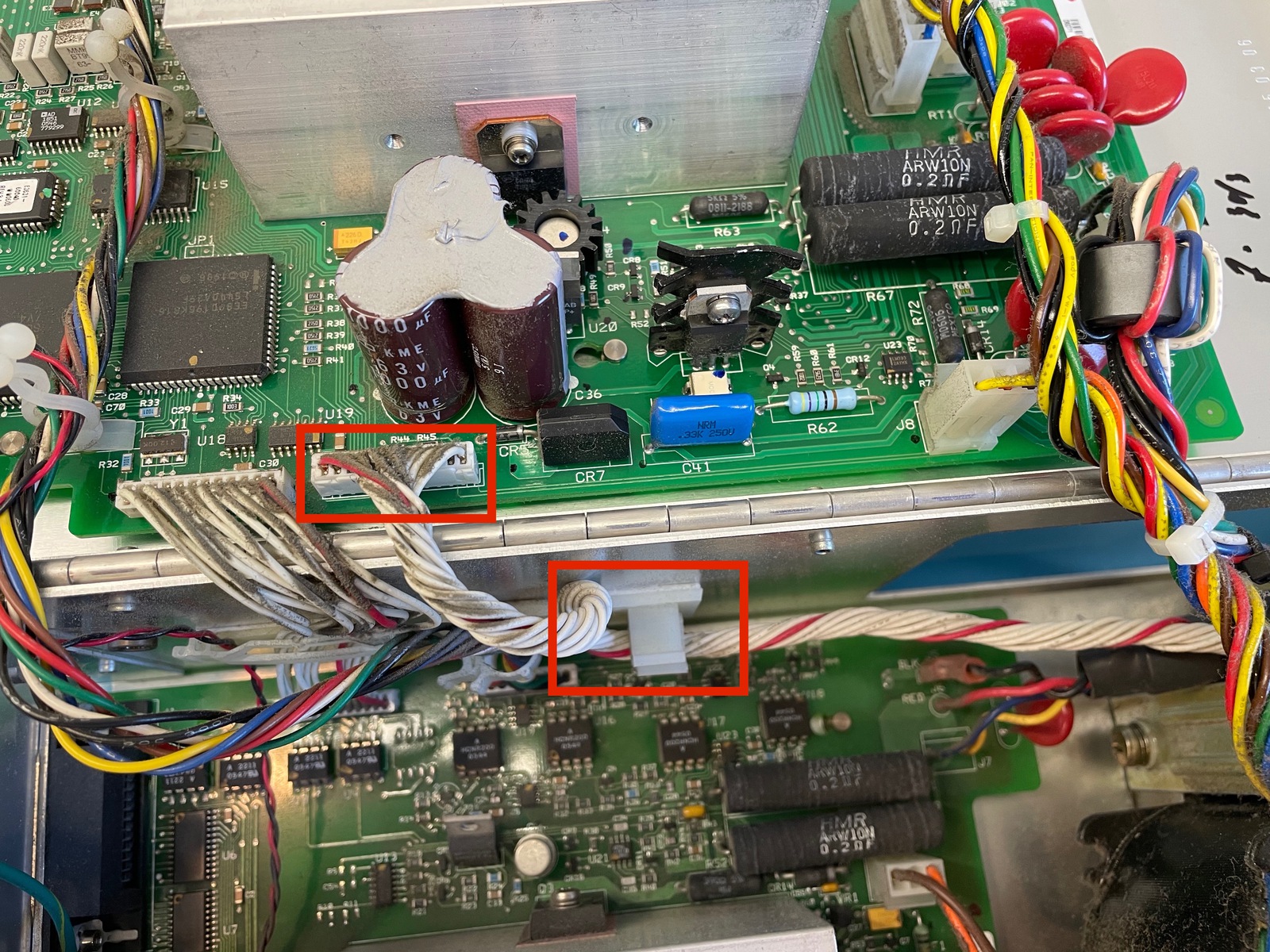
Unplug the front panel cable
You’ll need to wiggle with quite a bit to unplug the connector from its socket. Also remove the cable from the plastic locking retainer. The cable needs to be completely loose.
Pull the cable out of the hole that’s next to the transformer as well.
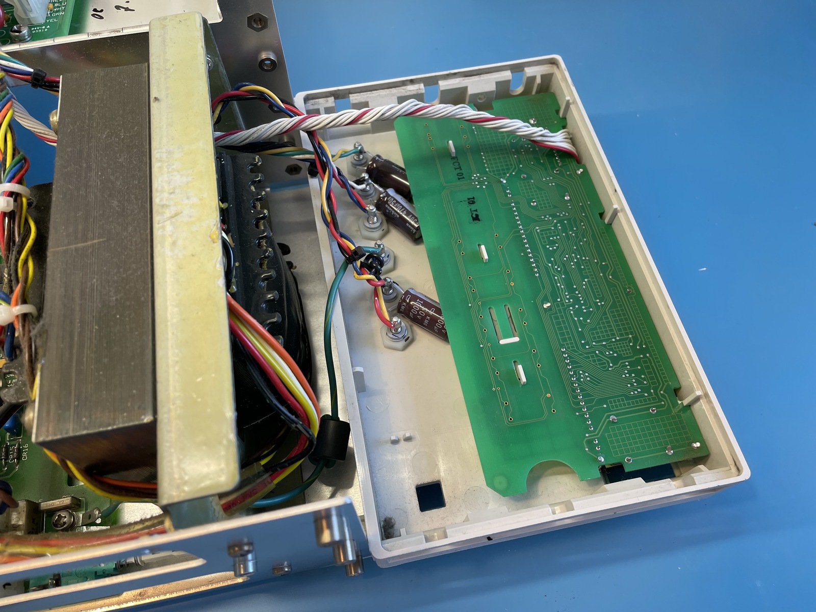
Fold open the front panel
With the cable loose, you can now fold open the front panel. It will still be connected to the main PCB with some other wires, but it’s sufficient to remove the front panel PCB.
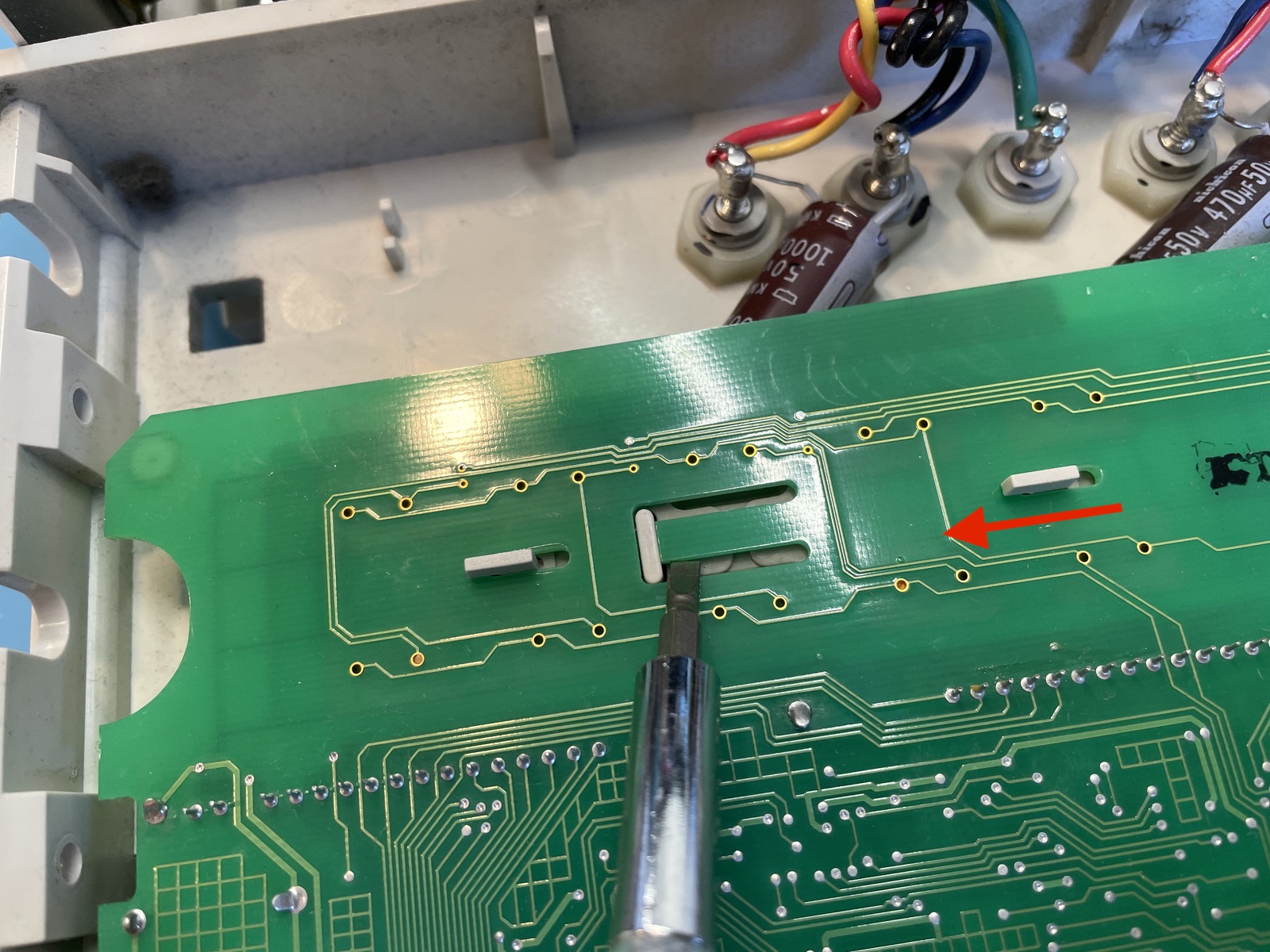
Lift PCB retaining tab and slide out PCB
The front panel PCB is fixed to the front panel with a slide-and-click mechanism.
Removing it is very easy (as long as you didn’t forget the rotary knob nut at the start!) Just gently lift the retaining tab with a screwdrive and slide the PCB off the front panel.
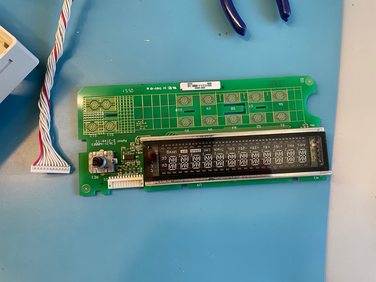
Remove cable from panel PCB
The cable will be in the way when doing your soldering work, so just unplug that one too.
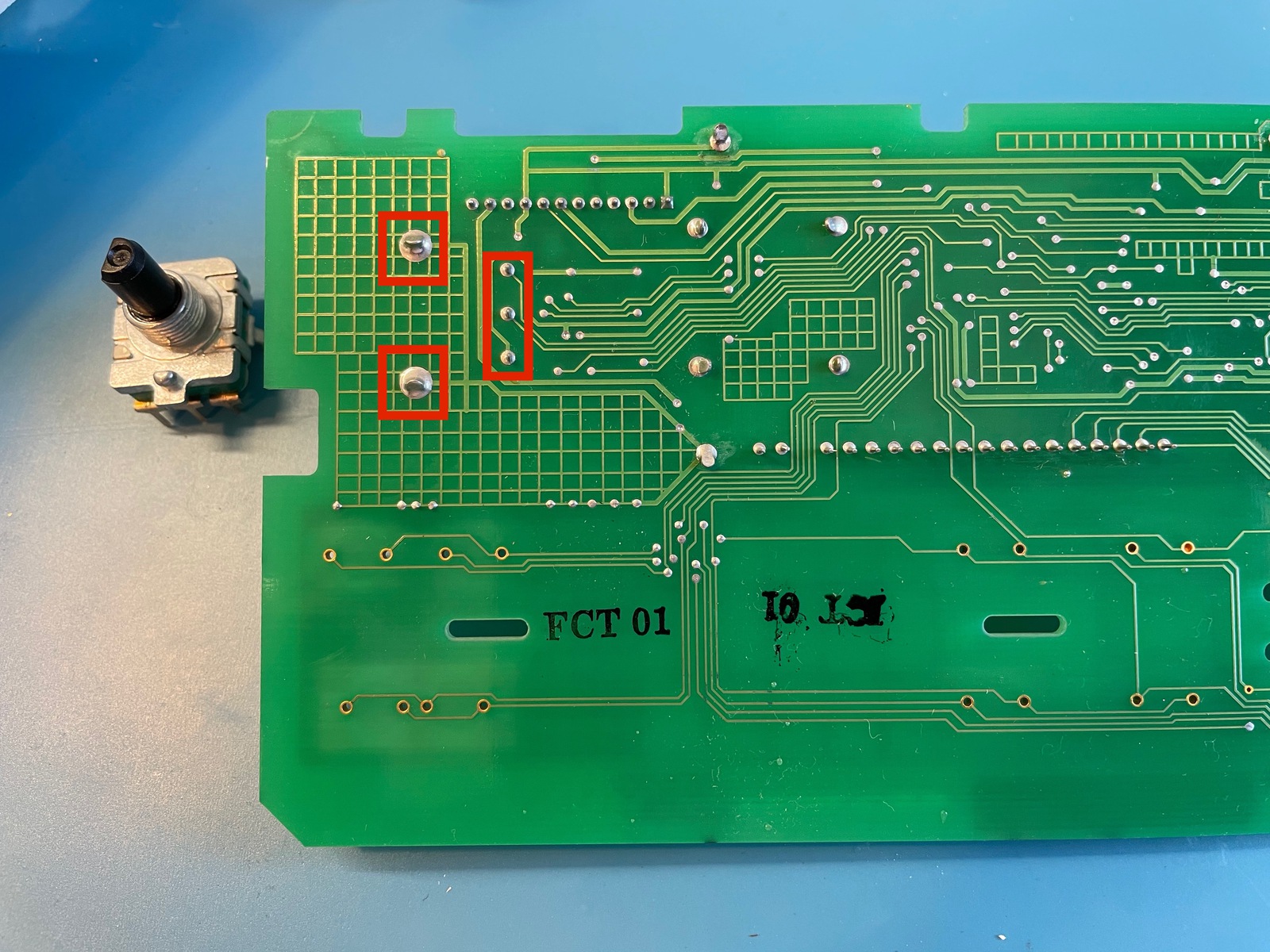
Replace the rotary encoder
All that’s left now is replacing the old rotary knob. This was easier that I thought it would be. With a hot iron (I probably overdid it at 400C!) and some soldering wick, it took less than 10min to remove the solder of the 5 connection points. The old knob came off very cleanly.
Adding the new encoder was obviously even easier.
You’ll just have to believe that this is a photo with the old encoder replaced by the new one…
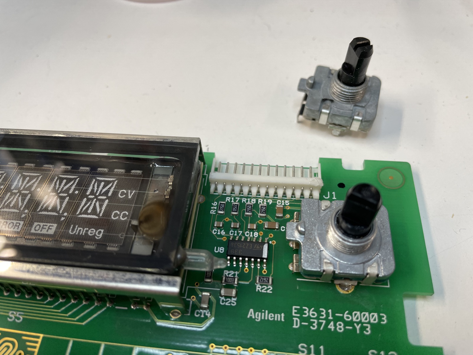
Check that it’s working…
I did a quick check that things worked, before closing things up in reverse order…
Success!!!
Time spent from start to finish: 45 min.
References
- Blog post about my second E3631a: The Agilent/HP E3631A Power Supply Repair that Wasn’t