Making Screenshots of Test Equipment Old and New
- Introduction
- Screenshot Capturing Interfaces
- Hardware and Software Tools
- Capturing GPIB data in Talk Only mode
- TDS 540 Oscilloscope - GPIB - PCL Output
- HP 54542A Oscilloscope - Parallel Port - PCL or HPGL Output
- HP Inifinium 54825A Oscilloscope - Parallel Port - Encapsulated Postscript
- TDS 684B - Parallel Port - PCX Color Output
- Advantest R3273 Spectrum Analyzer - Parallel Port - PCL Output
- HP 8753C Vector Network Analyzer - GPIB - HP 8753 Companion
- Siglent SDS 2304X Oscilloscope - USB Drive, Ethernet or USB
- Footnotes
Introduction
Last year, I created Fake Parallel Printer, a tool to capture the output of the parallel printer port of old-ish test equipment so that it can be converted into screenshots for blog posts etc.
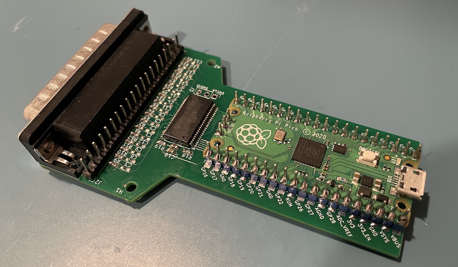
It’s definitely a niche tool, but of all the projects that I’ve done, it’s definitely the one that has seen the most amount of use.
One issue is that converting the captured raw printing data to a bitmap requires recipes that may need quite a bit of tuning. Some equipment uses HP PCL, other Encapsulated Postscript (EPS), if you’re lucky the output is a standard bitmap format like PCX.
In this blog post, I describe the procedures to create screenshots of test equipment that I personally own so that I don’t need to figure it out again when I use the device a year later. That doesn’t make it all that useful for others, but somebody may benefit from it when googling for it… As always, I’m using an Ubuntu Linux distribution so the software used below reflects that.
Screenshot Capturing Interfaces
Here are some common ways to transfer screenshots from test equipment to your PC:
-
USB flash drive
Usually the least painless by far, but it only works on modern equipment.
-
USB cable
Requires some effort to set the right
udevdriver permissions and a script that sends commands that are device specific. But it generally works fine. -
Ethernet
Still requires slightly modern equipment, and there’s often some configuration pain involved.
-
RS-232 serial
Reliable but slow.
-
Floppy disk
I have a bunch of test equipment with a floppy drive and I also have a USB floppy drive for my PC. However, the drives on all this equipment is broken, in the sense that it can’t correctly write data to disk. There must be some kind of contamination going on when the floppy drive head hasn’t been used for decades.
-
GPIB
Requires an expensive interface dongle1 and I’ve yet to figure out how to make it work for all equipment. Below, I was able to make it work for a TDS 540 oscilloscope, but not for an HP 54532A oscilloscope, for example.
-
Parallel printer port
Available on a lot of old equipment, but it normally can’t be captured by a PC unless you use Fake Parallel Printer. I use it all the time: it’s often easiest to set up of all the printer interfaces.
Hardware and Software Tools
GPIB to USB Dongle
If you want to print to GPIB, you’ll need a PC to GPIB interface. These days, the cheapest and most common are GPIB to USB dongles. I’ve written about those here and here.
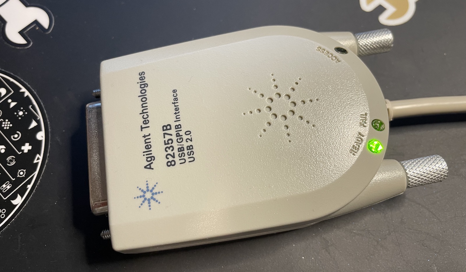
Even if you can find a cheap one, the biggest issue is that they are hard to configure when using Linux. And as mentioned above, I have only had limited success at using them in printer mode.
ImageMagick
ImageMagick is the swiss army knife of bitmap file processing. It has a million features, but I primarily use it for file format conversion and image cropping.
I doubt that there’s a major Linux distribution that doesn’t have it as a standard package.
sudo apt install imagemagick
GhostPCL
GhostPCL is used to decode PCL files. On many old machines, these files are created when printing to Thinkjet, Deskjet or Laserjet.
Installation:
- Download the GhostPCL/GhostPDL source code.
- Compile
cd ~/tools
tar xfv ~/Downloads/ghostpdl-10.03.0.tar.gz
cd ghostpdl-10.03.0/
./configure --prefix=/opt/ghostpdl
make -j$(nproc)
export PATH="/opt/ghostpdl/bin:$PATH"
- Install
sudo make install
A whole bunch of tools will now be available in /opt/ghostpdl/bin, including
gs (Ghostscript) and gpcl6.
hp2xx
hp2xx converts HPGL files, originally intended for HP plotters, to bitmaps, EPS etc.
It’s available as a standard package for Ubuntu:
sudo apt install hp2xx
Inkscape
Inkscape is full-featured vector drawing app, but it can also be used as a command line tool to convert vector content to bitmaps. I use it to convert Encapsulated Postscript file (EPS) to bitmaps.
Like other well known tools, installation on Ubuntu is simple:
sudo apt install inkscape
HP 8753C Companion
This tool is specific to HP 8753 vector network analyzers. It captures HPGL plotter commands, extracts the data, recreates what’s displayed on the screen, and allows you to interact with it.
It’s available on GitHub.
Capturing GPIB data in Talk Only mode
Some devices will only print to GPIB in Talk Only mode, or sometimes it’s just easier to use that way.
When the device is in Talk Only mode, the PC GPIB controller becomes a Listen Only device, a passive observer that doesn’t initiate commands but just receives data.
I wrote the following script to record the printing data and save it to a file:
gpib_talk_to_file.py:
(Click to download)
#! /usr/bin/env python3

import sys
import pyvisa

gpib_addr       = int(sys.argv[1])
output_filename = sys.argv[2]

rm = pyvisa.ResourceManager()

inst = rm.open_resource(f'GPIB::{gpib_addr}')

try:
    # Read data from the device
    data = inst.read_raw()

    with open(output_filename, 'wb') as file:
        file.write(data)

except pyvisa.VisaIOError as e:
    print(f"Error: {e}")
Pyvisa is a universal library to talk to test equipement. I wrote about it here. When in Talk Only mode, the script will quickly time out when no data arrives, but since all data transfers happen with a valid-ready protocol, you can avoid time-out issues by pressing the hardcopy or print button on your oscilloscope first and only then launch the script above.
This will work as long as the printing device doesn’t go silent while in the middle of printing a page in which case a time out could still happen.
TDS 540 Oscilloscope - GPIB - PCL Output
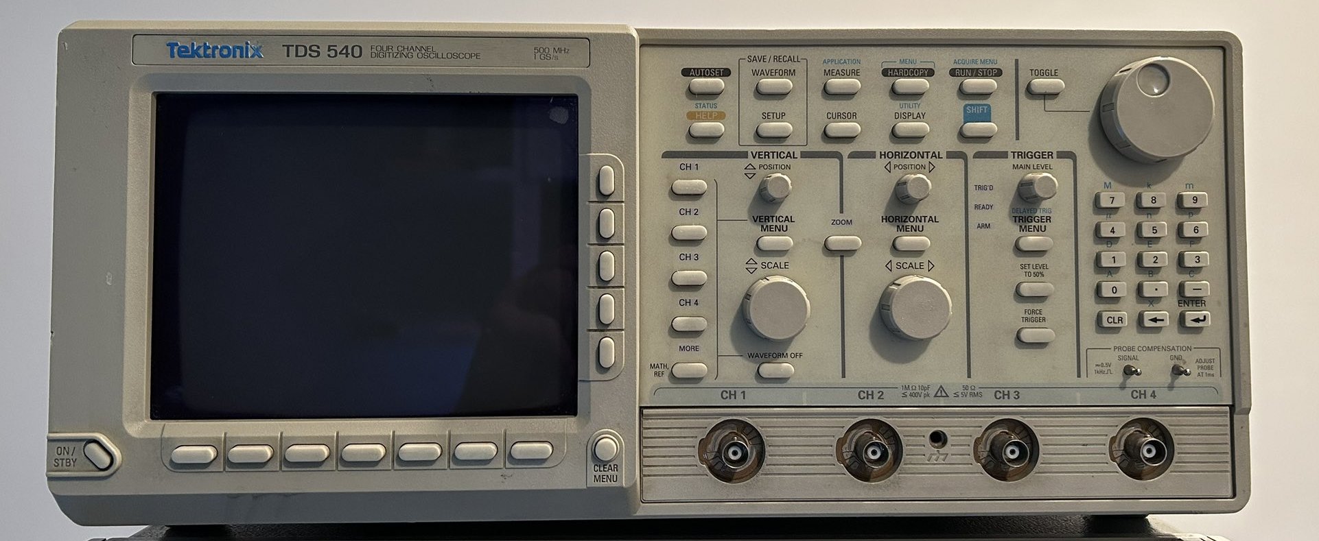
My old TDS 540 oscilloscope doesn’t have a printer port, so I had to make do with GPIB. Unlike later versions of the TDS series, it doesn’t have the ability to export bitmaps directly but it has outputs for:
- Thinkjet, Deskjet, and Laserjet in PCL format
- Epson in ESC/P format
- Interleaf format
- EPS Image format
- HPGL plotter format
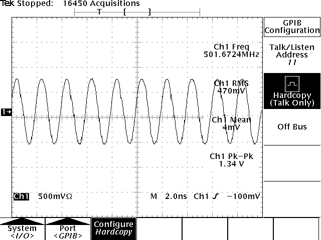
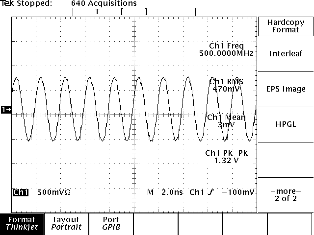
The TDS 540 has a screen resolution of 640x480. I found the Thinkjet output format, with a DPI of 75x75, easiest to deal with. The device adds a margin of 20 pixels to the left, and 47 pixels at the top, but those can be removed with ImageMagick.
With a GPIB address of 11, the overall recipe looks like this:
# Capture the PCL data
gpib_talk_to_file.py 11 tds540.thinkjet.pcl
# Convert PCL to png
gpcl6 -dNOPAUSE -sOutputFile=tds540.png -sDEVICE=png256 -g680x574 -r75x75 tds540.thinkjet.pcl
# Remove the margins and crop the image to 640x480
convert tds540.png -crop 640x480+20+47 tds540.crop.png
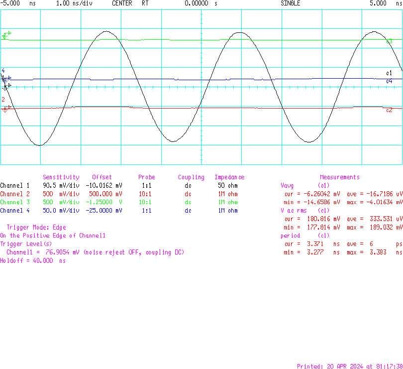
The end result looks like this:
HP 54542A Oscilloscope - Parallel Port - PCL or HPGL Output
This oscilloscope was a ridiculous $20 bargain at the Silicon Valley Electronics Flea Market and it’s the one I love working with the most: the user interface is just so smooth and intuitive. Like all other old oscilloscopes, the biggest thing going against it is the amount of desk space it requires.
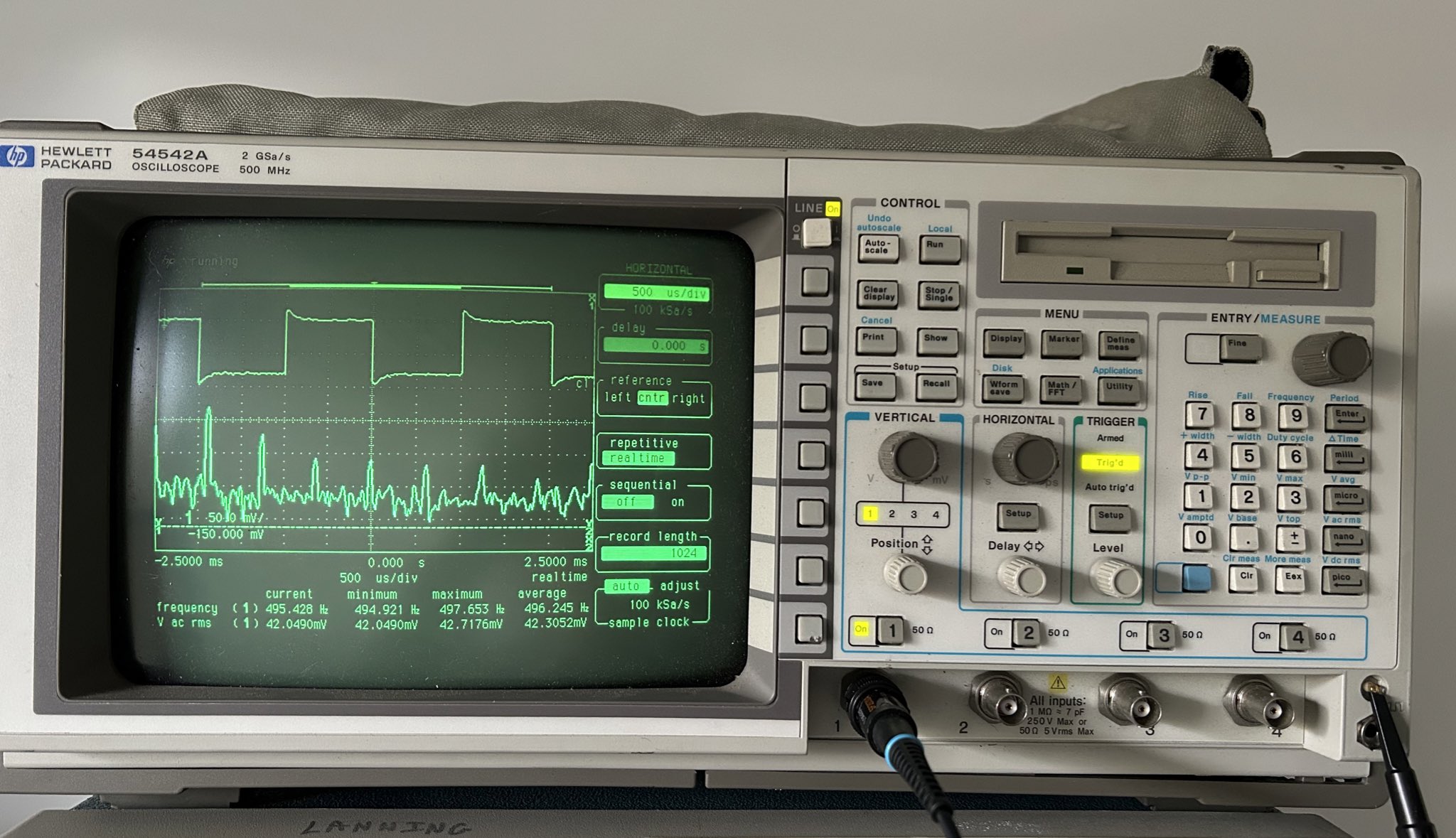
It has a GPIB, RS-232, and Centronics parallel port, and all 3 can be used for printing.
I tried to get printing to GPIB to work but wasn’t successful: I’m able to talk to the device and send commands like “*IDN?” and get a reply just fine, but the GPIB script that works fine with the TDS 540 always times out eventually.
I switched to my always reliable Fake Parallel Printer and that worked fine. There’s also the option to use the serial cable.
The printer settings menu can by accessed by pressing the Utility button and then the top soft-button with the name “HPIB/RS232/CENT CENTRONICS”.
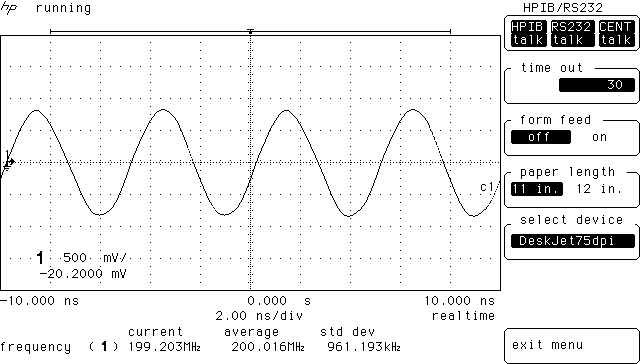
You have the following options:
- ThinkJet
- DeskJet75dpi, DeskJet100dpi, DeskJet150dpi, DeskJet300dpi
- LaserJet
- PaintJet
- Plotter
The supported formats are definitely HP centric! Unlike the TDS 540 I wasn’t able to get the ThinkJet option to convert into anything, but the DeskJet75dpi option worked fine with this recipe:
~/projects/fake_parallel_printer/fake_printer.py -i -p /dev/ttyACM0 -f hp54542a_ -s deskjet.pcl -v
gpcl6 -dNOPAUSE -sOutputFile=hp54542a.png -sDEVICE=png256 -g680x700 -r75x75 hp54542a_0.deskjet.pcl
convert hp54542a.png -crop 640x388+19+96 hp54542a.crop.png
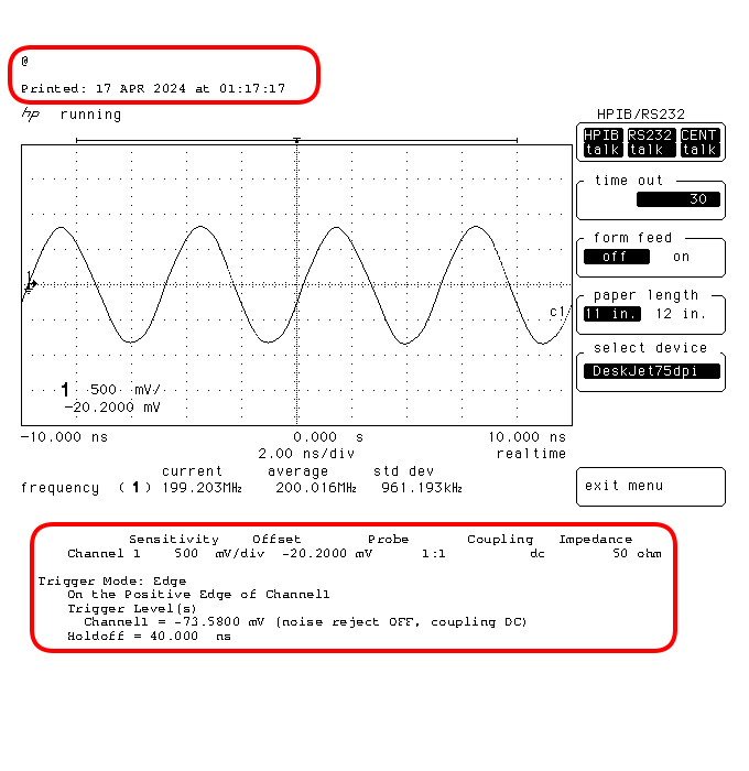
The 54542A doesn’t just print out the contents of the screen, it also prints the date and adds the settings for the channels that are enabled, trigger options etc. The size of these additional values depends on how many channels and other parameters are enabled.
When you select PaintJet or Plotter as output device, you have the option to select different colors for regular channels, math channels, graticule, markers etc. So it is possible to create nice color screenshots from this scope, even if the CRT is monochrome.
I tried the PaintJet option, and while gcpl6 was able to extract an image, the output was much worse than the DeskJet option.
I had more success using the Plotter option. It prints out a file in HPGL format that can
be converted to a bitmap with hp2xx. The following recipe worked for me:
~/projects/fake_parallel_printer/fake_printer.py -i -p /dev/ttyACM0 -f hp54542a_ -s plotter.hpgl -v
hp2xx -m png -a 1.4 --width 250 --height 250 -c 12345671 -p 11111111 hp54542a_0.plotter.hpgl
I’m not smitten with the way it looks, but if you want color, this is your best option.
The command line options of hp2xx are not intuitive. Maybe it’s possible to get this to look a bit
better with some other options.
HP Inifinium 54825A Oscilloscope - Parallel Port - Encapsulated Postscript
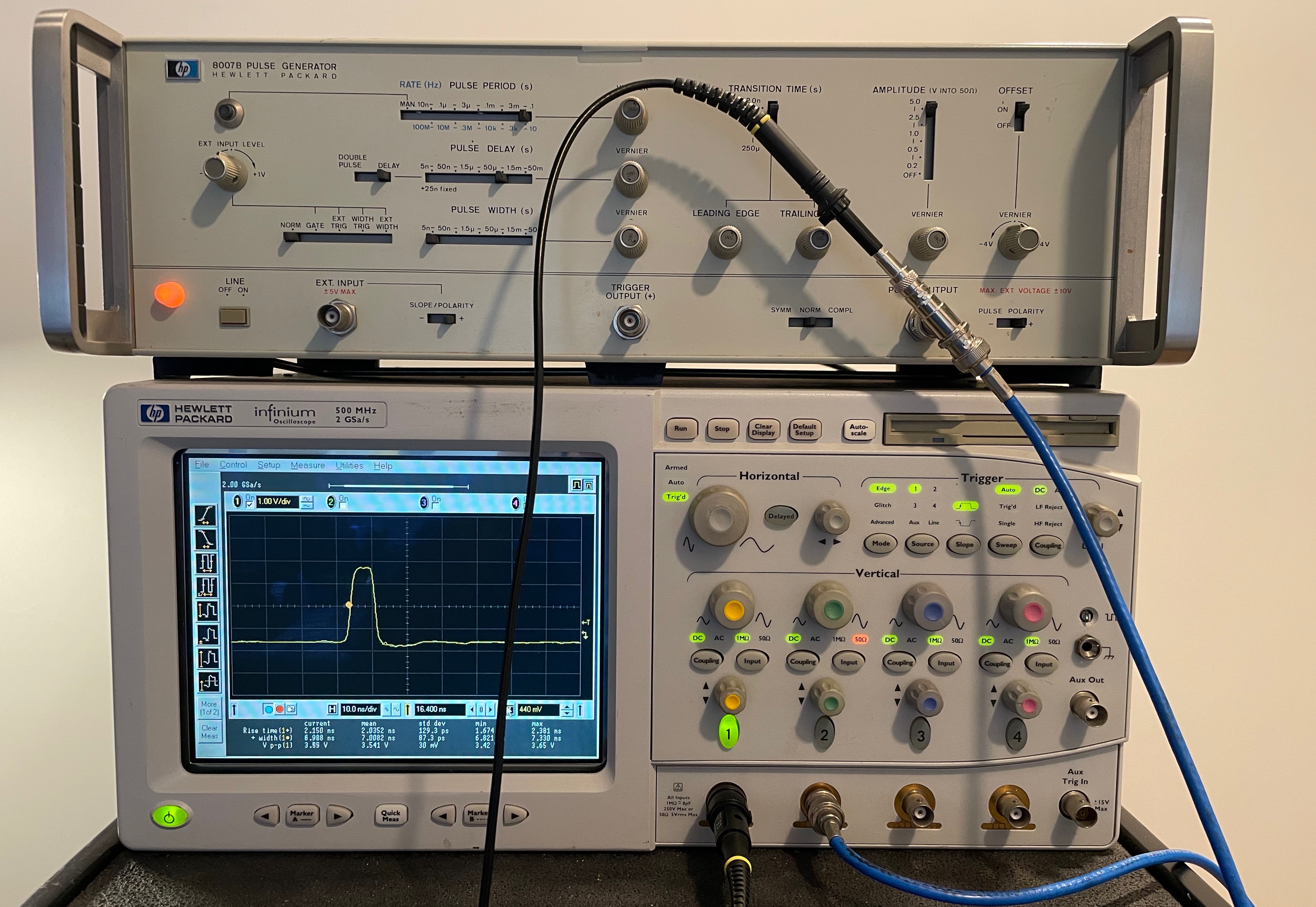
This indefinite-loaner-from-a-friend oscilloscope has a small PC in it that runs an old version of Windows. It can be connected to Ethernet, but I’ve never done that: capturing parallel printer traffic is just too convenient.
On this oscilloscope, I found that printing things out as Encapsulated Postscript was the best option. I then use inkscape to convert the screenshot to PNG:
./fake_printer.py --port=/dev/ttyACM0 -t 2 -v --prefix=hp_osc_ -s eps
inkscape -f ./hp_osc_0.eps -w 1580 -y=255 -e hp_osc_0.png
convert hp_osc_0.png -crop 1294x971+142+80 hp_osc_0_cropped.png
Ignore the part circled in red, that was added in post for an earlier article:
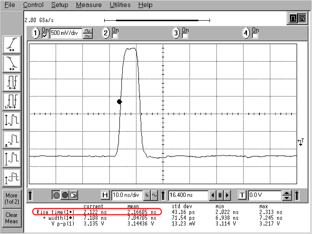 Click to enlarge
TDS 684B - Parallel Port - PCX Color Output
I replaced my TDS 540 oscilloscope with a TDS 684B.
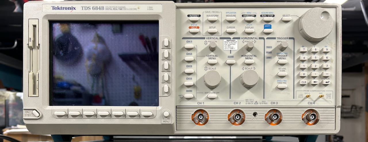
On the outside they look identical. They also have the same core user interface, but the 648B has a color screen, a bandwidth of 1GHz, and a sample rate of 5 Gsps.
Print formats
The 684B also has a lot more output options:
- Thinkjet, Deskjet, DeskjetC (color), Laserjet output in PCL format
- Epson in ESC/P format
- DPU thermal printer
- PC Paintbrush mono and color in PCX file format
- TIFF file format
- BMP mono and color format
- RLE color format
- EPS mono and color printer format
- EPS mono and color plotter format
- Interleaf .img format
- HPGL color plot
Phew.
Like the HP 54542A, my unit has GPIB, parallel port, and serial port. It can also write out the files to floppy drive.
So which one to use?
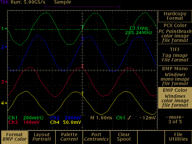
BMP is an obvious choice and supported natively by all modern PCs. The only issue is that it gets written out without any compression so it takes over 130 seconds to capture with fake printer. PCX is a very old bitmap file format, I used it way back in 1988 on my first Intel 8088 PC, but it compresses with run length encoding which works great on oscilloscope screenshots. It only take 22 seconds to print.
I tried the TIFF option and was happy to see that it only took 17 seconds, but the output was monochrome. So for color bitmap files, PCX is the way to go. The recipe:
~/projects/fake_parallel_printer/fake_printer.py -i -p /dev/ttyACM0 -f tds684_ -s pcx -v
convert tds684_0.pcx tds684.png
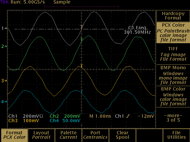
The screenshot above uses the Normal color setting. The scope also has a Bold color setting:
There’s a Hardcopy option as well:
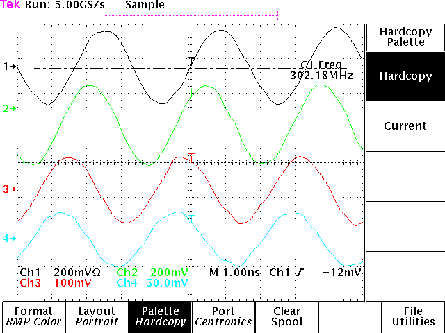
It’s a matter of personal taste, but my preference is the Normal option.
Advantest R3273 Spectrum Analyzer - Parallel Port - PCL Output
Next up is my Advantest R3273 spectrum analyzer.
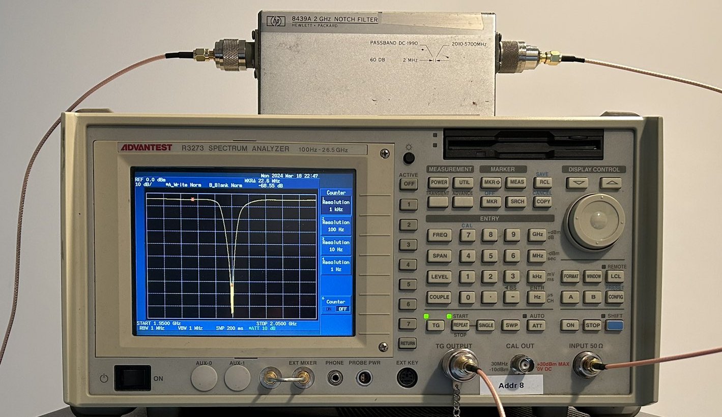
It has a printer port, a separate parallel port that I don’t know what it’s used for, a serial port, a GPIB port, and floppy drive that refuses to work. However, in the menus I can only configure prints to go to floppy or to the parallel port, so fake parallel printer is what I’m using.
The print configuration menu can be reached by pressing: [Config] - [Copy Config] -> [Printer]:
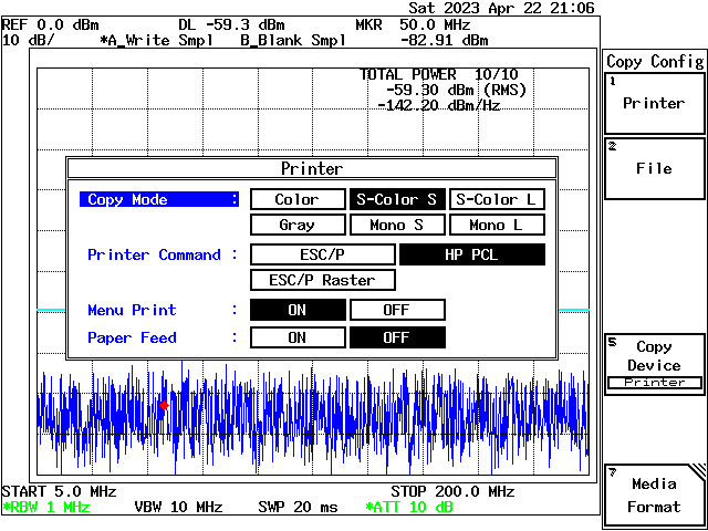
The R3273 supports a bunch of formats, but I had the hardest time getting it to create a color bitmap. After a lot of trial and error, I ended up with this:
~/projects/fake_parallel_printer/fake_printer.py -i -p /dev/ttyACM0 -f r3273_ -s pcl -v
gpcl6 -dNOPAUSE -sOutputFile=r3273_tmp.png -sDEVICE=png256 -g4000x4000 -r600x600 r3273_0.pcl
convert r3273_tmp.png -filter point -resize 1000 r3273_filt.png
rm r3273_tmp.png
convert r3273_filt.png -crop 640x480+315+94 r3273.png
rm r3273_filt.png
The conversion loses something in the process. The R3273 hardcopy mimics the shades of depressed buttons with a 4x4 pixel dither pattern:
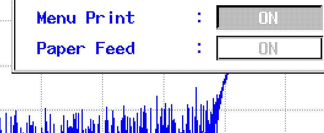
If you use a 4x4 pixel box filter and downsample by a factor of 4, this dither pattern converts to a nice uniform gray, but the actual spectrum data gets filtered down as well:

With the recipe above, I’m using 4x4 to 1 pixel point-sampling instead, with a phase that is chosen just right so that the black pixels of the dither pattern get picked. The highlighted buttons are now solid black and everything looks good.
HP 8753C Vector Network Analyzer - GPIB - HP 8753 Companion
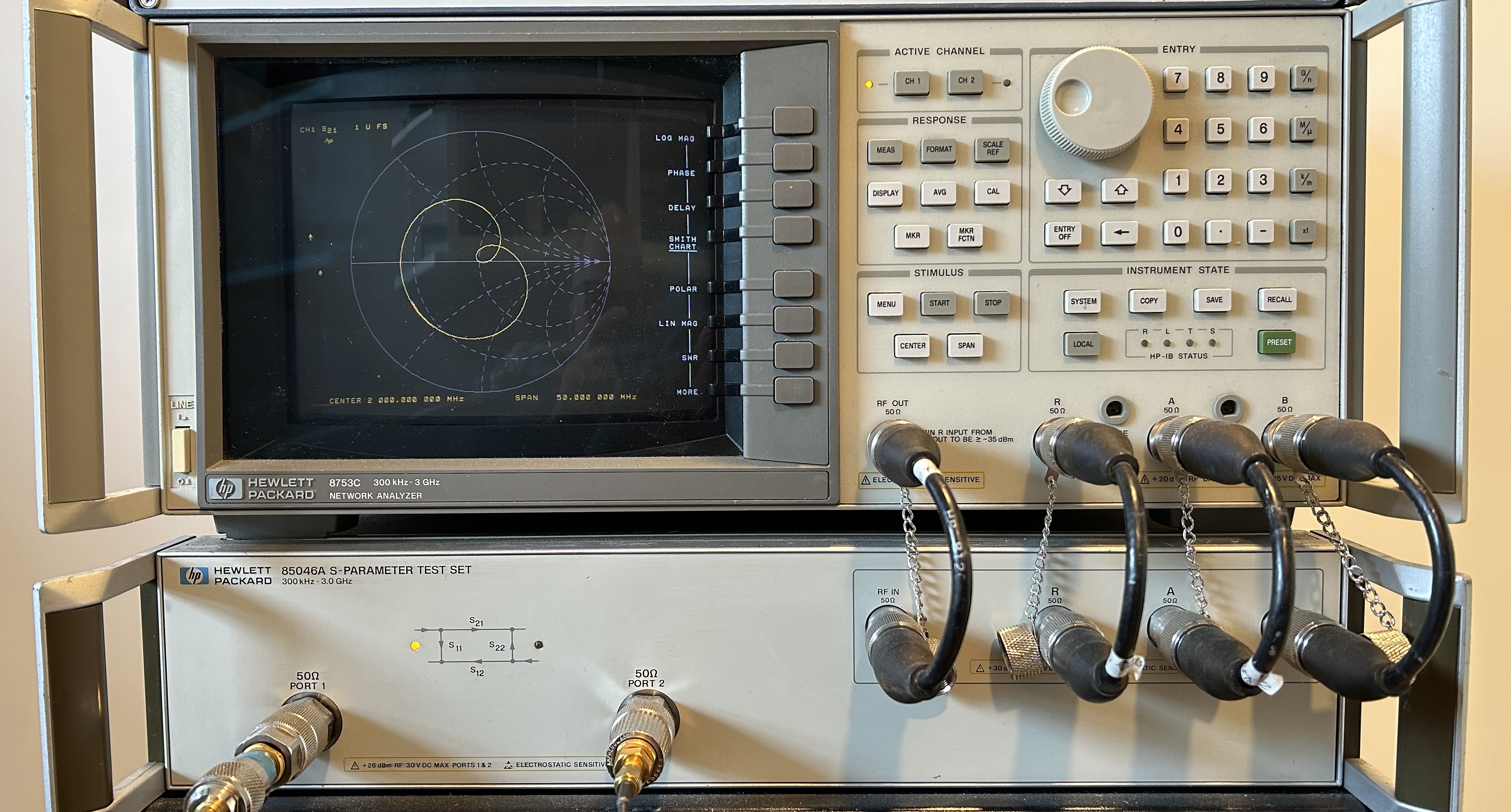
My HP 8753C VNA only has a GPIB interface, so there’s not a lot of choice there.
I’m using HP 8753 Companion. It can be used for much more than just grabbing screenshots: you can save the measured data to a filter, upload calibration kit data and so on. It’s great!
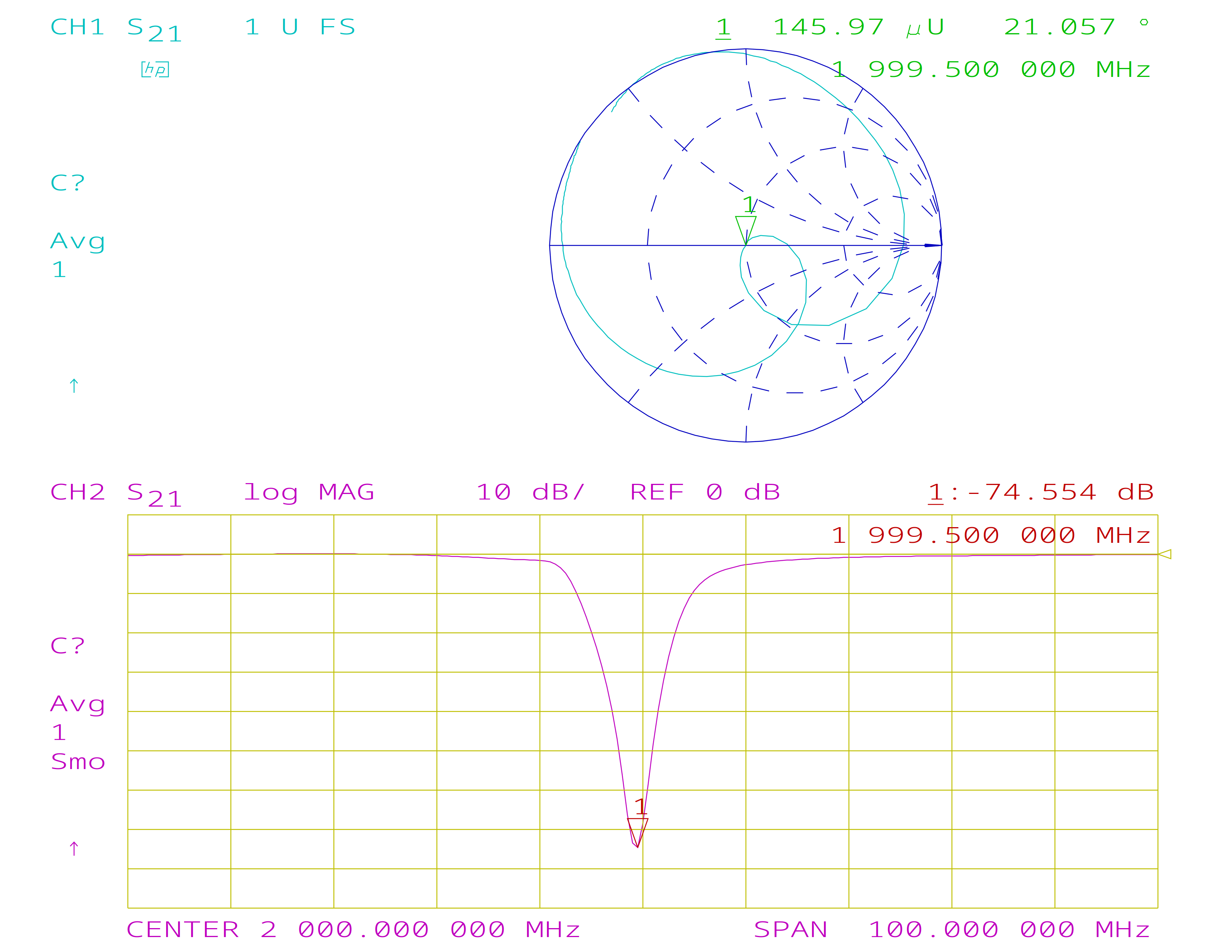
You can render the screenshot the way it was plotted by the HP 8753C, like this:
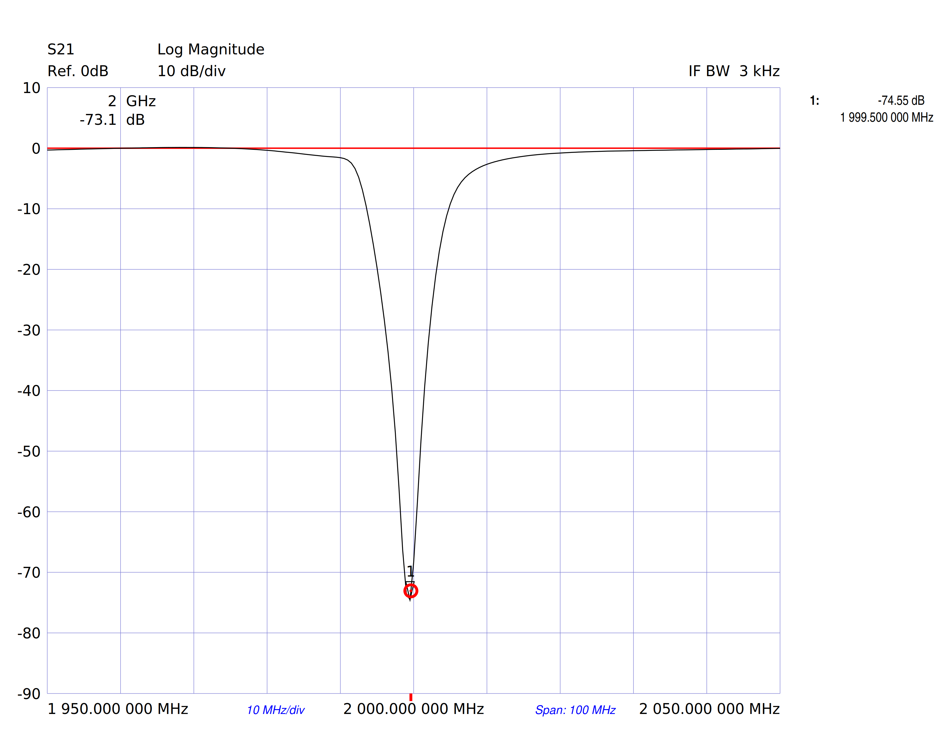
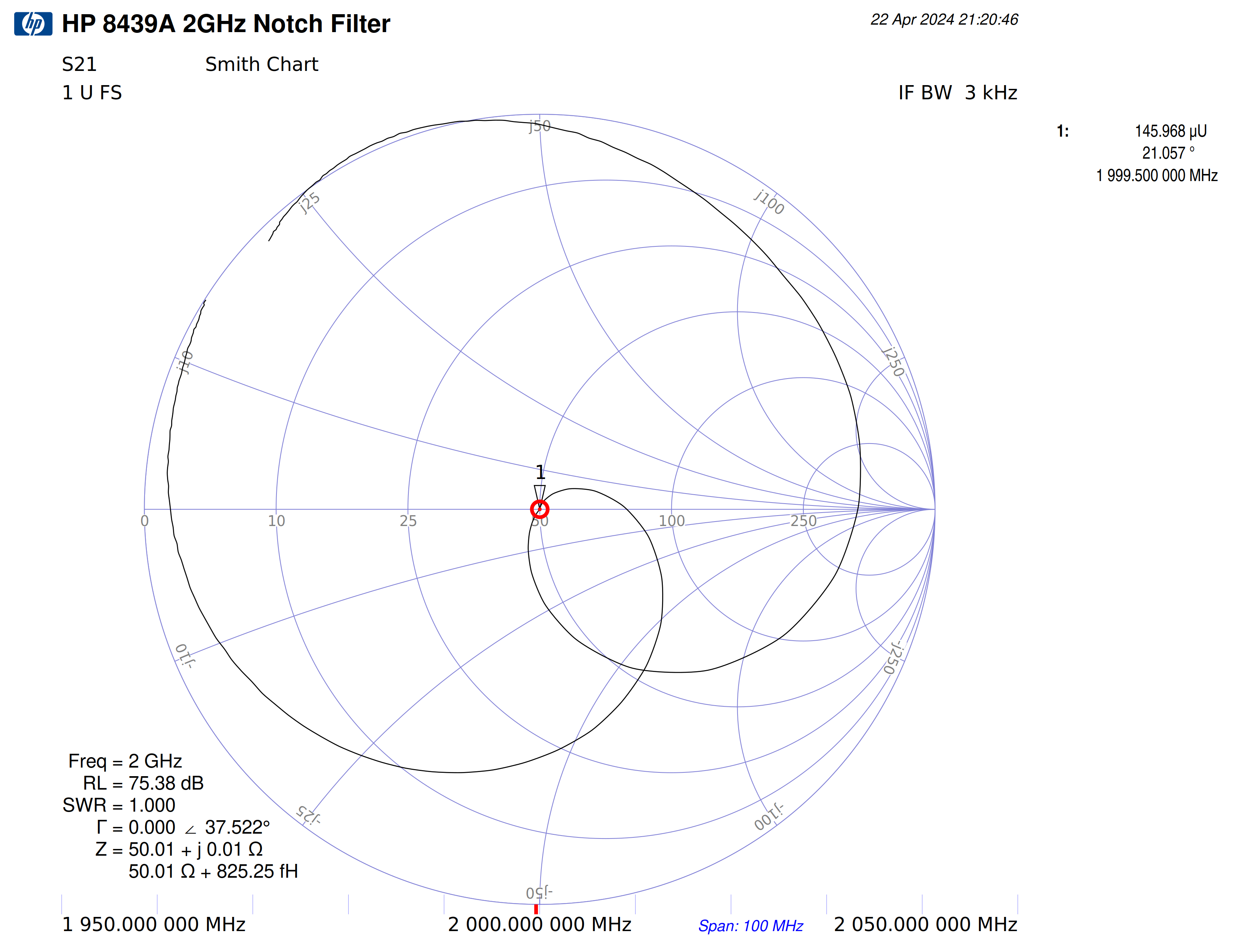
Or you can display it as in a high resolution mode, like this:
Default color settings for the HPGL plot aren’t ideal, but everything is configurable.
If you don’t have one, the existence of HP 8753 Companion alone is a good reason to buy a USB-to-GPIB dongle.
Siglent SDS 2304X Oscilloscope - USB Drive, Ethernet or USB
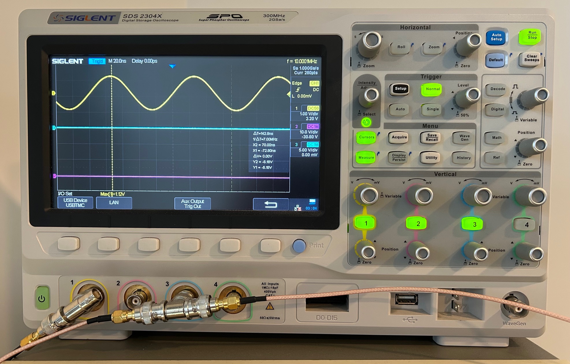
The Siglent SDS 2304X was my first oscilloscope. Designed 20 years later than all the other stuff, it has a modern UI and modern interfaces such as USB and Ethernet. There is no GPIB, parallel or RS-232 serial port to be found.
I don’t love the scope. The UI slows down when you’re displaying a bunch of data on the screen and selecting something from a menu with an overly sensitive detentless rotary knob can be the most infuriating experience. But it’s my daily driver because it’s not a boat anchor: even on my messy bench I can usually create room to put it down without too much effort.
You’d think that I use USB or Ethernet to grab screenshots, but most of the time I just shuttle a USB stick back and forth between the scope and the PC. That’s because setting up the connection is always a bit of pain. However, if you insist, you can set things up this way:
Ethernet
To configure Ethernet, you need to go to [Utility] -> [Next Page] -> [I/O] -> [LAN].
Unlike my HP 1670G logic analyzer, the Siglent supports DHCP but when writing this blog post, the scope refused to grab an IP address on my network. No amount of rebooting, disabling and re-enabling DHCP helped.
I have gotten it to work in the past, but today it just wasn’t happening. You’ll probably understand why using a zero-configuration USB stick becomes an attractive alternative.
USB
For USB, you need an old relic of a USB-B cable. After plugging it in, it shows up like this:
sudo dmesg -w
[314170.674538] usb 1-7.1: new full-speed USB device number 11 using xhci_hcd
[314170.856450] usb 1-7.1: not running at top speed; connect to a high speed hub
[314170.892455] usb 1-7.1: New USB device found, idVendor=f4ec, idProduct=ee3a, bcdDevice= 2.00
[314170.892464] usb 1-7.1: New USB device strings: Mfr=1, Product=2, SerialNumber=3
[314170.892469] usb 1-7.1: Product: SDS2304X
[314170.892473] usb 1-7.1: Manufacturer: Siglent Technologies Co,. Ltd.
[314170.892476] usb 1-7.1: SerialNumber: SDS2XJBD1R2754
Note 3 key parameters:
- USB vendor ID: f4ec
- USB product ID: ee3a
- Product serial number: SDS2XJBD1R2754
Set udev rules so that you can access this USB device without requiring root permission by
creating an /etc/udev/rules.d/99-usbtmc.rules file and adding the following line:
SUBSYSTEM=="usb", ATTR{idVendor}=="f4ec", ATTR{idProduct}=="ee3a", MODE="0666"
You should obviously replace the vendor ID and product ID with the one of your case.
Make the new udev rules active:
sudo udevadm control --reload-rules
sudo udevadm trigger
You can now download screenshots with the following script:
siglent_screenshot_usb.py: (Click to download)
#!/usr/bin/env python3

import argparse
import io
import pyvisa
from pyvisa.constants import StatusCode

from PIL import Image

def screendump(filename):
    rm = pyvisa.ResourceManager('')

    # Siglent SDS2304X
    scope = rm.open_resource('USB0::0xF4EC::0xEE3A::SDS2XJBD1R2754::INSTR')
    scope.read_termination = None

    scope.write('SCDP')
    data = scope.read_raw(2000000)
    image = Image.open(io.BytesIO(data))
    image.save(filename)
    scope.close()
    rm.close()

if __name__ == '__main__':

    parser = argparse.ArgumentParser(
        description='Grab a screenshot from a Siglent DSO.')
    parser.add_argument('--output', '-o', dest='filename', required=True,
        help='the output filename')

    args = parser.parse_args()
    screendump(args.filename)
Once again, take note of this line
scope = rm.open_resource('USB0::0xF4EC::0xEE3A::SDS2XJBD1R2754::INSTR')
and don’t forget to replace 0xF4EC, 0xEE3A, and SDS2XJBD1R2754 by the correct
USB product ID, vendor ID and serial number.
Call the script like this:
./siglent_screenshot_usb.py -o siglent_screenshot.png
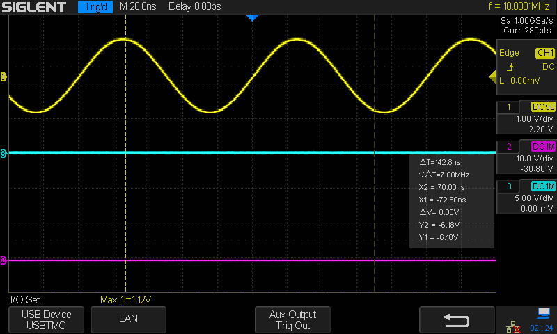
If all goes well, you’ll get something like this:
Footnotes
-
There are some lower cost GPIB dongles available now, and there’s even an open source one that you can build yourself. I haven’t tried any of those though. ↩
