Fake Parallel Printer - A Parallel Port Traffic Capturing Tool
- Introduction
- What Is Out There?
- The Parallel Printer Port
- Fake Printer Top Level Design Choices
- Fake Printer HW Details
- PCB Revision 1
- PCB Revision 2
- Firmware
- Building a Fake Printer Tool Yourself
- Programming the Raspberry Pico
- Fake Printer as a USB Serial Device on your PC
- Capturing Parallel Printer Data with fake_printer.py
- Coming Soon: Converting a Printer Capture to a Bitmap
- Printed case
- References
Introduction
My previous blog post contained a screenshot of an Advantest R3273 spectrum analyzer that I took by holding my iPhone in front of the screen:
Using a camera works, of course, but it doesn’t look very… professional?
Here’s another one from my TDS 420A blog posts:
This one looks even worse, because the CRT hasn’t been tuned quite right and the image is rotated a little bit.
What I want is a bit-for-bit hard-copy of what’s shown on the screen, like this:
or this:
Much better!
It’s easy to save screenshots on modern equipment. On my daily driver Siglent oscilloscope, the easiest way is to just insert a USB stick and press “Print”, but you can also do it by scripting some SCPI commands over a USB or Ethernet connection:
 (Click to enlarge)
It’s not so simple for old equipment. The TDS 420A and the R3273 have a GPIB interface that can be used to download raw measurement data, but not the screen contents, menus and all included. However, they do have a floppy drive to save screenshots, and there’s an old school parallel port to send a screenshot straight to a printer.
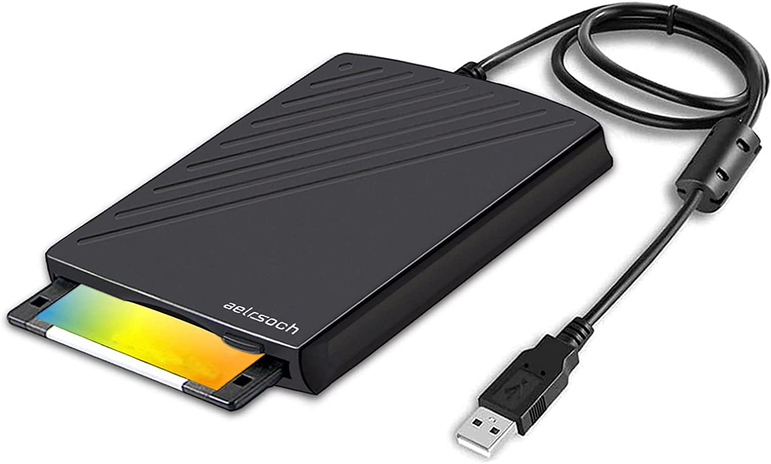
I bought a floppy drive on Amazon for $19 and spent an additional $18 for a pack of 10 3 1/2 HD floppy disks, only to discover that the floppy drives on both instruments were broken. Maybe that’s just to be expected from equipment that’s 20 to 30 years old…
So the only interface left is the parallel printer port. Which made me think: “What if I capture the printer data and convert it into a bitmap on my PC?” And thus a new project was born!
What Is Out There?
I’m certainly not the first one to think about this. For £90, around $110, Retro-Printer claims to do exactly what I want.

It’s a Raspberry Pi hat that plugs into, well, a Raspberry Pi which is fine if you have one laying in a drawer somewhere, otherwise it’s another $100+ in today’s crazy market. Retro-Printer has been in existence for a while and they have dedicated software to back it, some open source, some not. I didn’t test it, but if you want something that’s a real product instead of a quick weekend hack, it’s probably the option with the highest chance of success.
Still, it’s a little too much for what is, in my case, a non-essential gadget that I’ll use only a few times per year.
I asked for feedback on Twitter and got a number of useful pointers.
Rue Mohr created one by soldering a connector and an Atmega on perfboard. It looks really neat:
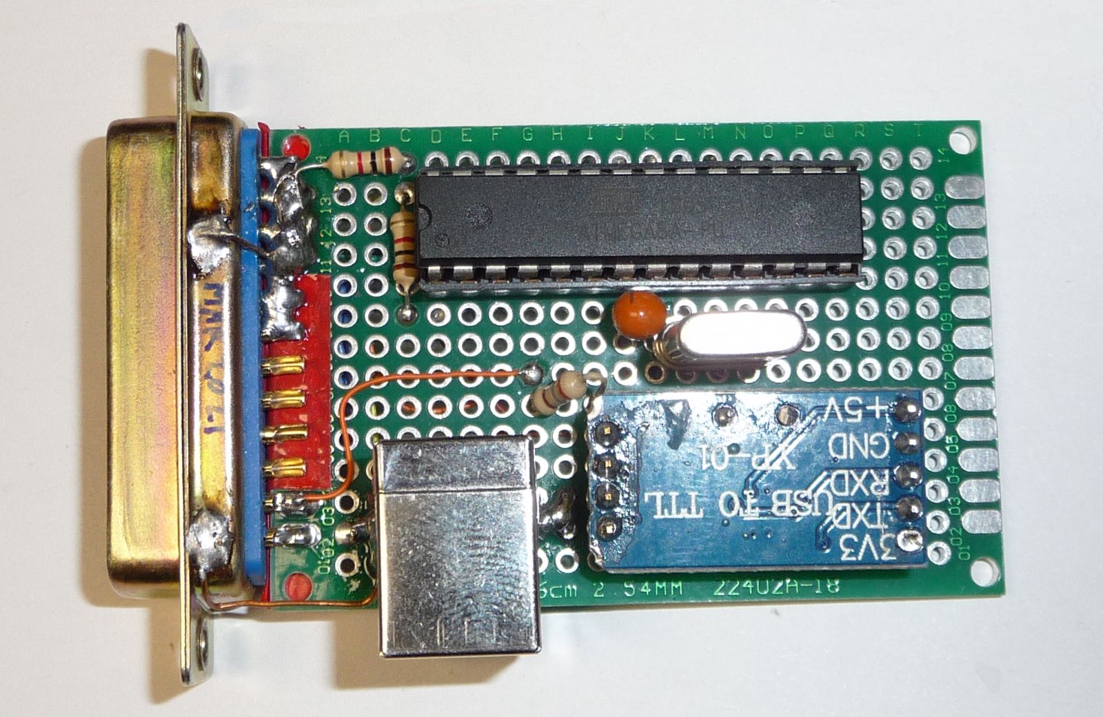
He also shared his Parallel2Serial repo on GitHub with the Atmega firmware.
There are other projects out there, but when you google for terms such as “parallel port to usb”, they drown in a sea of “USB to parallel port” results!
The Parallel Printer Port
Protocol
The parallel printer port and associated protocol was originally defined by Centronics way back in 1970 for their Model 101 printer. The Vintage Technology Digital Archive still has the specification and interface information for it.
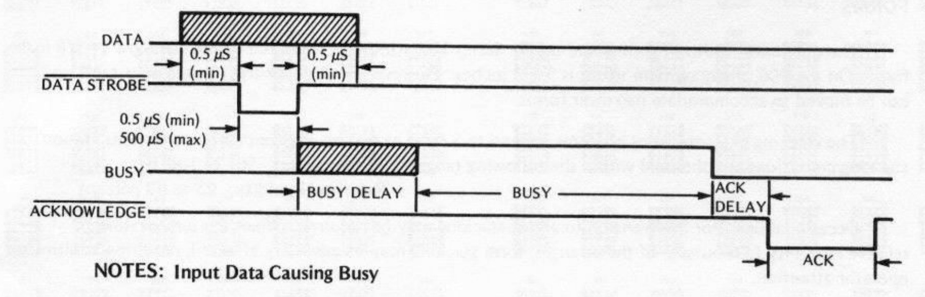
The diagram shows how a BUSY signal gets asserted by the printer when it’s doing certain long duration activities such a line or a paper feed, but the signal is frankly a bit redundant, as we shall soon see.
Either way, these are the signals that actively participate in data transactions:
| Name | Direction | Description |
|---|---|---|
| nSTROBE | To Printer | A low pulse indicates that there’s valid data on D[7:0]. This pulse can be as short as 500ns. |
| D[7:0] | To Printer | The data that is transmitted to the printer. The data is valid when nSTROBE is low. |
| BUSY | To Host | Inform the host that the printer is busy and that it should wait with sending the next data. |
| nACK | To Host | A low pulse tells the host that the current data has been processed. |
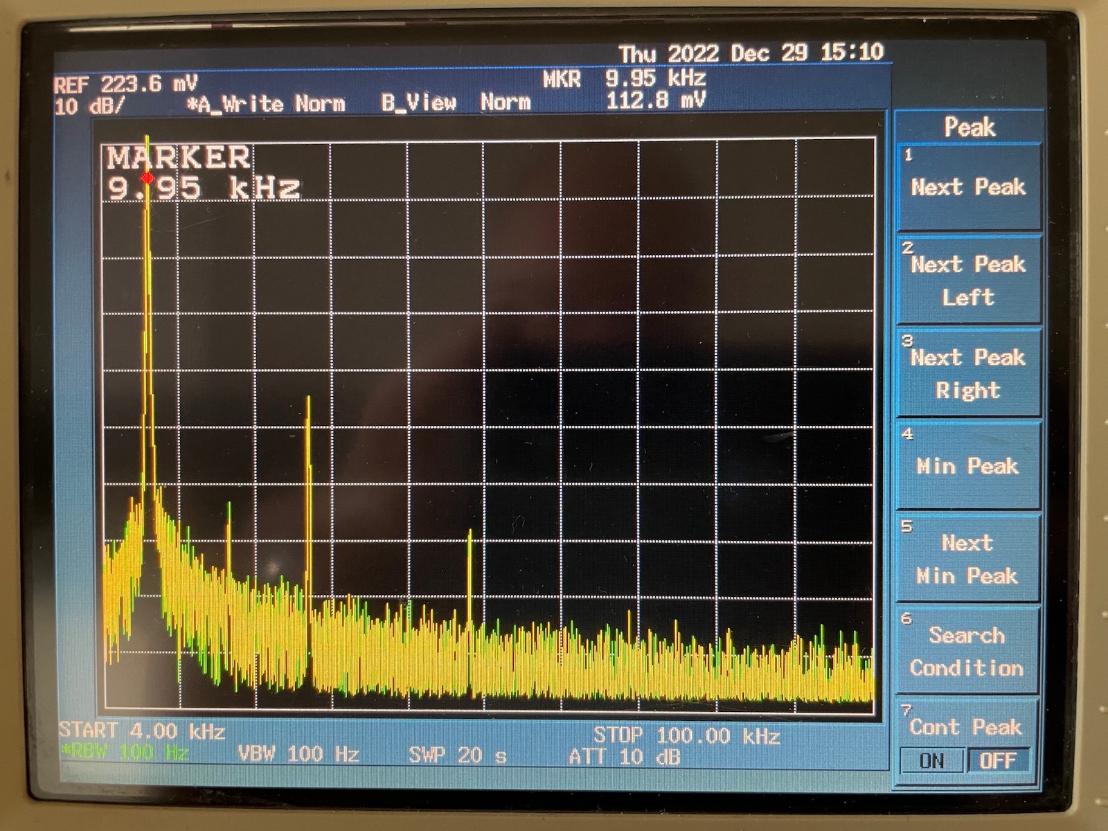
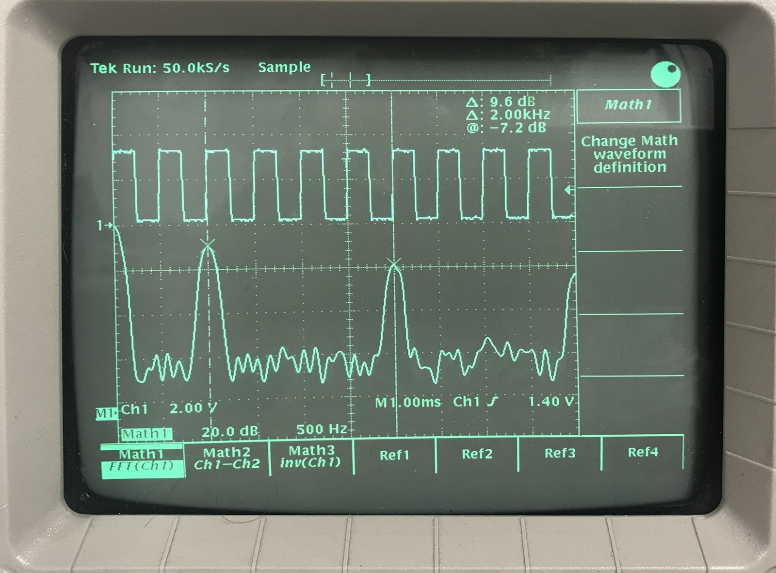
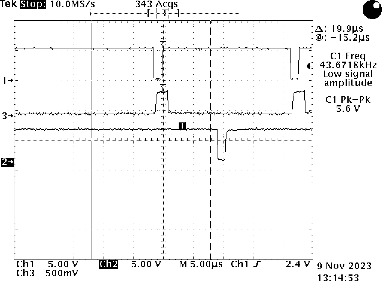
Here is parallel port traffic between the spectrum analyzer and the fake printer:
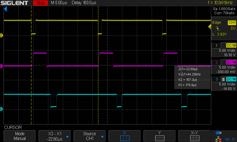 nSTROBE: yellow, BUSY: purple, nACK: cyan
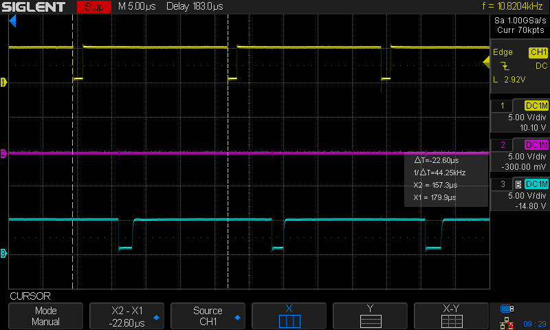
There’s 22uS between each transaction, good for a data rate of around 350kbits/s, but most instruments don’t come close to that.
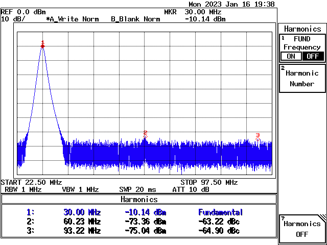
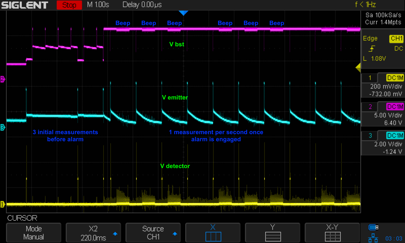
I created a test firmware for fake printer that never asserts BUSY. It works just the same, showing that the R3272 probably ignores BUSY and simply waits for an end-of-transaction nACK pulse:
Unfortunately, things are not that easy in the real world. After publishing this blog post, I found out that the parallel port on an HP Infinium oscilloscope behave in unexpected ways:
- when the printer doesn’t assert BUSY in time, it will simply continue pulsing nSTROBE without even checking for nACK!
- when you do assert BUSY and the deassert it, it doesn’t check nACK either.
I think that the oscilloscope switches to a more advanced parallel port mode without first going through the negotiation step to switch out of compatibility mode. Either way, the firmware currently makes sure that BUSY gets asserted as soon as possible after asserting of nSTROBE. It also asserts nACK immediately after BUSY, without inserting a waiting time. This seems to make thing work for the 3 devices that I have.
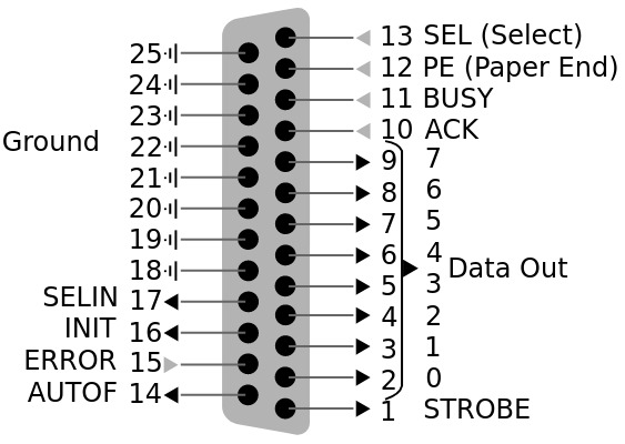
In addition to the signals that are used for the actual data transfer, the parallel port has a bunch of mostly static control and status signals:
| Name | Direction | Value | Description |
|---|---|---|---|
| nINIT | To Printer | 1 | A negative pulse resets the printer to its default state. |
| nSELINT | To Printer | 0 | A low value tells the printer that a host is present and powered on. |
| nAUTOF | To Printer | 1 | No strict definition. A low value is used to perfrom things like printer auto-feed or some other action. |
| SEL | To Host | 1 | A high value indicates that a printer is present. |
| PE | To Host | 0 | Short for Paper Error. A high value indicates that the printer can’t print at this time. |
| nERROR | To Host | 1 | A low value indicates that the printer has encountered some kind of error. |
For a simple traffic capturing tool, you can ignore the 3 signals that are going to the printer and you can tie the signals that go back to the host to the listed static values.
The parallel printer port was originally only used for low speed printer communication, but it was later upgraded to support higher transfer speeds and even bidirectional data communication. These extensions are described in the IEEE 1284 specification which defines different modes: compatibility mode, nibble mode, byte mode, enhanced parallel port (EPP), and extended capability port (ECP), where compatibility mode is the original protocol.
After powering up, all printers start out in compatibility mode. They switch to a different mode through a protocol negotiation process.
For our purposes, we can ignore all these advanced modes and stick with compatibility mode.
Connectors
The host almost always uses a DB-25 connector:
Source: Wikipedia, (c) Andrew Buck
The printer side has a 36-pin Centronics connector:
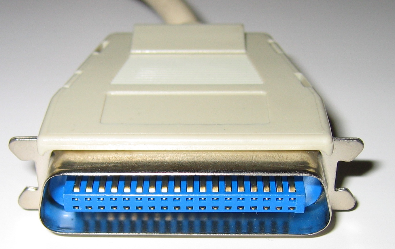
Source: Wikipedia, (c) Michael Krahe
Fake Printer Top Level Design Choices
Here’s a executive summary of the fake printer features and design decisions:
- DB-25 connector on a PCB that plugs straight into the instrument
- USB acting as serial port to transmit captured data to the PC
- Raspberry Pico as microcontroller
DB-25 instead of Centronics Connector
The Retro-Printer solution has a Centronics port, just like a real printer. I’m using DB-25 connector instead. The reason is cost and, IMO, convenience. On Digikey, the DB-25 connector is $1.60 versus $7.10 for the Centronics one. And if you use the Centronics connector, you need a bulky DB-25 to Centronics cable too, good for an additional $12! And now you have 2 cables to deal with: the printer cable and the USB cable from the fake printer back to your PC.
Raspberry Pico
You can see by looking at Rue’s design that a fake parallel printer can be very simple. You need to have:
- a parallel interface that can deal with 5V signalling in transmit and receive direction
- logic to reliably capture the 8-bit data and adhere to the parallel port protocol
- a way to interface with the PC. USB is the obvious choice here.
In this day and age, you use a microcontroller for stuff like this. Rue had an Atmel in his component box, which is great because it has USB device interface and 5V capable IOs right out of the box.
I choose a Raspberry Pico because:
- I had a couple laying around
- at around $5 a piece, they’re cheap enough
- they are staightforward to program and to program for
- they are available everywhere in high volume: no issues with component shortage!
The Raspberry Pico is bulkier than smaller alternatives with the same RP2040 silicon, such as the Seeed Studio XIAO RP2040, but in my final PCB design that doesn’t make a practical difference. And the Pico is the reference implementation which should be available for as long as the RP2040 exists.
Instead of a Pico, you can also use a Pico W. The boards are pin compatible after all. A wireless interface can be useful when the back side of your oscilloscope is hard to reach, but you’d still need a USB cable to power the board because there is no +5V pin on the parallel port itself.
Fake Printer HW Details
Level Shifter
Since a Raspberry Pico doesn’t have 5V tolerant IOs, one or more buffer ICs are required for level shifting.
My initial design used 3 generic SN74LVC8T245PW 8-bit transceivers that cost $1.65 a piece on Digikey. Only once that PCB layout was completed did I check if by any chance there was a buffer IC that is specifically designed for the parallel port. There was, of course: the 74LVC161284 is that chip, and it’s yours for only $2.08.
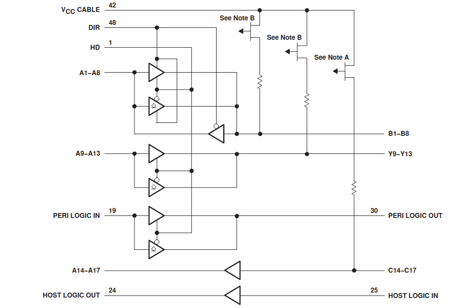
If you have been keeping track, there are a total of 17 parallel port signal listed in the previous section. Consequently, the 74LVC161284 has 17 main signals as well, going in the right direction. Since the chip can support the later IEEE 1284 protocols, the IOs for the databus are bidirectional.
You can ignore the PERI_LOGIC and HOST_LOGIC feed-through signals: they are not used.
Resistors and Caps
The service manual of a Sharp AR-PK11 laser copier/printer contains the full schematics and uses an 74LVC161284. Useful to check what kind of surrounding components are used in a real implementation:
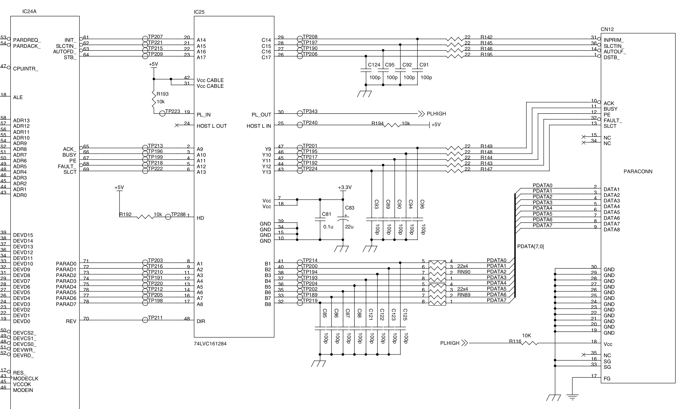 (Click to enlarge)
The schematic has 22 Ohm resistors on each of the 17 signals to dampen reflections on the cable. These are probably overkill on a design that doesn’t have a cable, but I added them anyway. Same thing for 17 100pF capacitors, which I added to the design and the PCB but didn’t solder on the actual board.
Ready for Full IEEE-1284 Support
For a minimal parallel printer emulation, you can safely ignore the nINIT, nAUTOF, and nSELIN signals that are coming from the host, and the nERROR, PE, and SEL signals that from the printer back to the host can be strapped to a fixed value.
But by connecting all of these signals to the Raspberry Pico, you retain the option to support IEEE-1284 mode that are more than just compatibility mode.
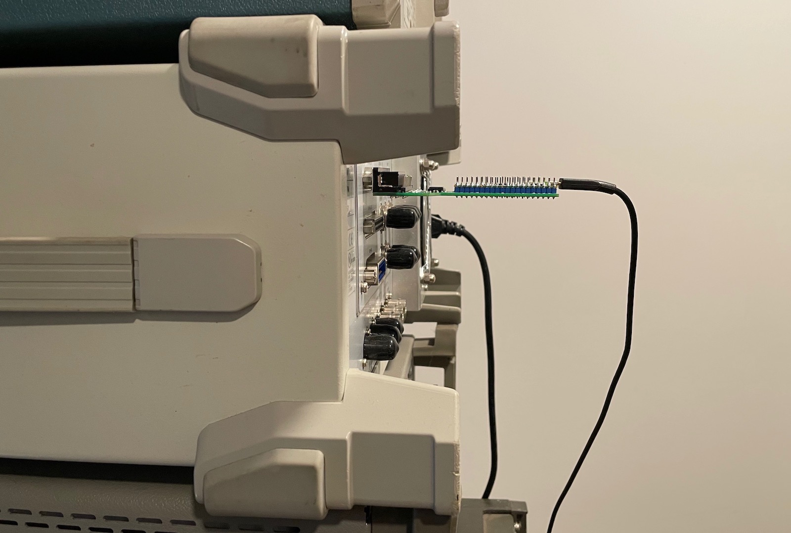
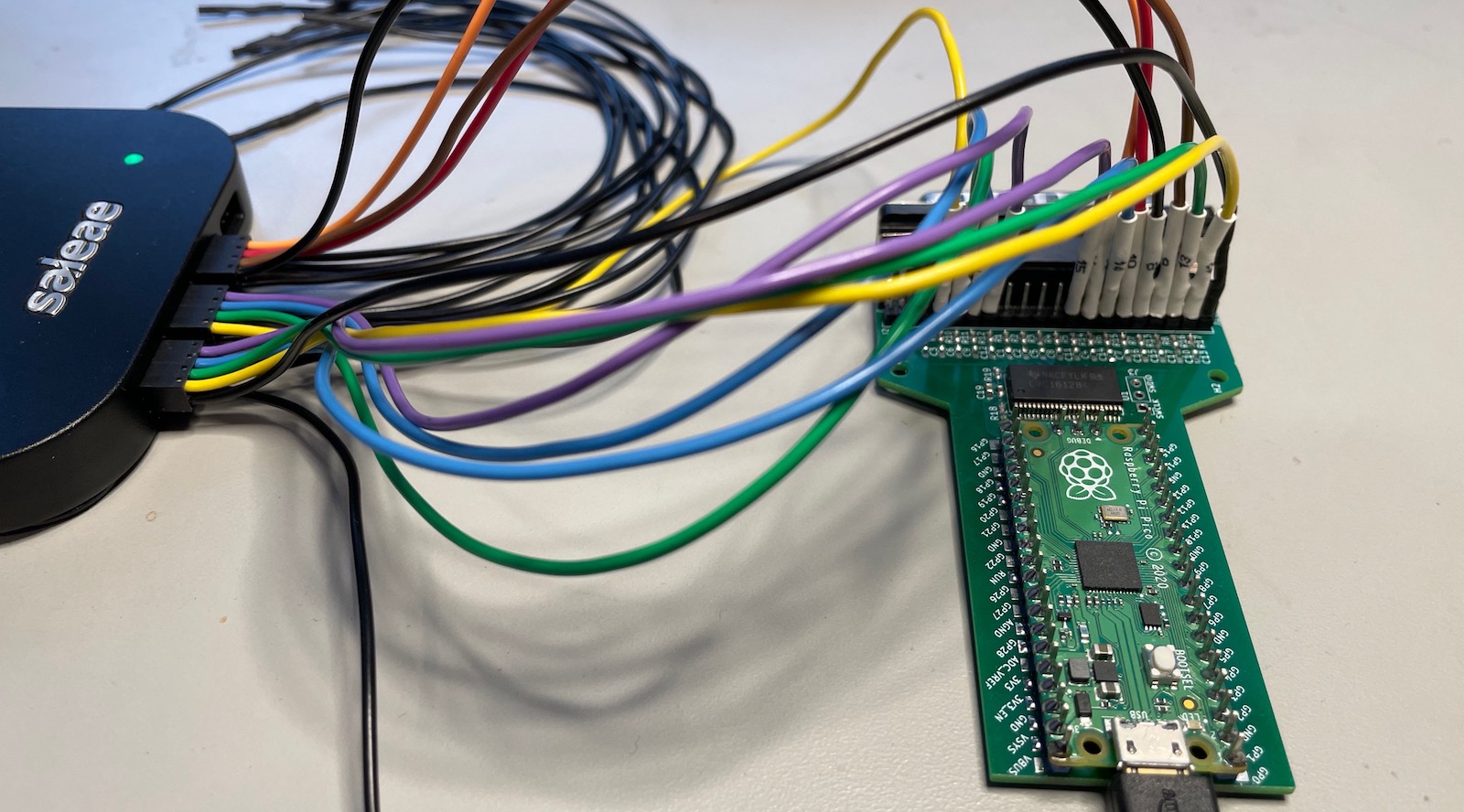
Test Pins
While designing the PCB, I wasn’t 100% sure how different instruments would behave, and I wanted to make sure that it’d be easy to capture the bus signals with a logic analyzer. I’m happy that I did, it’s one of those things that makes your life a lot easier!
PCB Revision 1
The first version of the PCB was designed with KiCAD 6. You can find the full design database in the fake_parallel_printer repo on GitHub.
The schematic is about as straightforward as you can imagine.
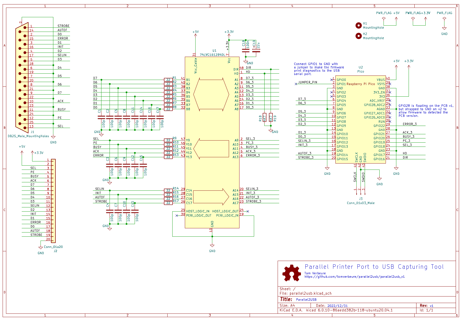 (Click to enlarge)
And here’s the PCB:
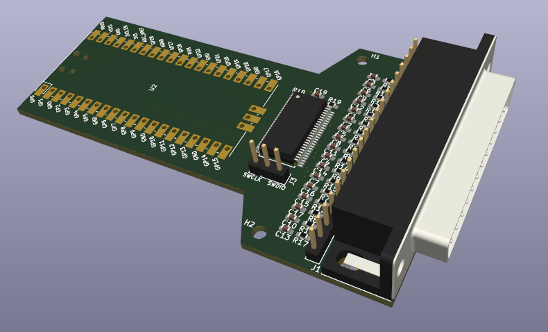
A zip archive with the Gerber files can be uploaded straight to JLCPCB.
For once I didn’t make any mistakes: the board worked fine.
However, after everything was complete, there were 2 things that bugged me:
-
the form factor isn’t practical
It’s way too long, especialy if you factor in the USB cable that’s sticking out in the back. Space on the lab bench is often at a premium and shouldn’t be wasted.
-
the PCB uses 4 layers for no good reason whatsoever.
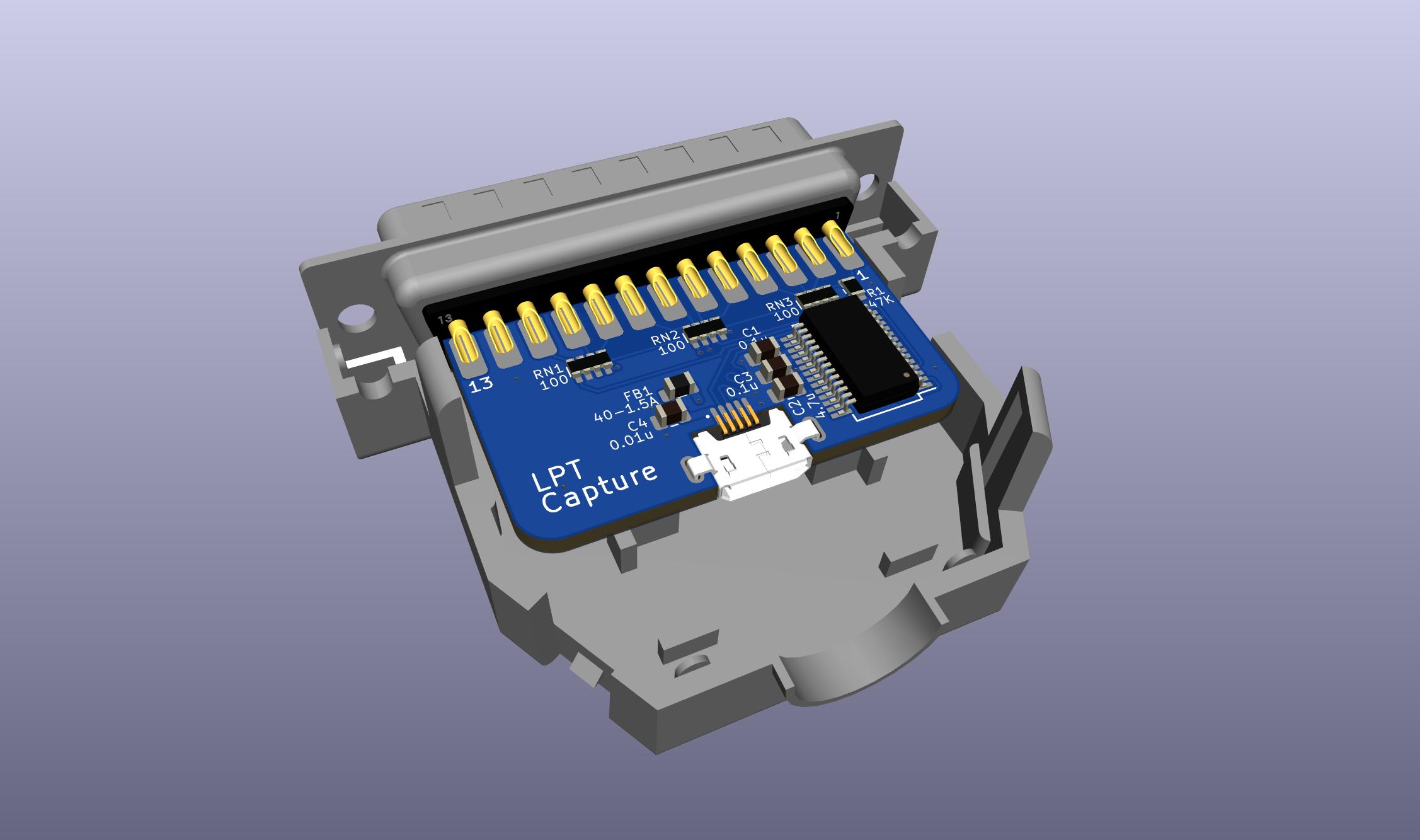
PCB Revision 2
I created a second PCB version that fixes these 2 issues:
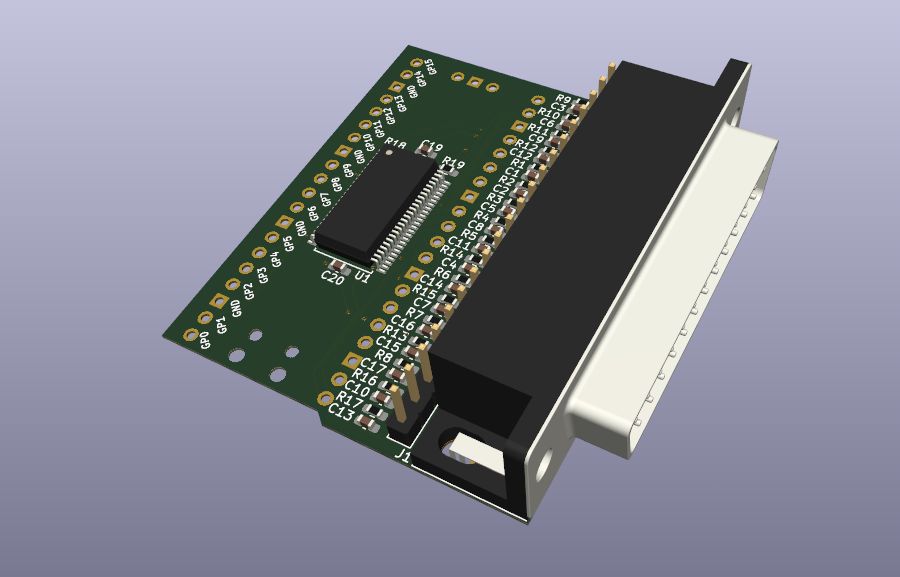
In this version, the Raspberry Pico is mounted at the bottom of the PCB, on the other side of the rest of the components.
The schematic of revision 2 has different pin assigments, and it has 1 additional decoupling cap, but it is otherwise identical. The firmware automatically detects the PCB version and assigns the pin locations accordingly.
Here’s the zip archive for the rev 2 Gerber files.
I haven’t sent out revision 2 for production!
Firmware
The firmware is extremely basic:
- GPIO pin configuration
- Interrupt to detect falling edge of nSTOBE
- Interrupt routine that:
- asserts BUSY,
- read the data pins
- send the byte to the USB serial port
- deassert BUSY
- pulse nACK
That’s really about it.
There’s also a debug function that prints out the number of bytes received on the printer port, and a checksum. You trigger this functionality by putting a jumper (or a button) between GND and the JUMPER_PIN (see schematic) of the Raspberry Pico, but you won’t need to do this if all goes well.
Building a Fake Printer Tool Yourself
Disclaimer: build at your own risk! This is a hobby project. It worked for me, but there are no guarantees that it won’t set the parallel port of your expensive equipment on fire!
You can build a fake printer tool for around $25.
Here’s the cost breakdown of the fake printer tool:
| 5 revision 2 PCBs at JLCPBC | $2 |
| JLCPCB Global Direct Line Saver shipping | $7.25 |
| All components at DigiKey (cart) | $11.17 |
| DigiKey USPS Priority Mail shipping | $5 |
| Total | $25.42 |
JLCPCB prices are variable and subject to frequent special promotional offers.
Shipping cost accounts for ~50% of the total, so you can cut down on that significantly by organizing some kind of group buy.
I think it’s best to solder the components in the following order:
- 74LVC161284
- SMD Resistors and capacitors but not necessarily all of them!
- DB-25 connector
- Raspberry Pico with optional pin-headers
74LVC161284
If you don’t have experience with precision soldering, the hardest part by far is soldering the 74LVC161284 with pins that have a 0.5mm pitch. I did things the traditional way with a fine-tipped soldering iron, applying solder to each pin one-by-one, while using a microscope.
I’ve been told though that drag soldering is really the way to go. Here’s an excellent demonstration of that:
I’ll try it on the next revision.
Resistors and Capacitors
All resistors and caps are using a 0603 HandSolder footprint. It’s the smallest size that I can solder confidently without a microscope.
You don’t have to solder all the resistors: if you’re really in a hurry, you can drop R14, R15 and R16 (for SELIN, nINIT, nAUTOF). The current Raspberry Pico firmware doesn’t use these signals, but you’ll need them if you ever want to implement other IEEE-1284 protocols.
You can save yourself more work by not soldering any of the 17 100pF capacitors. I didn’t and everything worked just fine. The signals looked clean on the oscilloscope as well.
Raspberry Pico
You can solder the Raspberry Pico straight onto the PCB, but I always use a pin header as spacer between the main PCB and the Pico. This makes it so much easier to connect an oscilloscope probe on the Pico pins in case something doesn’t work quite right. If you don’t plan to do any firmware changes, there’s no need to use them.
The 2 20-pin pin headers are not included in the DigiKey component cart!
Connector Debug Pin Header
J2 is another 20-pin pin header that I added to be able to probe the signals as they are present on the DB-25 connector. Same thing as before: no need to add this if you don’t plan on making firmware changes, and this one can always be added later.
This pin header is also not part of the DigiKey cart.
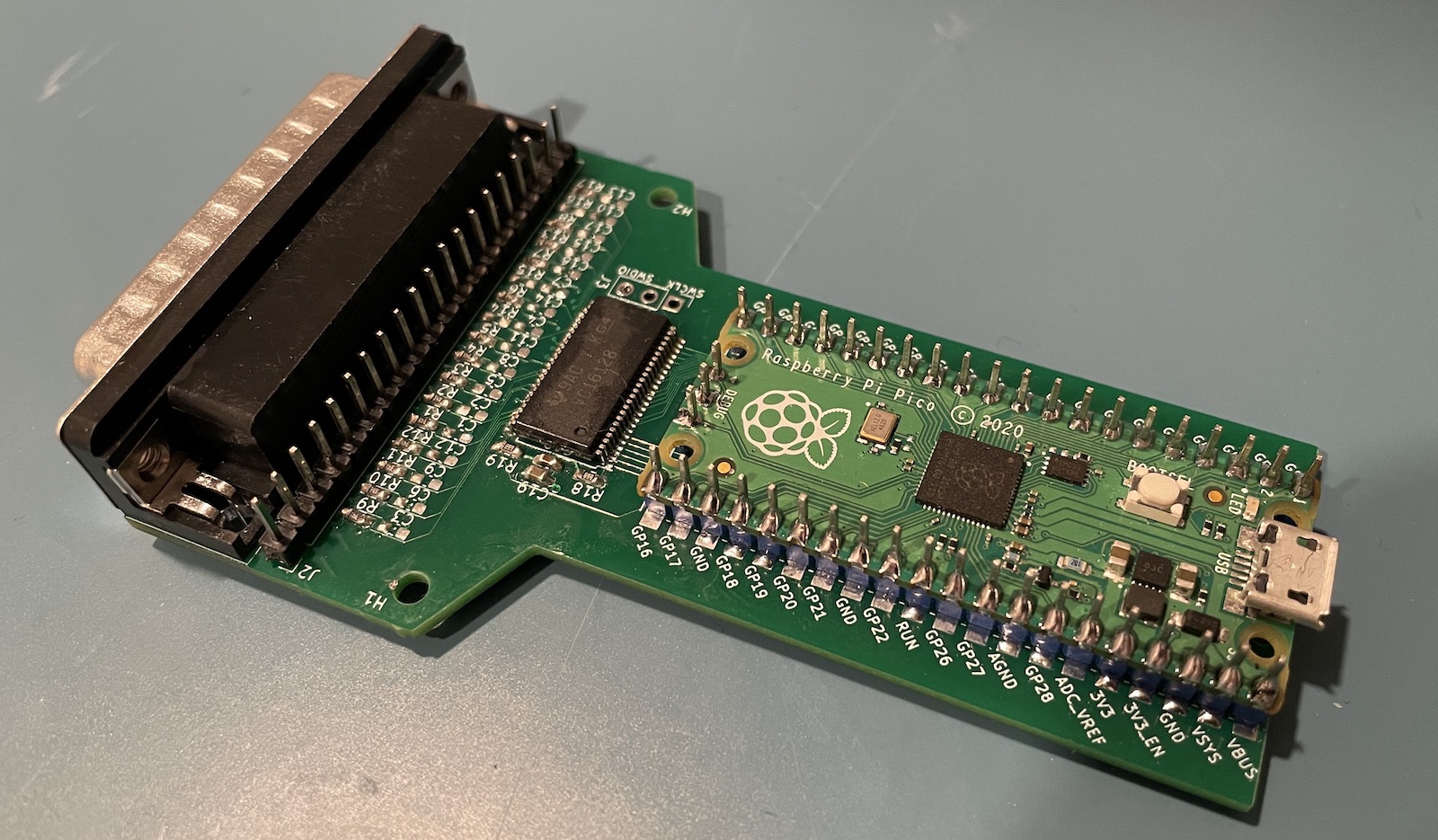
My revision 1 PCB looks like this after assembly:
Programming the Raspberry Pico
Programming the Raspberry Pico with the fake printer firmware is super simple:
- Unplug the USB cable
- Press the BOOTSEL button
- Plug in the USB cable
- Release the BOOTSEL button
- Wait until a USB drive with the name RPi-RP2 shows up on your PC
- Drag the
parallel2usb_hd_on.uf2file onto the RPi-RP2 USB drive.
After one second, you’ll see the green LED on the Raspberry Pico blink twice. Done!
Fake Printer as a USB Serial Device on your PC
After plugging in the USB cable into your PC, there should be a new serial USB device.
Linux
On Linux, this device will show up as /dev/ttyACMx or /dev/ttyUSBx. The value of x will
depend on who many serial devices there are active on your PC. If there’s the only one, then
x will be 0.
If you’re not sure, run dmesg -w in a terminal window, and plug in the USB cable.
You’ll see something like this:
[1041048.447119] usb 1-7.1: new full-speed USB device number 26 using xhci_hcd
[1041048.783246] usb 1-7.1: New USB device found, idVendor=2e8a, idProduct=000a, bcdDevice= 1.00
[1041048.783254] usb 1-7.1: New USB device strings: Mfr=1, Product=2, SerialNumber=3
[1041048.783257] usb 1-7.1: Product: Pico
[1041048.783260] usb 1-7.1: Manufacturer: Raspberry Pi
[1041048.783262] usb 1-7.1: SerialNumber: E66038B713624535
[1041048.809753] cdc_acm 1-7.1:1.0: ttyACM0: USB ACM device     <<<<<<<
The last line shows the device name.
Windows
After plugging in the USB cable, the device should pop up in the Windows Device Manager:
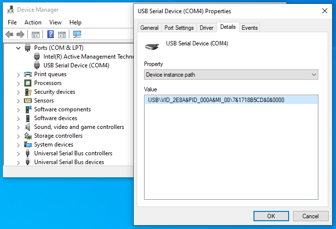
The device name in this case is COM4.
Capturing Parallel Printer Data with fake_printer.py
All that’s left now is storing the captured data on your PC.
Barebones capture on Linux
On Linux, it can be as simple as using the following command line:
(stty -echo raw; cat > screenshot_0.prtcap) < /dev/ttyACM0
The captured data will end up in screenshot_0.eps. If you need to capture multiple screenshots,
you’ll need to abort the command above after each screenshot, increase the number of the filename,
and start it again.
A print operation often happens in the background on your instrument, and there’s no clear indication
when it has completed. I simply check the size of the screenshot_0.eps file with ll -r screenshot*
and abort the capture the file size stays constant.
fake_printer.py
There’s a more user friendly way with fake_printer.py,
which is part of the fake_parallel_printer repo on GitHub.
It’s a Python script that automatically splits print captures into different files when it sees the parallel port going idle for a couple of seconds. It also provides feedback about printer data being received.
To use it, first make install the Python pyserial module:
pip3 install pyserial
After that, you can run fake_printer.py. At the very minimum, you need to provide the USB serial drive
name:
On Linux:
./fake_printer.py --port=/dev/ttyACM0
or on Windows:
./fake_printer.py --port=COM4
Here’s the output on my screen when capturing a TDS 420A screenshot:
tom@zen:~/projects/parallel2usb$ ./fake_printer.py -v -p /dev/ttyACM0
fake printer:
    verbose = True
    port    = /dev/ttyACM0
    timeout = 2
    prefix  = printer_capture_
    suffix  = prtcap
    page nr = 0
Printer data received. Creating printer capture file printer_capture_0.prtcap.
...............................................
48485 bytes received in 18s. (2634 bytes/s)
No printer data received for 2 seconds. Closing printer capture file.
Coming Soon: Converting a Printer Capture to a Bitmap
This blog post covered building and using Fake Printer. The next step is converting captured printer data to something usable, a bitmap or a PDF file. Depending on the available and chosen format, ESC/P, PCL, etc, that process can be quite painful. It will be convered in a future blog post.
If you can’t wait, you can find the key points in Converting a Parallel Port Captured File.
Printed case
A year later…
I never got around producing the PCB for version 2, and probably never will, but I’m using v1 all the time. And my friend Joshua created a 3D printed enclosure!
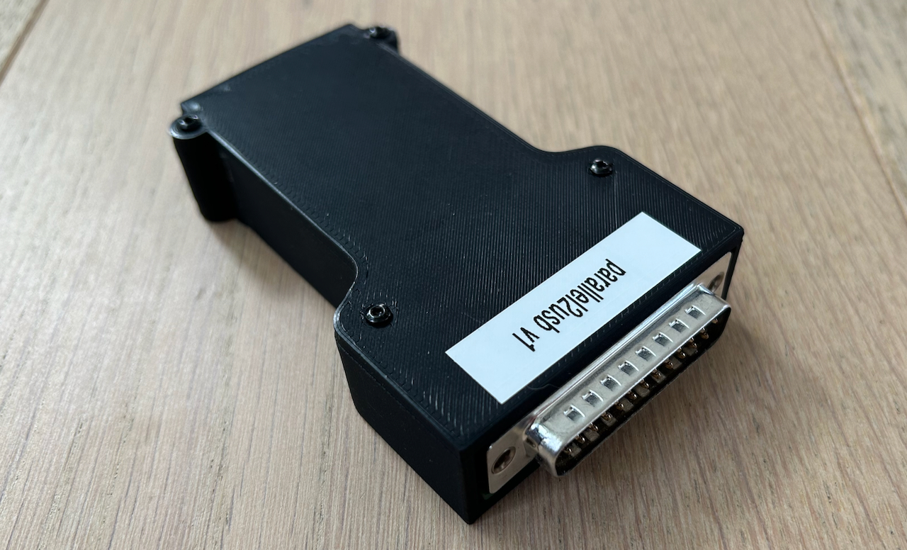
The models was designed with Onshape. You can get it here.
References
- fake_parallel_printer repo on GitHub.
-
I only found out about this project after initially publishing this blog post. It is very similar in scope to my design, but uses an FTDI FT245RL parallel to USB serial converter instead of a microcontroller. Unlike my design, the PCB is designed to fit in DB-25 enclosure: