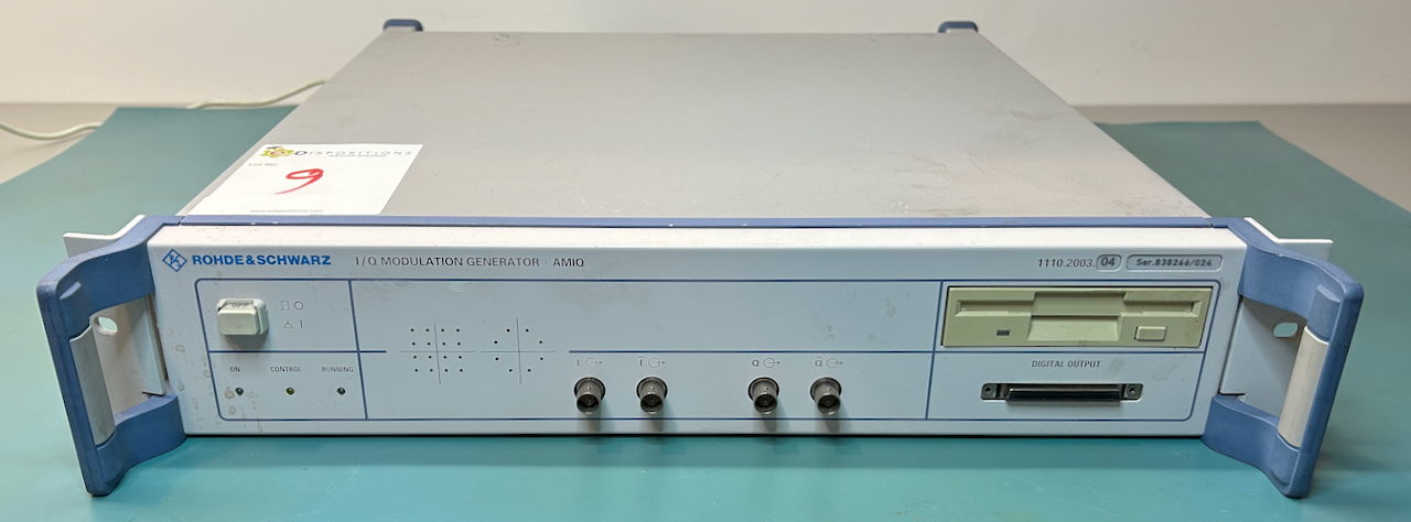
Rohde & Schwarz AMIQ Modulation Generator - Reviving the PC System
- Introduction
- A Late Nineties PC
- Assessing the Damage
- Installing a Video Card and Keyboard
- Locked CPU Fan
- Replace the BIOS Backup Battery
- Replacing the Motherboard Capacitors
- Replacing the Spinning Disk Hard Drive with a CompactFlash Drive
- Digital Configuration Architecture of the Signal Generation Board
- Installing Firmware - The Official Way
- Installation Alternative 1: Floppy Drive Emulator
- Installation Alternative 2: Installed Drive Image
- Controlling the AMIQ with a PC
- The AMIQ and a Rohde & Schwarz SFQ as RF Vector Signal Generator
- References
- Footnotes
Introduction
My Rohde & Schwarz AMIQ teardown and Breaking R&S AMIQ License Keys blog posts featured a working unit, but that wasn’t the case when I first received it. On the contrary, many hours were spent getting it up and running.
There were 2 major issues:
- all the electrolytic capacitors of the PC motherboard had to be replaced
- the hard drive was toast, and with it all the software to make the unit run
In this blog post, I describe how to bring the PC subsystem back to life and make the instrument usable again.
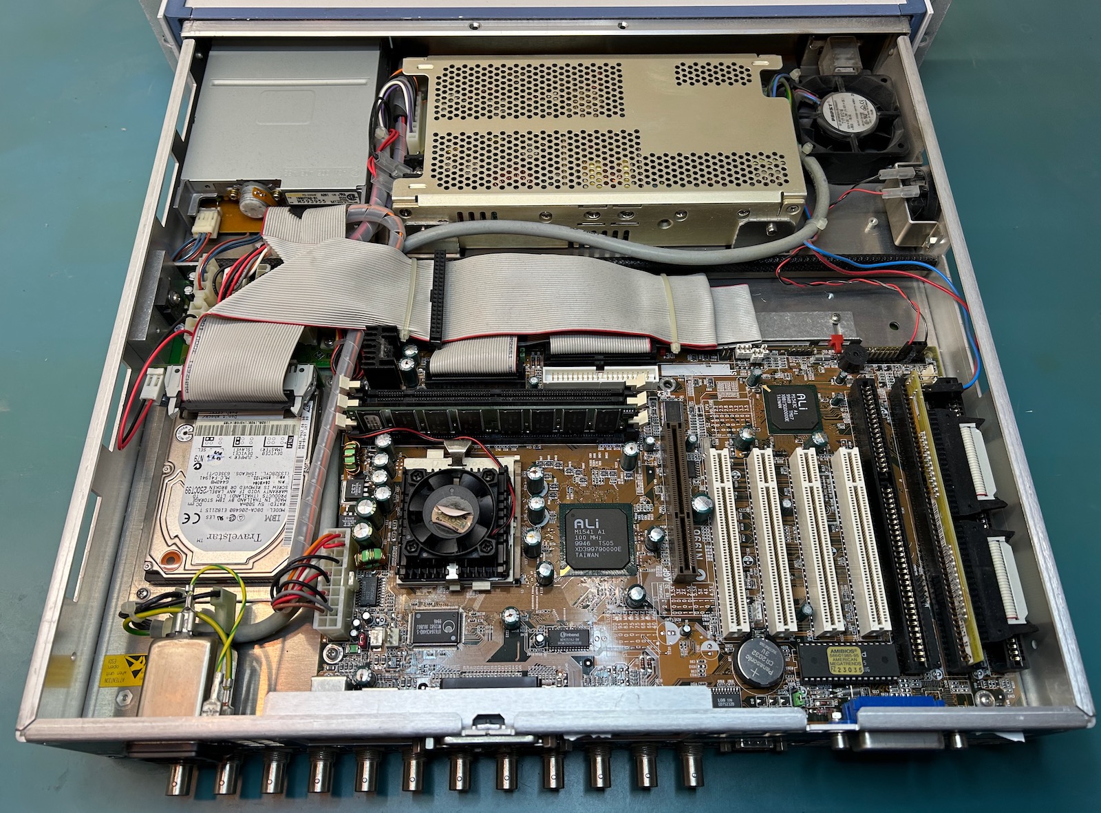
A Late Nineties PC
Much like my Agilent 54831 oscilloscope, the top side of the AMIQ contains a regular turn-of-the-century PC: motherboard, power supply, hard drive, floppy drive and something that’s plugged in an ISA slot.
 (Click to enlarge)
-
MSI MS-5169 motherboard
You can find the details at The Retro Web, but it’s a standard late nineties affair with support for a large selection of socket 7 CPUs from Intel, AMD and Winchip. It’s compatible with SDR UDIMM RAM and 72-pin EDO RAM and it has 4 PCI, 1 AGP, 2 16-bit ISA slots, a floppy and IDE interface and the usual assortment of smaller interfaces for mouse, keyboard, serial port etc.
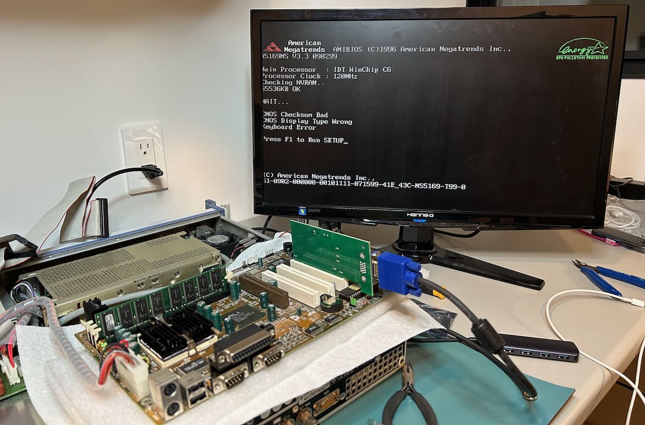
My motherboard came with an IDT WinChip C6 CPU and a whopping 64MB of SDRAM. The CPU is rated at 200 MHz, but the boot screen reports a 120 MHz processor clock. I haven’t yet tried to increase the clock to 200 MHz.
-
IBM TravelStar hard drive
This drive has a capacity of 6.4GB of which only ~2GB is used for the AMIQ. It’s equipped with a parallel IDE interface. This type of hard drive has a reputation of failing read/write heads, which is probably what happened with mine.
- 3 1/2” floppy drive
- Power supply
At the bottom right of the image, we can see a board with 2 flat cables that’s plugged into the one of the 2 16-bit ISA slots. This is the interface that connects the PC system with the signal generation board.
Assessing the Damage
The PC system on my AMIQ was in bad shape. It had the following issues:
- bulging electrolytic capacitors with rust spots on top
- locked-up CPU fan
- broken hard drive
- barely working floppy drive
- empty CR2032 battery
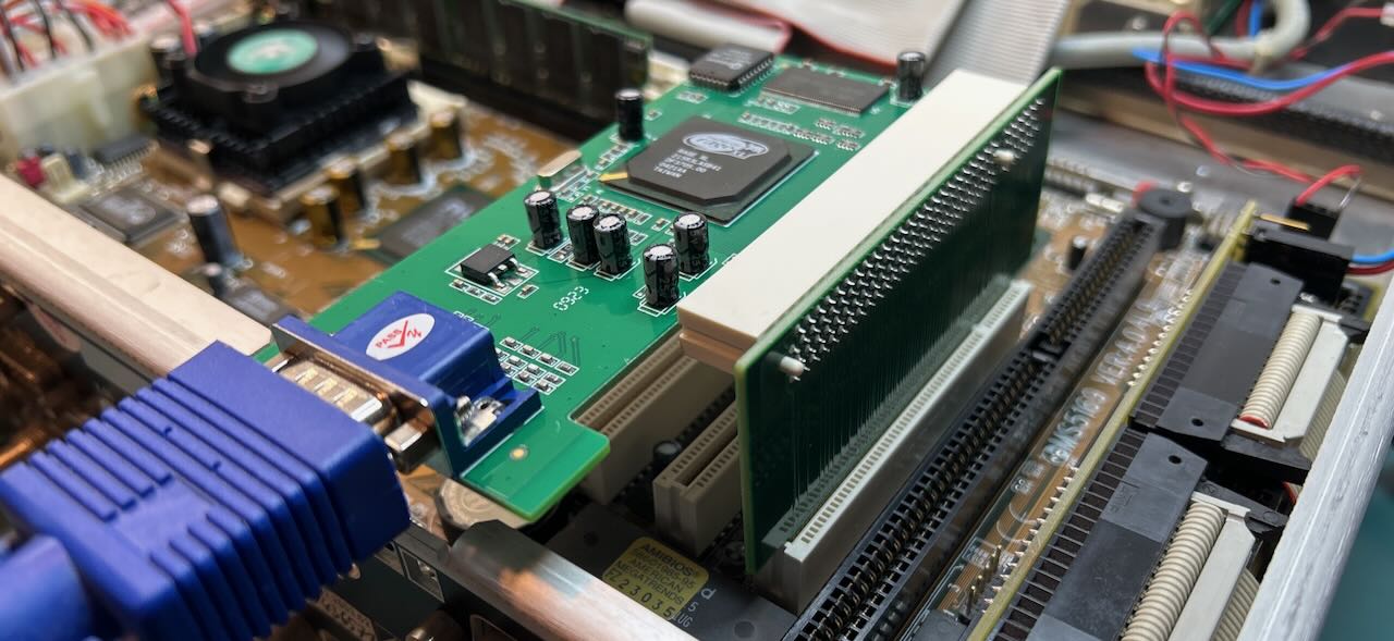
Installing a Video Card and Keyboard
If you want to do any restoration work on the AMIQ, you need to operate it like a PC, with a PS/21 keyboard and a display connected. I found a Korean keyboard on Craigslist for $20. An ATI (meh) Rage XL PCI with VGA output from eBay set me back another $20. I think pretty much any video card with PCI should work as long as it’s not some power hungry monster.
Forget about just plugging in the VGA card in the PCI slot because the AMIQ case is in the way. To make it work, I had to unscrew the motherboard, remove the interface board to the signal generation PCB, and awkwardly float the motherboard with some ESD insulation foam underneath to prevent a short-circuit. A temporary solution at best.
You are not supposed to power up a device with bad electrolytics and a broken fan, but I did it anyway. This was the first sign of life:
 (Click to enlarge)
For $3, I bought this PCI riser adapter from mini-box.com to make the video card fit when the motherboard is mounted in the case.
 (Click to enlarge)
Much better!
You’ll need this kind of solution if you want to plug in the video card and the ISA plug-in card that connects the motherboard to the signal generation board: the flat cables to that board are too short otherwise.
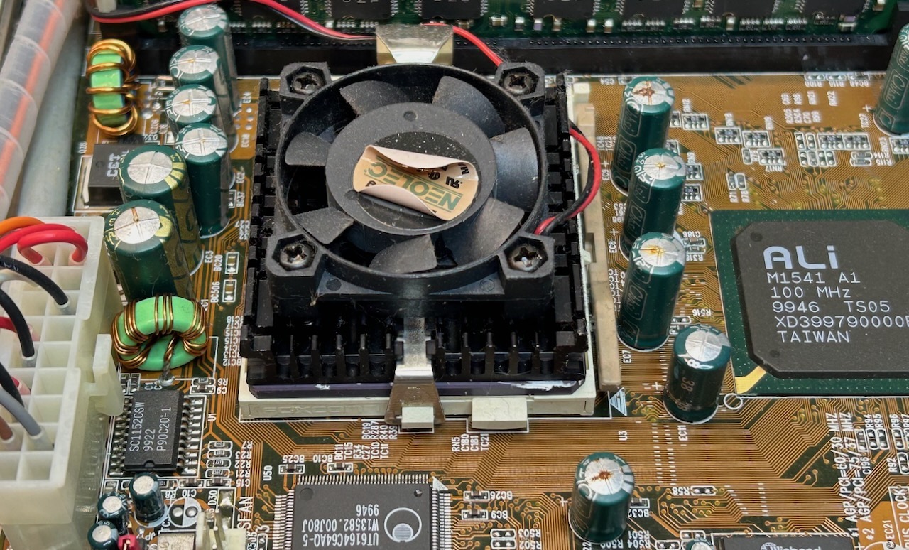
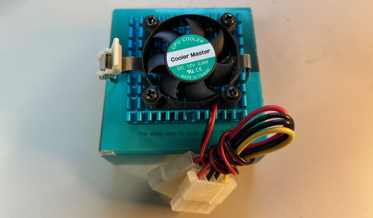
Locked CPU Fan
The CPU fan was locked solid. I don’t know how that happens? I replaced it with a socket 7 cooler from Cooler Master, another $20 spent on eBay. The new fan comes with a heatsink, but I didn’t have any thermal paste on hand, so instead of replacing the full assembly, I unscrewed the fan from the heatsink and installed just that. (I should apply new thermal paste at some point…)
Replace the BIOS Backup Battery
Without this battery, the BIOS won’t retain its settings. Expect this battery, a run-of-the-mill CR2032 to be empty.
Replacing the Motherboard Capacitors
The motherboard was produced in the late nineties and early 2000s, right around the time of the electrolytic capacitor disaster that hit pretty much all PC electronics back then and this one is no exception.
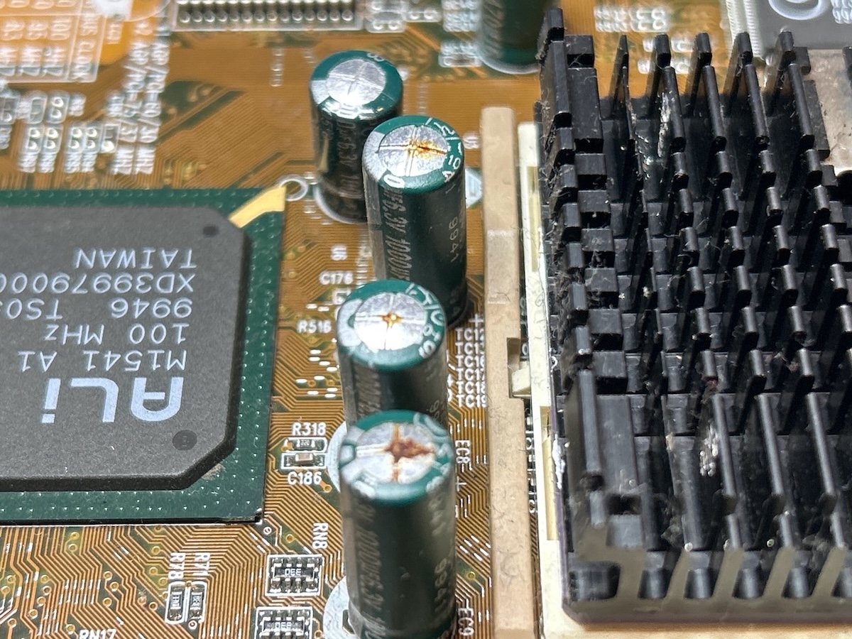
There are 33 electrolytic radial caps on the motherboard and while it’s not possible to visually determine if the smaller ones have issues, all the larger ones had traces of corrosion at the top. There weren’t any signs of leaks, which is great because the fluid inside a cap is corrosive and will eat away the hairline PCB traces.
To give an idea how bad the capacitor situation was, I measured 2.5uF on a 1500uF capacitor. It’s a miracle that the motherboard was able to boot at all.
Here’s the full list:
| Quantity | Capacity | Voltage | Diameter | Spacing |
|---|---|---|---|---|
| 2 | 1500uF | 10V | 10mm | 5mm |
| 10 | 1000uF | 6.3V | 8mm | 3.5mm |
| 5 | 470uF | 16V | 8mm | 3.5mm |
| 7 | 100uF | 16V | 5mm | 2mm |
| 2 | 47uF | 25V | 5mm | 2mm |
| 7 | 10uF | 25V | 4mm | 1.5mm |
You can use my Mouser shopping list if you want, but you do so at your own risk:
-
Not all new capacitors have a low equivalent series resistance (ESR).
Low ESR is important for capacitors that are part of switching voltage regulators because they tend to be exposed to high currents which, in combination with resistance, results in higher power consumption and thus lower power efficiency. It also reduces the lifetime of the capacitor.
I didn’t know for which AMIQ capacitors a low ESR mattered so I winged it. In the list above, the 1500uF, 1000uF and 470uF ones have a low ESR. The others don’t.
-
The quantities in the shopping list don’t match those of the table above. That’s because I ordered one or two spares in case I screwed up. The smaller caps are cheap and harder to handle. In hindsight, I should have bought even a few more spares.
-
The voltages don’t always match: the ones in the shopping list are sometimes higher than the original because the ones with the original voltage weren’t available. That’s fine, don’t worry about it.
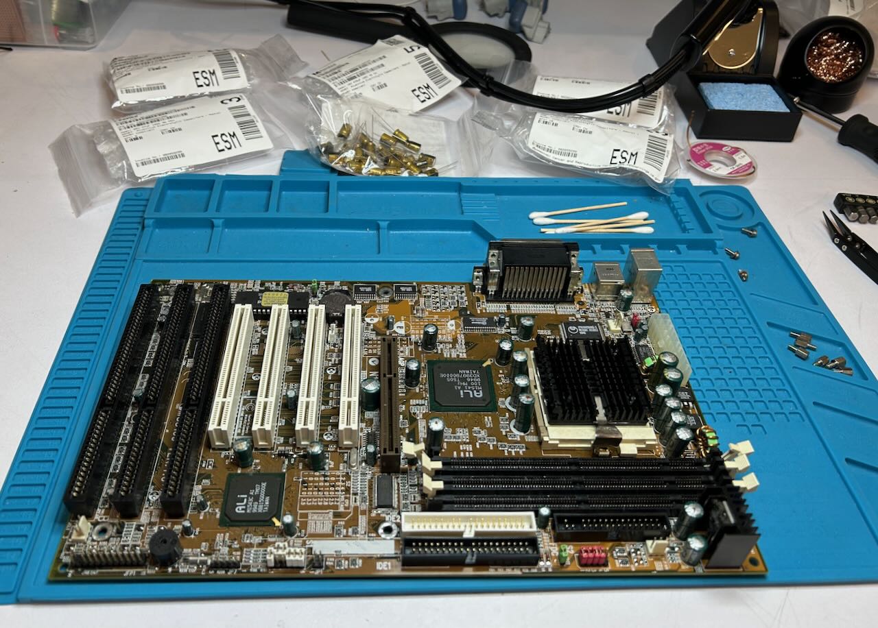
I replaced all of the capacitors. If I had to do it again, I’d probably test one of the small 10uF capacitors and check they were still fine. Some of them are hard to access, squeezed between connectors.
 (Click to enlarge)
Since this was my first recapping job, I watched a bunch of Youtube videos to see how it’s done. I won’t go into all the details here, but here are some notes:
- Pay attention to the polarity of the capacitors that you remove.
- Use a soldering iron temperature that is higher than 350C. The motherboard has a lot of layers that will make the applied heat dissipate away.
- If you’re using a manual desoldering pump like the excellent Engineer SS-03 Solder Sucker, make sure to place it against the pin that’s being desoldered at an angle of around 45 degrees. I held it almost perpendicular to the motherboard on top and, somewhat counter-intuitively, that reduces the sucking power of the pump by a lot.
- Add some fresh solder first. It makes a big difference. Ideally, use low temperature solder for that.
- Make use of gravity. For some of the smaller capacitors, the easiest was to put the PCB upside down (capacitors at the bottom), heat up the pins and watch the capacitor fall out.
- Immediately replace a removed capacitor with a new one, instead of first removing all of them. That reduces the chances of mistakes.
Late nineties motherboards already had many layers and small traces. A lot could have gone wrong, but after the recap the motherboard miraculously powered up without any issues.
Replacing the Spinning Disk Hard Drive with a CompactFlash Drive
At boot, the hard drive made a gnarly clicking sound and while the BIOS was able to detect the drive, it couldn’t read from it. Late nineties IBM TravelStar drives may not be as notorious as their DeskStar brethren for being total pieces of shit, but they have a reputation of failing just the same.
If you’re lucky and the drive still works, you’re living on borrowed time and should still get rid of it.
I replaced mine with a 16GB CompactFlash drive that I had laying around and an $8 2.5” 44-pin IDE to CompactFlash adapter.
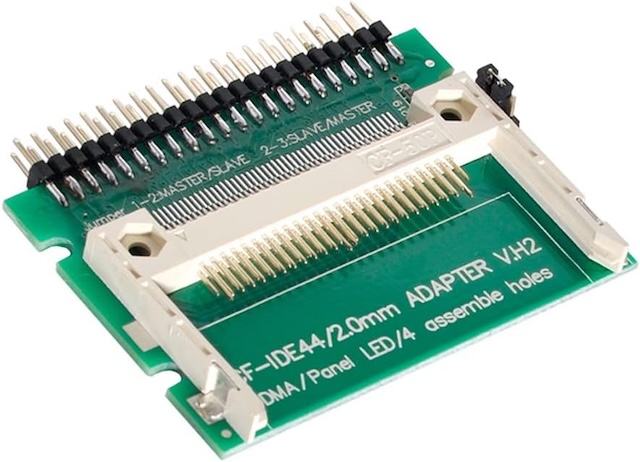
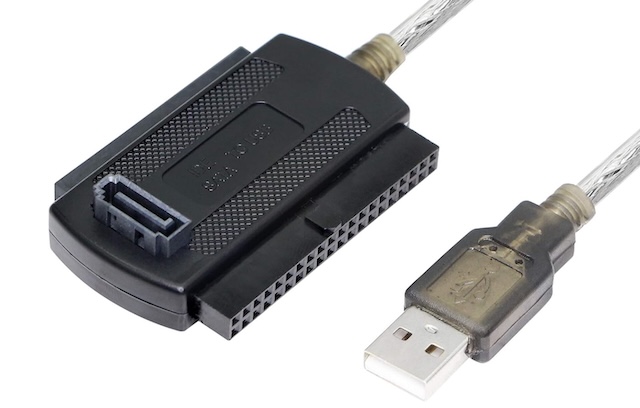
Once removed, I tried to extract the data on the HD one more time with a $10 USB-to-SATA/IDE adapter, but that didn’t work either. When these drives fail, it’s usually because their heads get stuck in their protected-against-vibration idle position. There isn’t much software can do about that…
Digital Configuration Architecture of the Signal Generation Board
When trying to get the firmware to work, I found it useful to understand how the signal generation PCB interacts with the motherboard. And for that, you need to know how various FPGAs and CPLDs are interconnected.

There are 3 programmable logic chips on the PCB:
-
Sequencer FPGA
This Altera EPF10K10 Flex10 FPGA, found on sheet 7 of the schematics, is responsible for general PCB management. Like all FPGAs, its bitstream is volatile so a new configuration is required after each power-up. Unlike most FPGA boards, there is no bitstream configuration flash on the PCB: the FPGA is set to passive parallel asynchronous configuration mode and the bitstream is loaded by the PC over the ISA bus each time.
-
BER FPGA
Another Altera EPF10K10 Flex10 FPGA, located on sheet 28 of the schematic. This FPGA is primarily responsible for the bit error rate (BER) external interface. This feature is only supported when option AMIQ-B1 is enabled, but the FPGA is always there. In fact, even with the BER option disabled, the FPGA is still responsible for driving the JTAG interface to configure the controller CPLD.
Like the sequencer FPGA, this one is also configured at bootup over the PC ISA bus.
-
Controller CPLD
This chip, an Altera EPM7128 CPLD, primarily drives the SDRAM pins, so it’s a good guess that the full name is SDRAM controller. CPLDs tend to have much less logic resources but back when they were popular, they were faster than FPGAs.
CPLDs retain their configuration after losing power so they only need to be programmed once. The controller CPLD is programmed during initial device setup or recovery. It’s not reprogrammed after each power up.
Programming happens over the JTAG pins that are driven by the BER FPGA, which is in turn controlled by the ISA bus.
Installing Firmware - The Official Way
If you start with a blank hard drive, the official way to set up the machine is with the Rohde & Schwarz
PREPARE and PROGRAM disk. The AMIQ has been end-of-lifed a long time ago and you can’t officially get
them anymore, but I was able to find a copy for AMIQ software release 4.00. Not the latest one, there’s at
least a 4.01 version out there, but good enough to get you going.
The original archive with the installation files and instructions is here:
The PREPARE disk contains a minimal operating system and various hardware related files, but
not the main AMIQ application. The PROGRAM disk contains additional utilities and the main
application.
Assuming your AMIQ has a working floppy drive (spoiler: it almost certainly won’t), the installation goes as follows:
- Insert the
PREPAREdisk. -
Have the PC boot up from floppy.
If the AMIQ still has the recommended settings for normal use, booting from floppy will be disabled. You’ll need to go to the BIOS menu to enable it.
The installation system uses a bunch of DOS .BAT files. That makes is relatively easy
to figure out what’s going on.
After booting, the system goes through a bunch of steps:
-
Format the new disk with FDISK.
The maximum partition size is 2GB, but you have the option to add multiple partitions and thus multiple drive letters. WinIQSim, the Windows control software can deal with that when uploading waveforms: just specify the right drive letter.
-
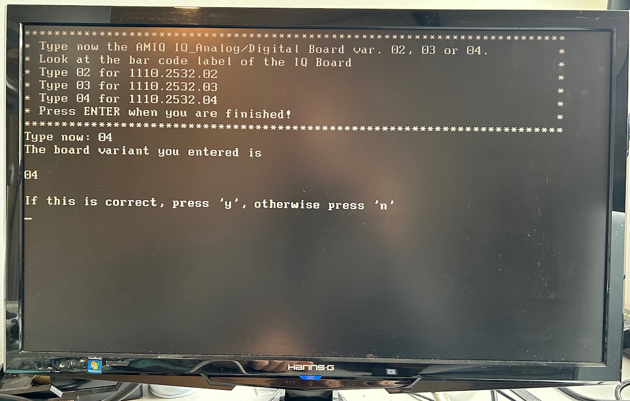
Enter a bunch AMIQ model information:
-
Desired AMIQ Model: 02, 03 or 04
Mine is an AMIQ04 model.
-
AMIQ IQ_Analog/Digital Board variant 02, 03, or 04
There are 3 options, 02/03/04 which you’d think match the model number, but apparently not… otherwise they wouldn’t ask again? I guessed 04 for mine and that worked.
-
Serial number
This will normally be printed on the front panel of the device. Chances are that it doesn’t matter what you fill in here: if the EEPROM on the signal generation board has already been programmed with a serial number, it won’t be overwritten by this step.
-
-
Copy over files from the floppy to the hard drive
-
Reboot machine, change BIOS settings to boot from hard drive
-
Insert
PROGRAMdisk -
Reboot again
-
When a floppy with an
AMIQ.DATfile is found on the floppy drive, the system will automatically copy all its contents and overwrite the existing software installation. TheAMIQ.DATfile is nothing but a ZIP archive that has been given a different filename extension.
Done!
Installation Alternative 1: Floppy Drive Emulator
I have a lot of old test equipment with floppy drives, literally none of them working reliably enough for practical use. My AMIQ was no different. I still wanted to get a clean installation the way R&S intended it to be, so I spent another $30 for a GoTEK 3.5 Floppy Drive Emulator.
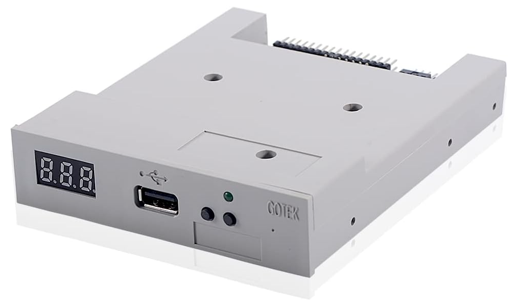
Permanently replacing the old AMIQ floppy drive with a new one is not for the faint of heart: you need to take pretty much the whole unit apart. I didn’t bother, and just connected the emulator temporarily, with the case open:
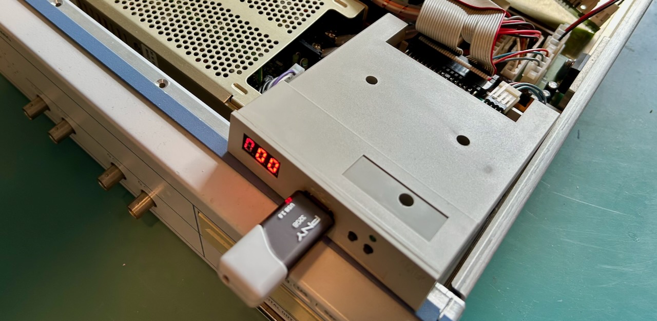
The emulator works as follows:
-
With the USB Floppy Emulator software, write up to 100 different 1.44MB floppy disk images to a USB drive.
- Insert the USB stick in the emulator hardware
- Select the desired image number with the buttons of the front panel
That’s it! The software is clunky, but it works.
USB floppy manager expects disk images in .img format. You can download them here:
They’ve been compressed with gzip.
Even if you want to use a real floppy drive, these images are still useful to prepare the 2 floppies.
Installation Alternative 2: Installed Drive Image
I used this method before I got my hands on the official installation disks. It took ages to make it work.
If you don’t want to go through the whole floppy drive (emulator) business, you can just copy an AMIQ hard drive image backup straight to the new drive. This is definitely the easiest option… if it works. The problem is that a drive image is created for a given hardware configuration.
Here’s a look at the \AMIQ directory of a working disk image:
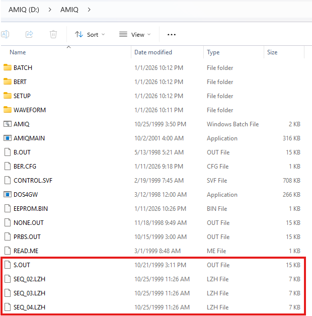
You can see 3 SEQ_*.LHZ files: there are compressed bitstream images for AMIQ
sequencer FPGA. During the floppy drive installation, one of them was decompressed
as S.OUT, depending on the AMIQ model number. This is the bitstream that gets
uploaded after power up. If you want to patch a disk image to make it work with a
different sequencer bitstream, you’ll have to replace S.OUT with one of the
decompressed other SEQ_*.LHZ files.
The PREPARE disk also contains 3 CONT_*.LHZ files on the PREPARE disk, but
you won’t find them on the disk image: that’s because the contents of these files
are flashed to the CPLD one time during the PREPARE installation step. They don’t
need to be reflashed again after each power-up. You only need to worry about this
if our device was running a very old firmware version. If that’s the case, here
the \AMIQ directory of the PREPARE disk:
tom@zen:/media/tom/14E4-1358/AMIQ$ ll
total 166
drwxr-xr-x 2 tom tom   512 Apr 29  1999 ./
drwxr-xr-x 5 tom tom  7168 Dec 31  1969 ../
-rwxr-xr-x 1 tom tom 11942 Mar  2  1999 AMIQINIT.EXE*
-rw-r--r-- 1 tom tom  2352 Jun  1  1999 B.LZH
-rw-r--r-- 1 tom tom 15757 Jun  1  1999 CONT_02.LZH
-rw-r--r-- 1 tom tom 15724 Jun  1  1999 CONT_03.LZH
-rw-r--r-- 1 tom tom 16623 Jun  1  1999 CONT_04.LZH
-rwxr-xr-x 1 tom tom 76900 Jan 24  1999 LOADCON.EXE*
-rw-r--r-- 1 tom tom  6886 Oct 25  1999 SEQ_02.LZH
-rw-r--r-- 1 tom tom  6886 Oct 25  1999 SEQ_03.LZH
-rw-r--r-- 1 tom tom  6984 Oct 25  1999 SEQ_04.LZH
LZH is a file compression format that was popular in the nineties.
-
CONT_*.LZHare compressed SVF files for the control CPLD. There are 3 AMIQ versions, 02, 03 and 04, each with a unique file. During installation, one of these files is uncompressed into aCON_*.SVFfile, renamed toCONTROLS.SVF, and programmed the CPLD with theLOADCON.EXEutility. -
Like the control CPLD, there are 3 bitstreams
SEQ_*.LZHfor the sequencer FPGA. One of the files gets uncompressed and renamed toS.OUT. There is only 1 bitstream version of the BER FPGA:B.LZH. It gets decompressed and renamed toB.OUT.AMIQINIT.EXEis used to send theS.OUTandB.OUTbitstreams to the FPGAs during each boot cycle.
You may see this error on your AMIQ-connected VGA monitor:
Error: 243, “AMIQ variant check failed;Board-ID 155: Bit:24/24 Version:05/06”
This is guaranteed to be a case of using the wrong SEQ bitstream or CONTROL configuration file.
Controlling the AMIQ with a PC
When everything installed correctly, you should be able to control the AMIQ with a PC through the WinIQSim software, using either an RS-232 or GPIB cable… in theory.
In practice, it will often just not work: with RS-232, I was able to make a reliable connection, but it’s slow and uploading a waveform often ends with a transmission error. GPIB initially didn’t work at all: I could send commands with software other than WinIQSim, but WinIQSim itself refused to even initiate a connection. Others have seen this as well, and have gone as far as building a PC just for this purpose, with a 20 year old motherboard and running Windows XP.
In my case, that wasn’t necessary: suddenly, after many hours of trying, it did work! But I have no clue what I did to make that happen. I plan to experiment some more, starting with a clean PC, to find a reliable working recipe.
The AMIQ and a Rohde & Schwarz SFQ as RF Vector Signal Generator
Since the AMIQ only generates baseband I/Q signals, you still need an RF vector signal generator to upconvert the signal into the RF space.
The natural companion for the AMIQ is the R&S SMIQ, but those are still pricy. The R&S SFQ TV Test Transmitter is not a bad alternative. While it’s primary purpose is to generate test signals for DVB-T, DVB-H and a bunch of other digital TV standards, the external I/Q inputs go well with the AMIQ. The SFQ datasheet lists a baseband I/Q frequency response of DC to 22.5 MHz (+/-1 dB.) The SMIQ datasheet talks about a vector modulation bandwidth of 30 MHz (+/-3 dB.)
I found one at a liquidator for $200. The SFQ has different options, some of them can be enabled in software with a license key *cough*, but many require a dedicated plug-in card. I assume that all units support external I/Q, but make sure to check, e.g. by looking at the back for external I/Q input BNC connectors.
Here’s the photo of the AMIQ sending a multi-channel signal to SFQ, spectrum analyzer showing the end result:
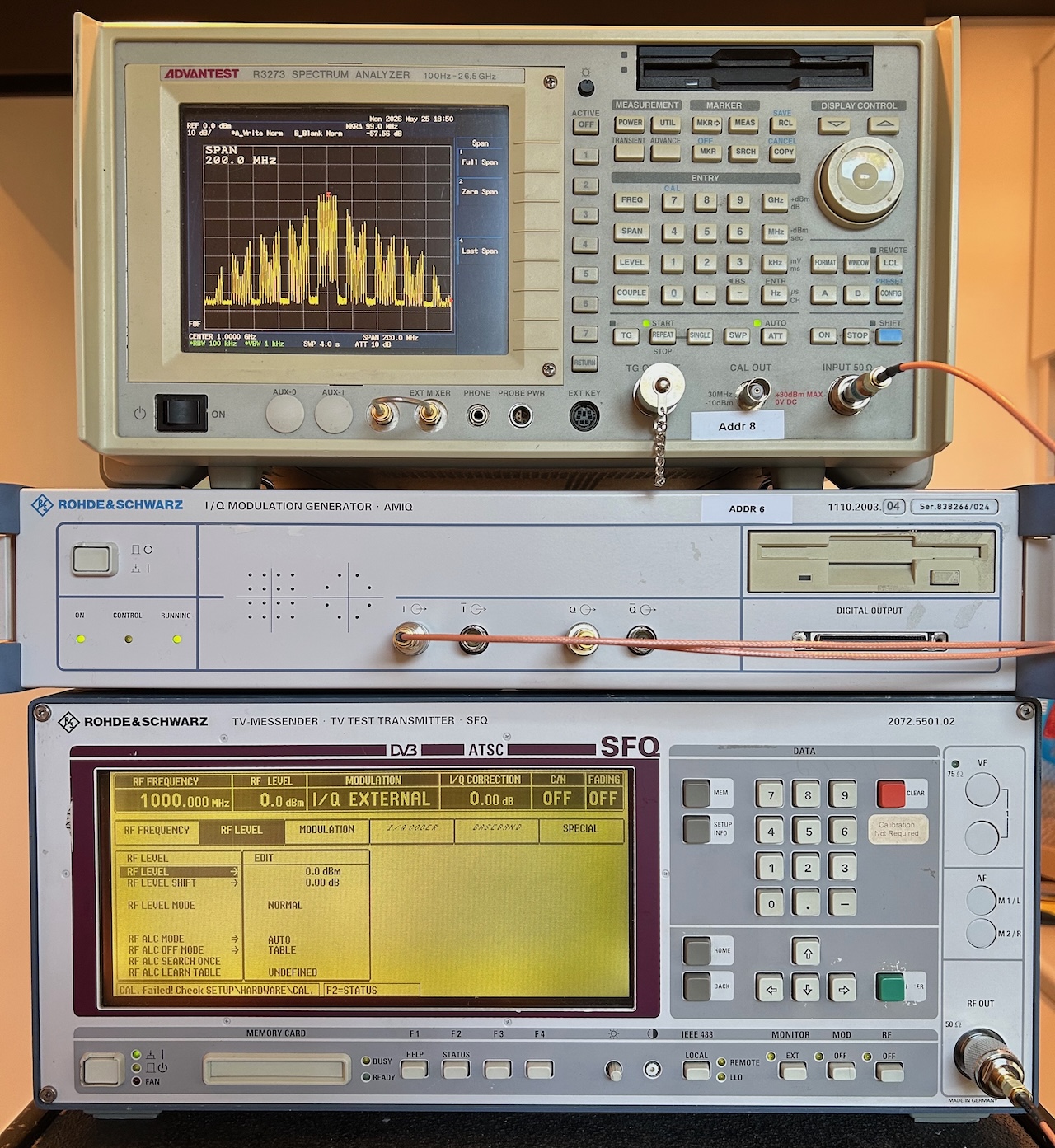 (Click to enlarge)
The spectrum above shows 4 shadows to the left and to the right of the multi-channel frequencies in the center. This is because the post-DAC anti-aliasing low-pass filters were disabled. For best results, one would need a sharp custom external filter after the DACs. I mention this in my AMIQ teardown blog post.
All words in this blog posts were written by a human.
References
-
There are a lot of references at the bottom of that blog post.
Firmware
Recapping
- Choosing Capacitors to Recap Old Electronics
- Six Common Mistakes Made When Recapping Vintage Electronics
Footnotes
-
The motherboard has 2 USB ports, but a USB keyboard didn’t work. I don’t know if that’s a BIOS limitation or one of Caldera OpenDOS that is used as OS. ↩