Repair of 2 Agilent 54831 Oscilloscopes
In the end, it comes down to fixing two early 2000s PCs…
- Introduction
- The Agilent 54831
- Inside the PC System of the 54831
- Unit A: Agilent 54831M
- First Suspect: the IBM TravelStar HD
- Getting the PC to Boot
- Unit B: Agilent 54831B
- A CompactFlash Adapter without Cable
- Installing the Software
- CPU Temperature Alarm
- Upgrade to 1 GHz Bandwidth
- Additional Changes are Possible
- Conclusion
- References
- Footnotes
Introduction
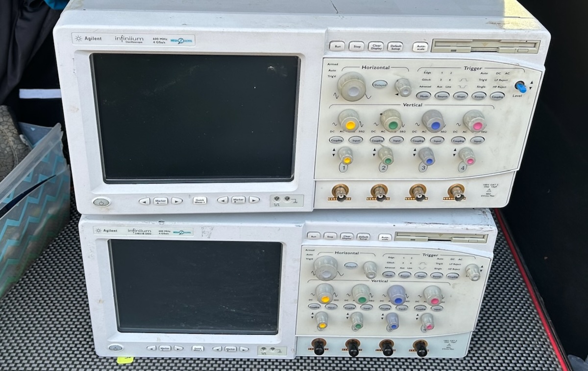
After 6 months of deprivation, a new season of Silicon Valley Electronics Flea markets is upon us! I didn’t make it there at the 6am starting time, even getting there at 6:45am was a struggle, but not a moment too soon because one vendor was selling not one but two broken Agilent1 54831 oscilloscopes, $200 for both of them. While I considered the marital implications of having to defend 2 additional boat anchors in my garage, others were lining up after me, so I made the courageous decision to take the deal.
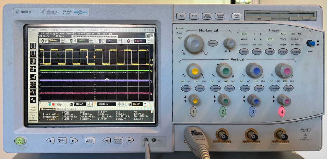
The Agilent 54831
The specs of the 54831 are still pretty decent by today’s hobbyist standards:
- 4 channels
- 600 MHz BW
- 4 Gsps
There are some limitations: channels 1 and 2 and channels 3 and 4 share the same AD converter. To reach 4 Gsps, you can use only either channel 1 or channel 2 but not both, and either channel 3 or channel 4 but not both, otherwise the sample rate drops to 2 Gsps.
The 54832 is the slightly more potent sibling of the 54831 with an analog bandwidth of 1 GHz, but like the Tektronix TDS 754D and the TDS 784D, the 54831 can be upgraded to a 54832 with a single resistor modification.
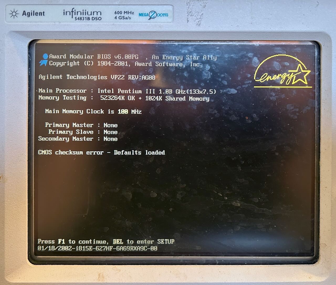
The HP 548xx oscilloscope series was one of the first kind of test equipment that used Windows as their base operating system. I have an older HP 54825A, introduced in 1997, that runs Windows 95. The 54831 was introduced in 2002. Early versions ran on Windows 98 SE Embedded, Agilent later switched to Windows XP.
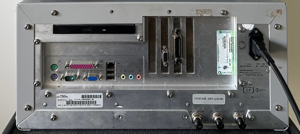
For many years, Agilent used a Motorola VP22 motherboard to manage the test equipment and that’s what mine have as well.
Inside the PC System of the 54831
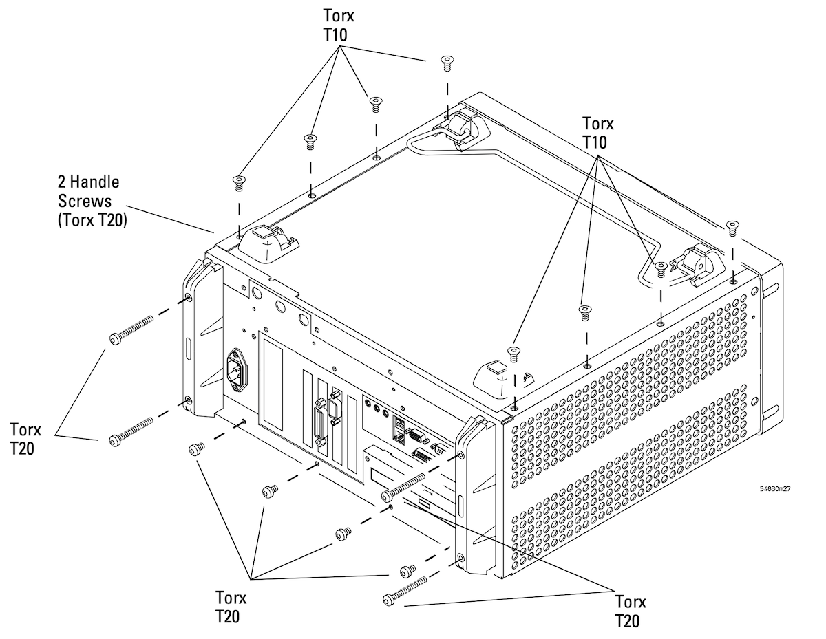
Many pieces of test equipment2 use a sleeve-like enclosure that slides around the inner assembly. I’m not really fond of that: it can be clumsy to remove and put back, even if you only need to work on the top side of the scope, the bottom electronics are exposed as well. The 54831 has separate top and bottom covers. The only disadvantage is that there are much more screws to hold it together: you need to remove 16 of them just for the top cover.
Figure 6-1 of the service guide shows that very well:
 (Click to enlarge)
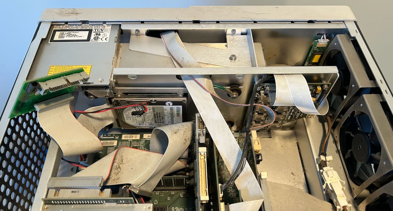
After removing the top cover, you should see something like this:
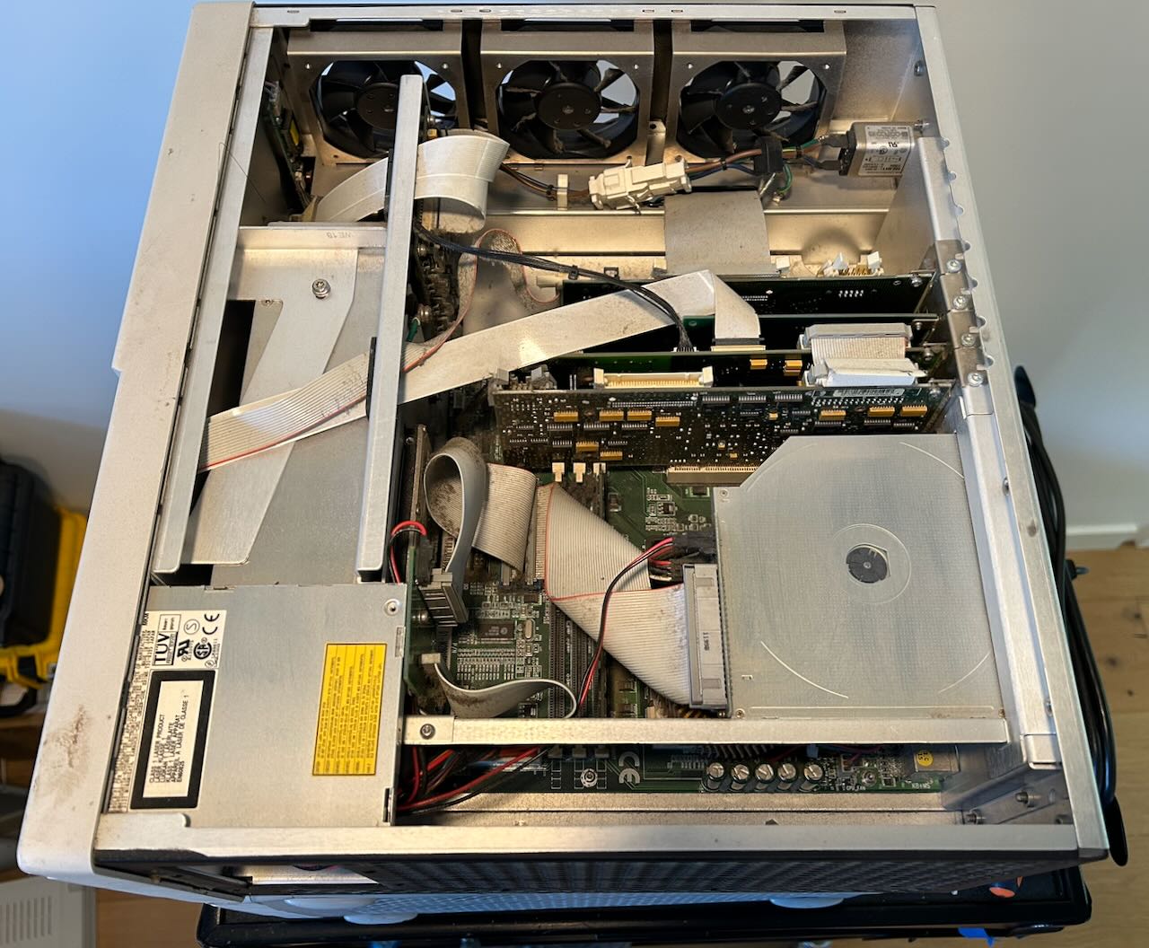
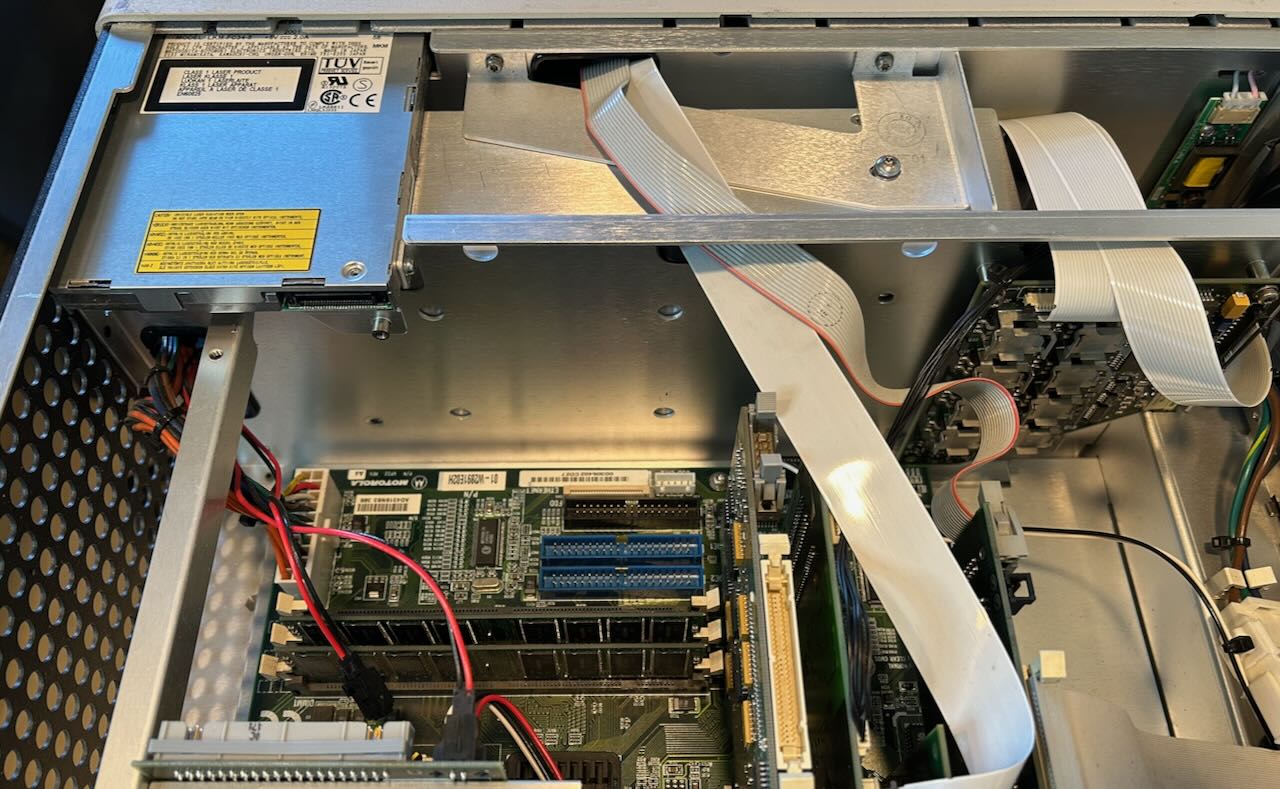
It’s really just a PC with some custom PCI plug-in boards. From top to bottom:
-
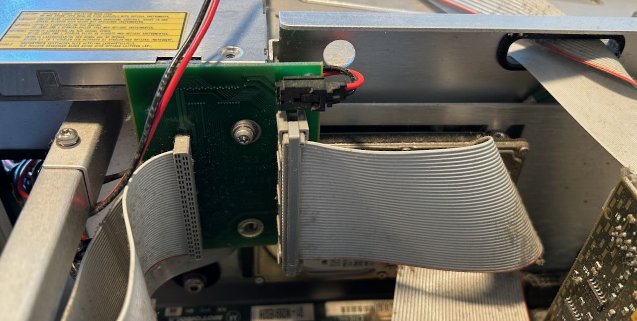
PCI to PCI bridge board
The acquisition board has its own PCI interface. The PCI signals are carried over a wide flat cable that’s terminated on the PC side by a TI PCI2050PDV PCI-to-PCI bridge chip on this board.
I think this is the first time I’ve seen PCI signals being carried over a flat cable.
In addition to the PCI flat cable to the acquisition board, there’s also a narrower flat cable on the side that goes to the front panel.
- GPIB interface board
-
Display adapter
This board, based on a CHIPS F65550, is more than a regular VGA board: it has a flat panel interface to the LCD front panel and an LCD backlight controller. There’s also a bridge cable to the next board that carries the real-time waveform overlay.
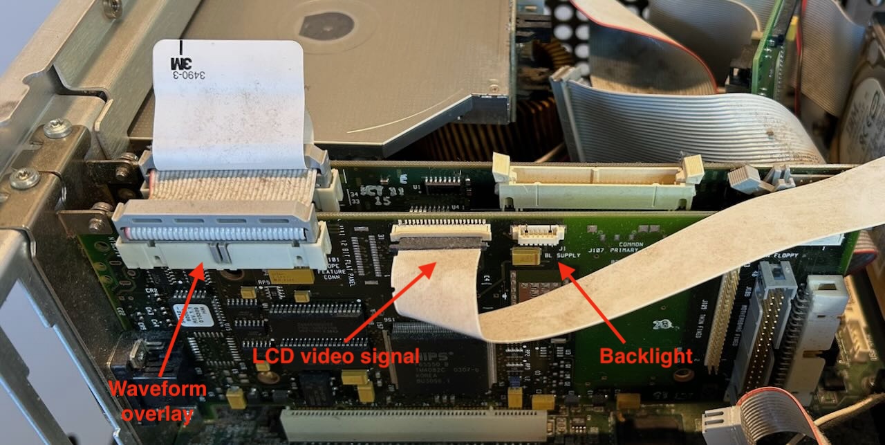
As was the case with some 3D graphics accelerators in the nineties, the VGA card renders the GUI, but waveforms are rendered by a separate card and merged with the GUI in hardware.3
-
Waveform overlay rendering board
The full scope of this board is not 100% clear: based on an Altera FPGA, it definitely renders the video overlay, but I don’t know if it does anything beyond that.
While it has a bunch of connectors, none of them are used in the 54831 except for the bridge cable to the display card. This means that all data is going through the PCI bus.
The other components are standard PC stuff:
- Motorola VP22 motherboard
- Pentium III 1 GHz (SL52R, 370 socket)
- CDROM drive
- Superdisk LS120 floppy drive
- 10 GB IBM TravelStar hard drive
Unit A: Agilent 54831M
The “M” stands for military version. That doesn’t mean it has different specs, it’s just that it has been assembled in Singapore, a country that’s considered more trustworthy than Malaysia, where HP scopes were usually assembled (or so someone claims on The Internet.)
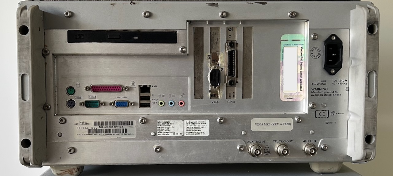
The seller claimed that this unit didn’t work at all, and he was right. When plugging the power cord, it immediately started to squeal long ominous beeps and that was it.
This unit has VIN# M42 (Rev.A.02.30), a production date of October 31, 2003 and according to the Microsoft license sticker it’s one of the early versions that runs Win98.
First Suspect: the IBM TravelStar HD
My Rohde & Schwarz AMIQ came with a non-functional IBM TravelStar HD. They are only slightly less notorious than the IBM Death…DeskStar drives and known to fail with a stuck read/write head assembly, so I assumed that this would be the case here as well.
The first step was to extract the drive, check if it was still working outside of the scope, and create a backup image.
 (Click to enlarge)
HP always puts their spinning disk hard drives on a separate platform that’s mounted on the main chassis with some rubber feet to reduce the chance of damage due to rough handling or vibrations. The screws that fix the drive to the platform aren’t accessible, so you need to remove the platform first, then remove the drive.
Removing the hard drive
I disassembled pretty much the whole PC section of the scope to get to the hard drive:
-
Disconnect all cables
Make sure to first unlock the flex cables before pulling them out!
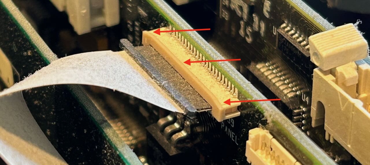
The IDC flat cable connectors have a metal retaining clip around them. Make sure you remove those first before trying to pull the connectors out. It’s easy to do with a screwdriver.
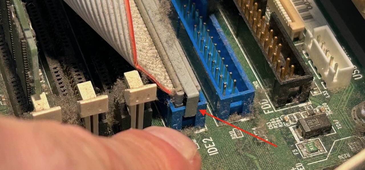
- Remove all the PCI boards
-
Remove adapter board that merges floppy drive and hard drive cables
-
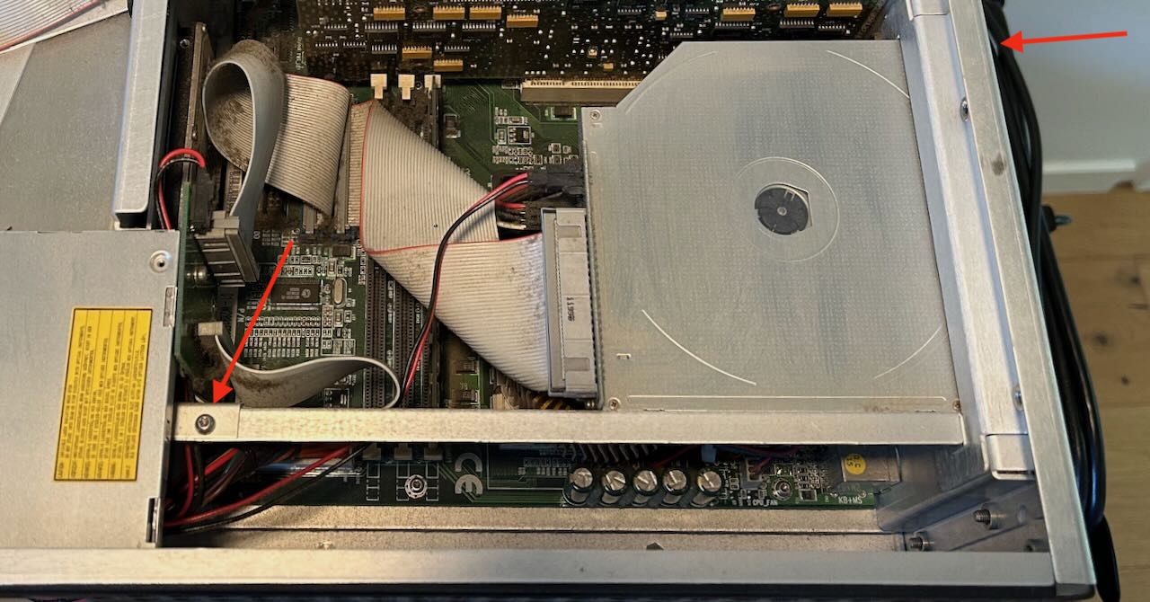
Remove the CDROM drive
This requires removing a screw on the long stick across the case and one screw on the back of the case. See arrows:
 (Click to enlarge)
After this, you can slide the drive back a little bit and lift it out of the case.
-
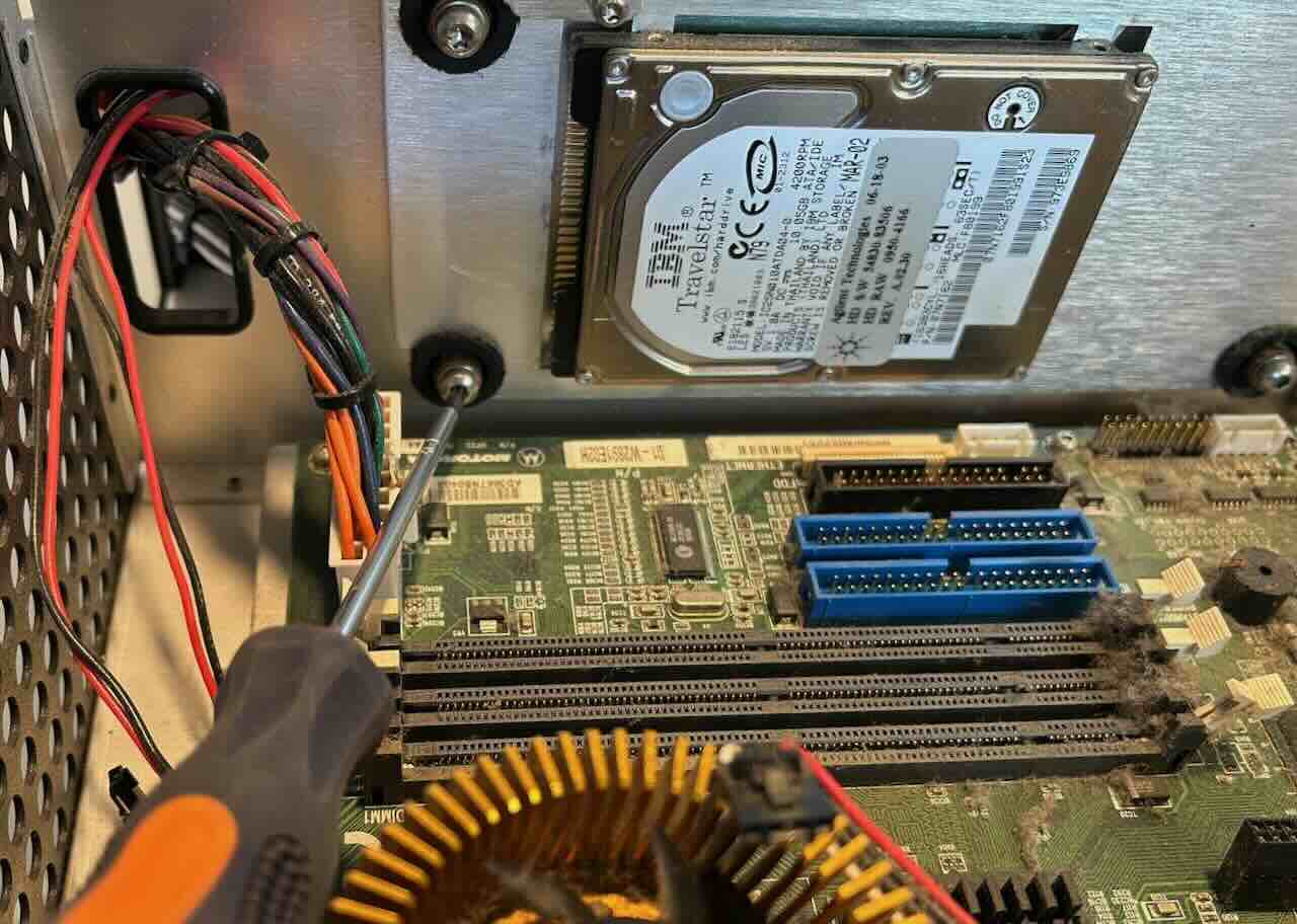
Remove the DRAM stick to access the bottom screw of the hard drive platform
-
Unscrew the hard drive platform
You now have access to all 4 screws of the platform.
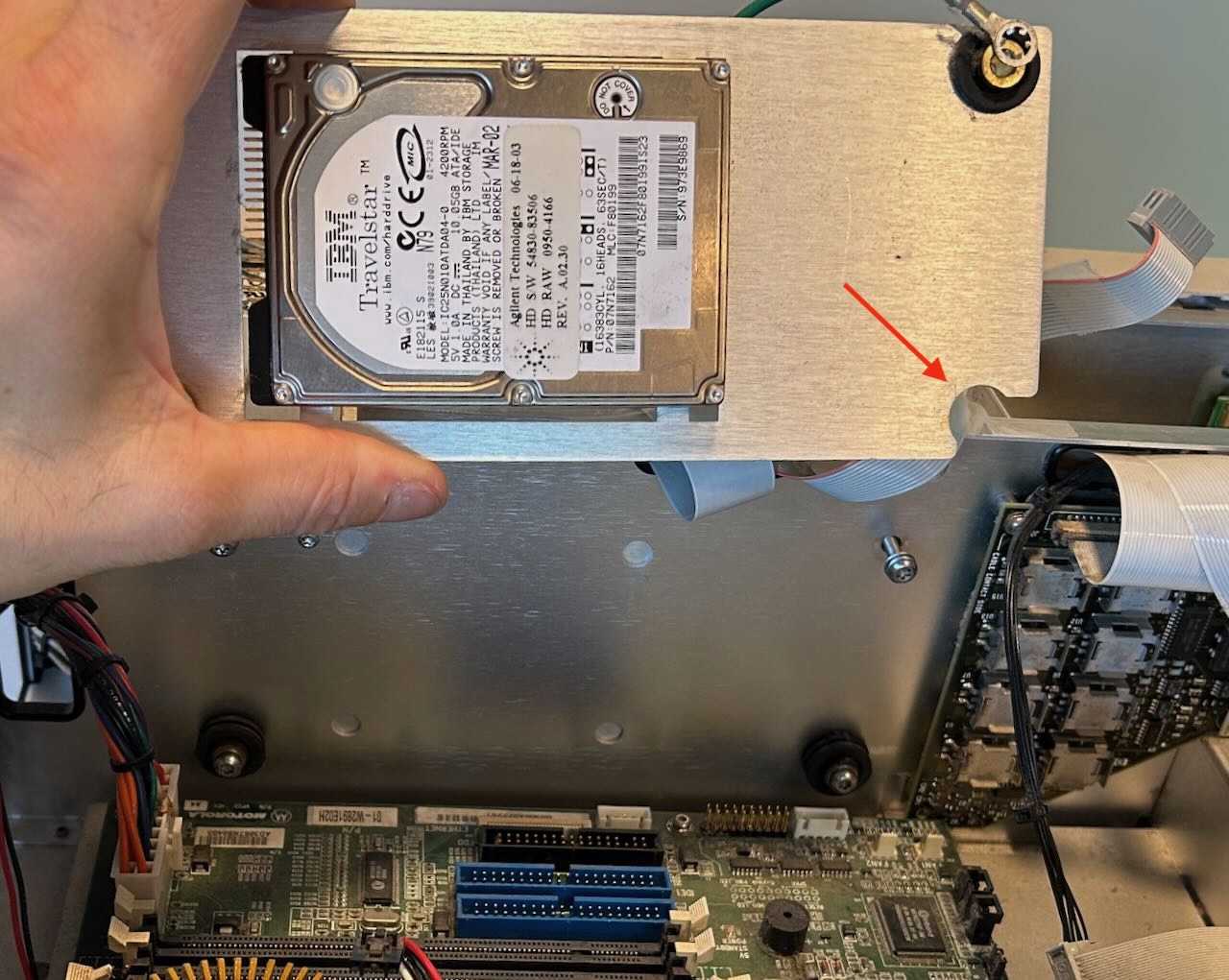
Only after removing the platform by removing all 4 screws did I notice that the bottom 2 rubbers feet were not completely enclosed by the platform. It should be possible to remove the platform with a bit of force, without loosening the bottom 2 of the 4 screws.
The hard drive platform is freed!
Creating a hard drive backup image
I use a cheap USB to SATA IDE adapter cable to connect the drive to a PC, and HDD Raw Copy Tool to create a backup image.
Contrary to my expectations, the TravelStar HD worked fine! I could copy the whole drive without any errors:
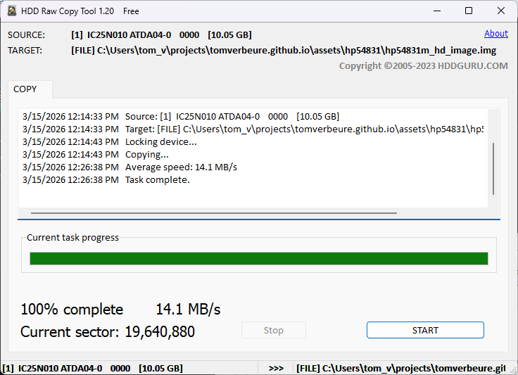
I still expect that this drive will die eventually, but with a backup on hand, I reinstalled the drive back into the scope.
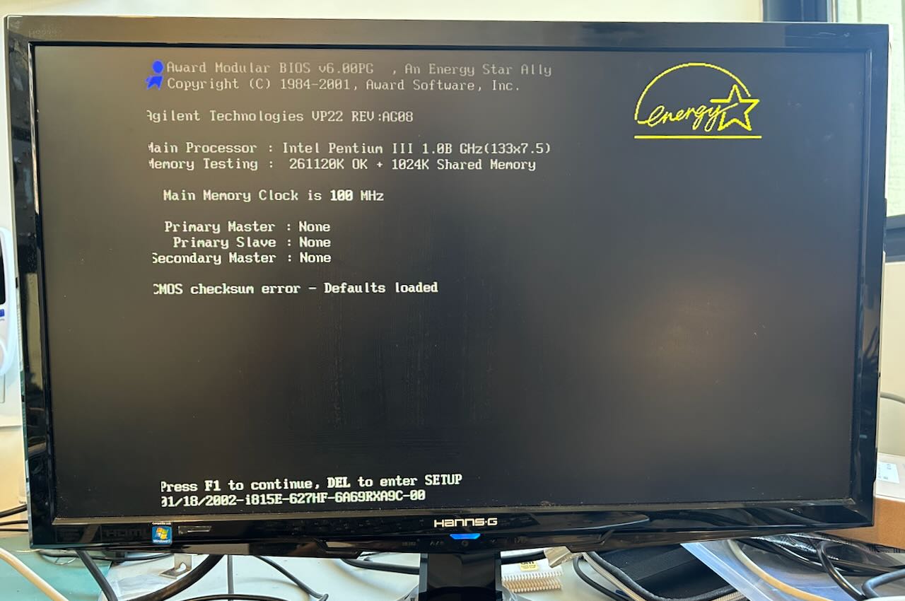
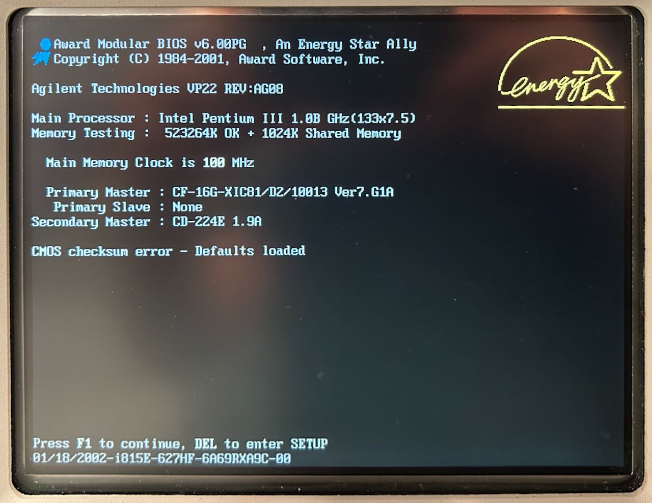
Getting the PC to Boot
The drive was functional, but the scope didn’t boot. I decided to strip the motherboard from all custom cards and make it work as if it were a 23 year old PC with only DRAM and an old PCI VGA card that I had lying around. That didn’t work either.
The error signature was a repeating pattern of a long beep followed by a long pause. It didn’t match any of the standard AMI BIOS error codes.
What if the issue was the CPU itself?
First step is to figure out how to remove the cooler:
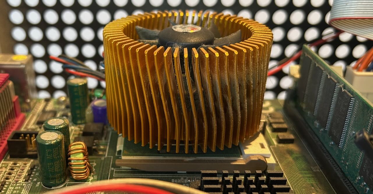
With help from Mastodon, I was able to figure out that the cooler is a Thermaltake Golden Orb Mini. There’s even still a website with a review and installation procedure! And that’s a good thing, because I don’t think I would have figured out that you need to do a clockwise rotation of the cooler to detach it from the CPU.
On a whim, I remove the CPU from the socket, plugged it back in and…
The dumb thing worked! Removing and reinserting the CPU was really all it took.
Another 15 minutes of installing the PCI boards and cables again, and I got to see this:
Success!
Unit B: Agilent 54831B
I immediately started on the second unit. This one a slightly younger B version, made in Malaysia with VIN# M32 (REV.A.03.50), running Windows XP Professional instead.
As told by the seller, this one lights up, but gets stuck at the boot screen. And indeed:
We can see the same 1 GHz Pentium III, the DRAM got an upgrade from 256 to 512 MB, but no drives of any kind are detected. Which made sense once I opened it up:
The BIOS doesn’t detect any drives, because there aren’t any… There are also no IDE cables and the custom board with the specialty LS120 floppy drive connector is missing as well. I can live without floppy drive, I need a hard drive and a CDROM drive is nice to have.
A CompactFlash Adapter without Cable
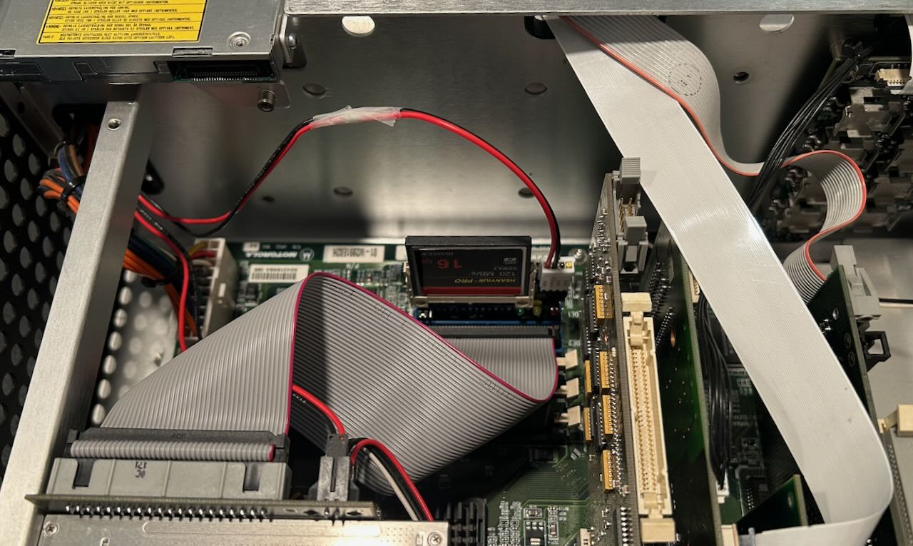
I usually replace spinning disk hard drives with CompactFlash cards. In the past, I’ve used adapter boards that accept a 40-pin IDE cable, but this time I found something better: an adapter board that plugs straight into the PC motherboard:

You can find them here on Amazon, only $8 for 2.
The adapter board requires an external 5V or 3V supply through 4-pin Molex floppy connector. For another $8, I bought 4 of those, again on Amazon.
The scope has a 2-pin connector with 5V and GND, I cut that off and connected it to the Molex connector:
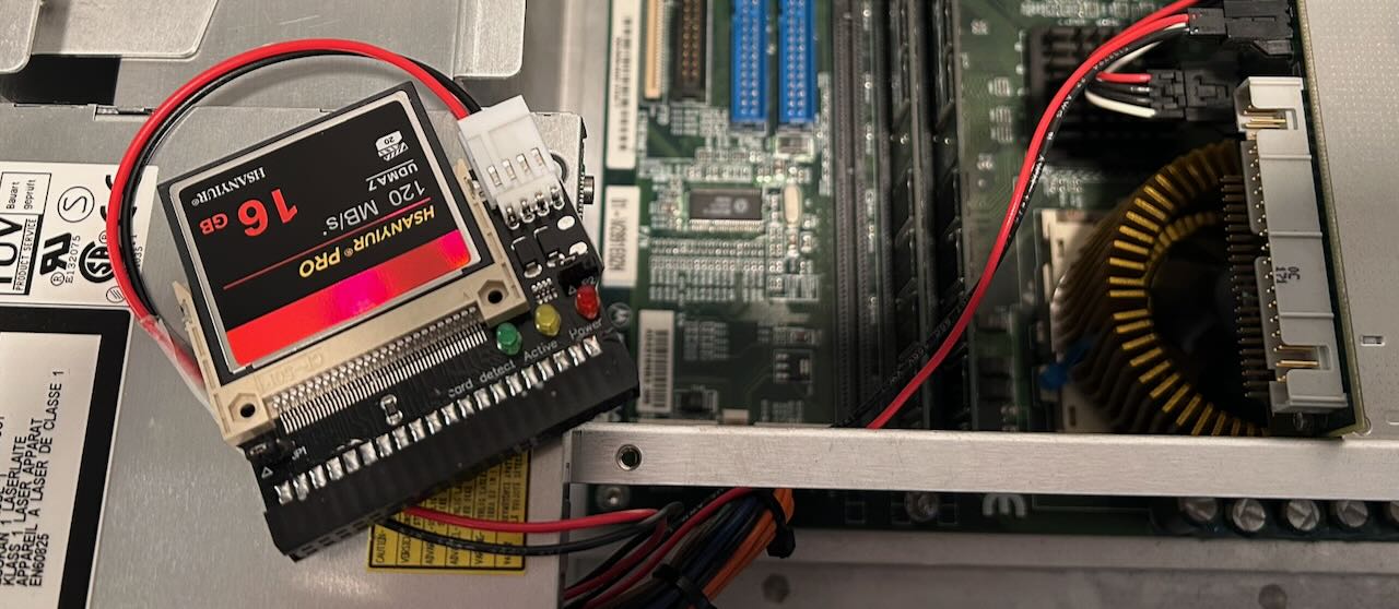
There are 3 LEDs on the adapter with “Detect”, “Active” and “Power” next to them. None of these worked, but when plugged into the motherboard, my 16GB CF card got detected just fine:
Note that the CDROM drive is also detected, because I bought 2 40-pin flat cables for $9. It’s weird that 2 simple cables are more expensive than 2 adapter boards with active components.
Here are the adapter and the CDROM cables installed in the motherboard:
Installing the Software
Important: if your 54831 originally came with Windows 98 SE, a Windows XP image may or may not work. Some scopes with Windows 98 have PCI extension boards that are not compatible with the WinXP drivers.
Next up: finding the software to run the scope. The hard part is not finding the software, this scope is quite popular with hobbyists who are willing to share, it’s to figure which one to use.
I ended up using an image stored on the OneDrive of Tony_G. (Thanks Tony!)
It contains way more than I needed, but the golden ticket was the 6.38 GB xp54831.vhdx file in
the 54831M directory. Also check out Install hints.pdf in the same folder with the installation
instructions.
It all comes down to this:
- Install Rufus, a utility to create bootable USB drives.
- Connect the CompactFlash card to your PC with a CompactFlash to USB adapter like this one on Amazon. I used a 16 GB CF card. I think 8 GB should work too, but I’m not 100% sure.
- Copy over
xp54831.vhdxto the CF card with Rufus.
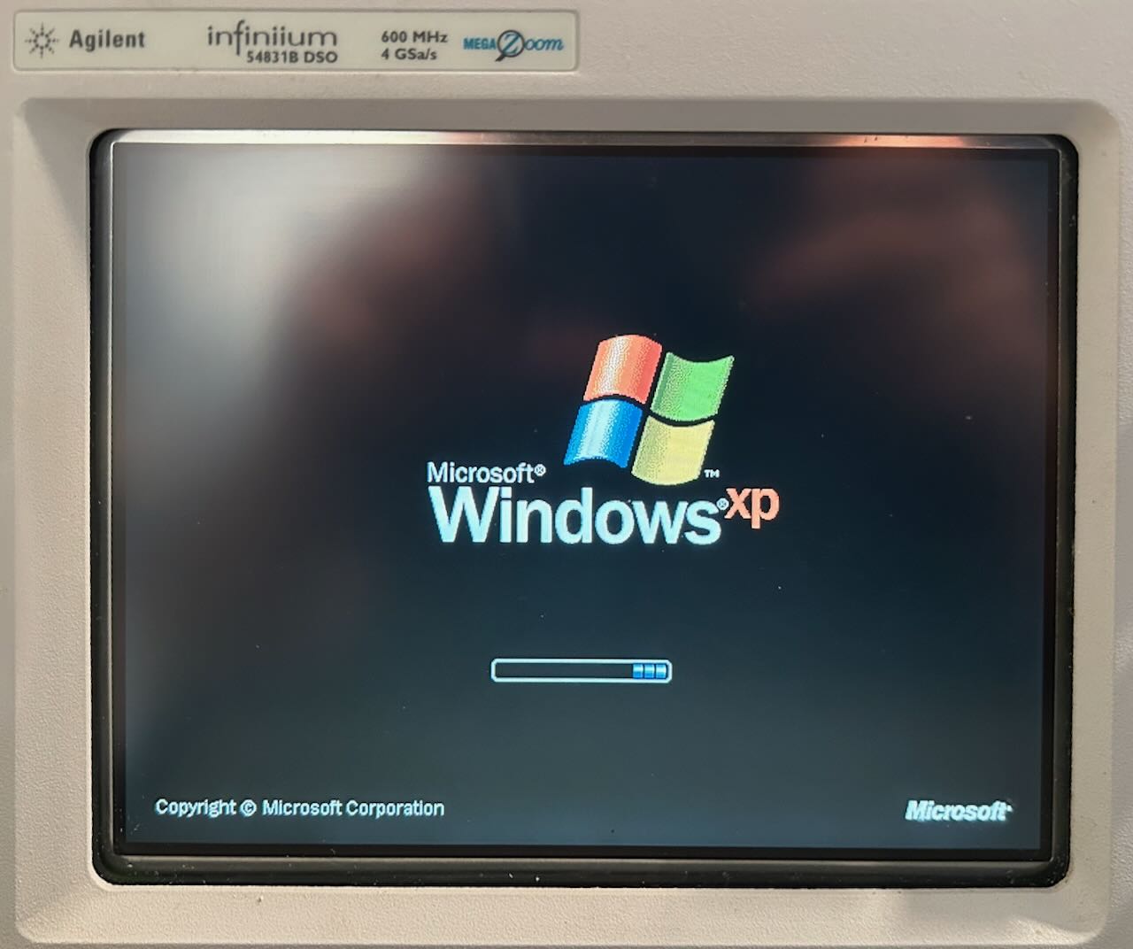
Once done, install the CF card into the scope and boot. The image that you installed on the drive contains a Symantec Ghost sub-image. When you boot the scope, you should see a Windows 98 splash screen (not WinXP!) and Symantec Ghost. Follow the instructions of the PDF file and eventually, it will end like this:
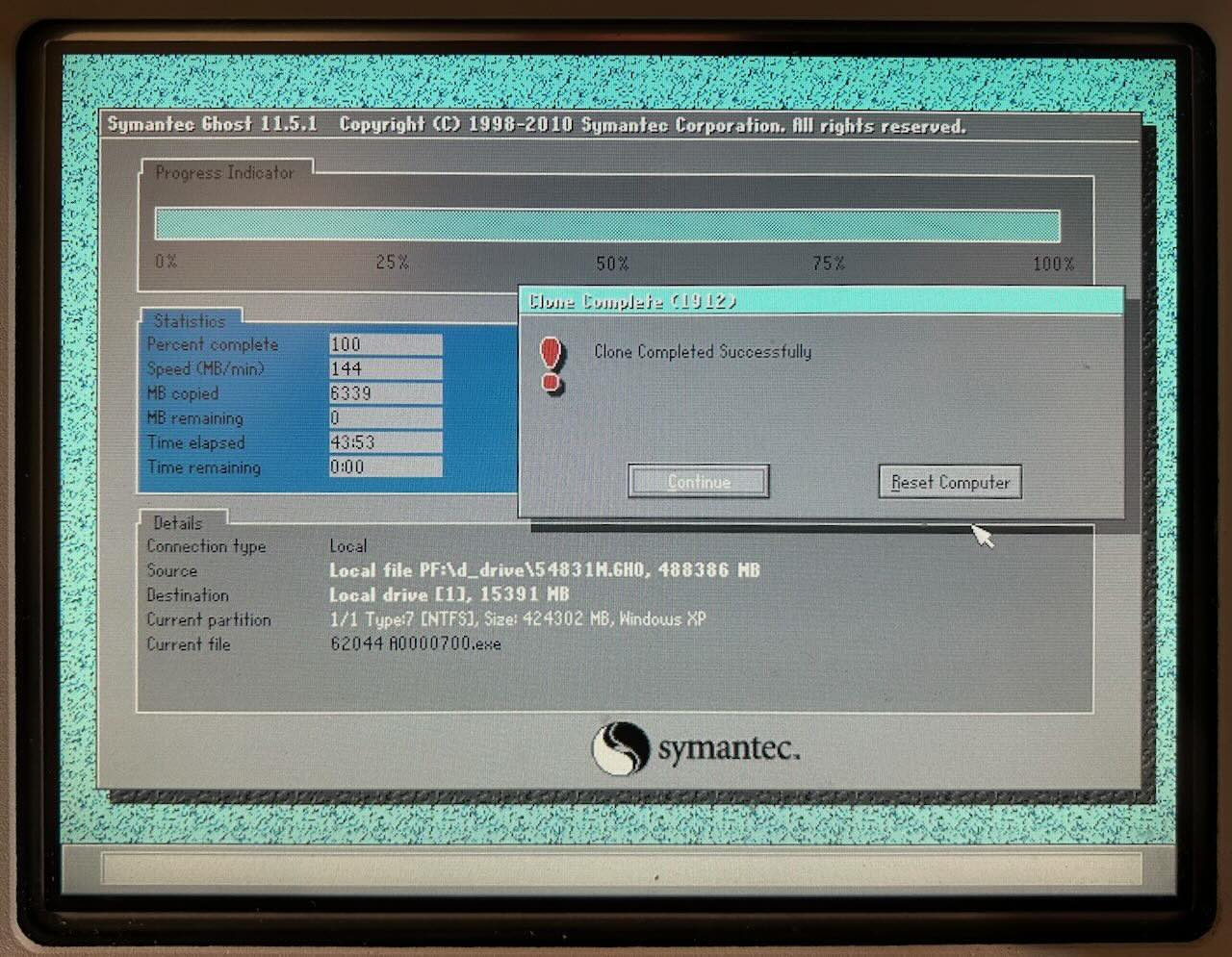
Reboot again, and you’ll see this, finally:
And this:
The software is functional, but there’s an awful lot of noise on those signals. If you’re seeing that, don’t worry: this happens when the scope isn’t calibrated. Go to “Calibration” in one of the menus, let it run all the way, it takes around 1 hour, and the noise should be gone. Hurray!
CPU Temperature Alarm
After a while, the scope gave off this persistent alarm:
According to the VP22 motherboard manual, the alarm can go off for 3 reasons: case open (there was no such sensor, so that didn’t apply), CPU temperature alarm, or CPU voltage alarm.
I assumed a CPU voltage alarm due to old capacitors, but to be really sure, you can go into the PC Health Status section of the BIOS menu and disable the CPU temperature alarm:
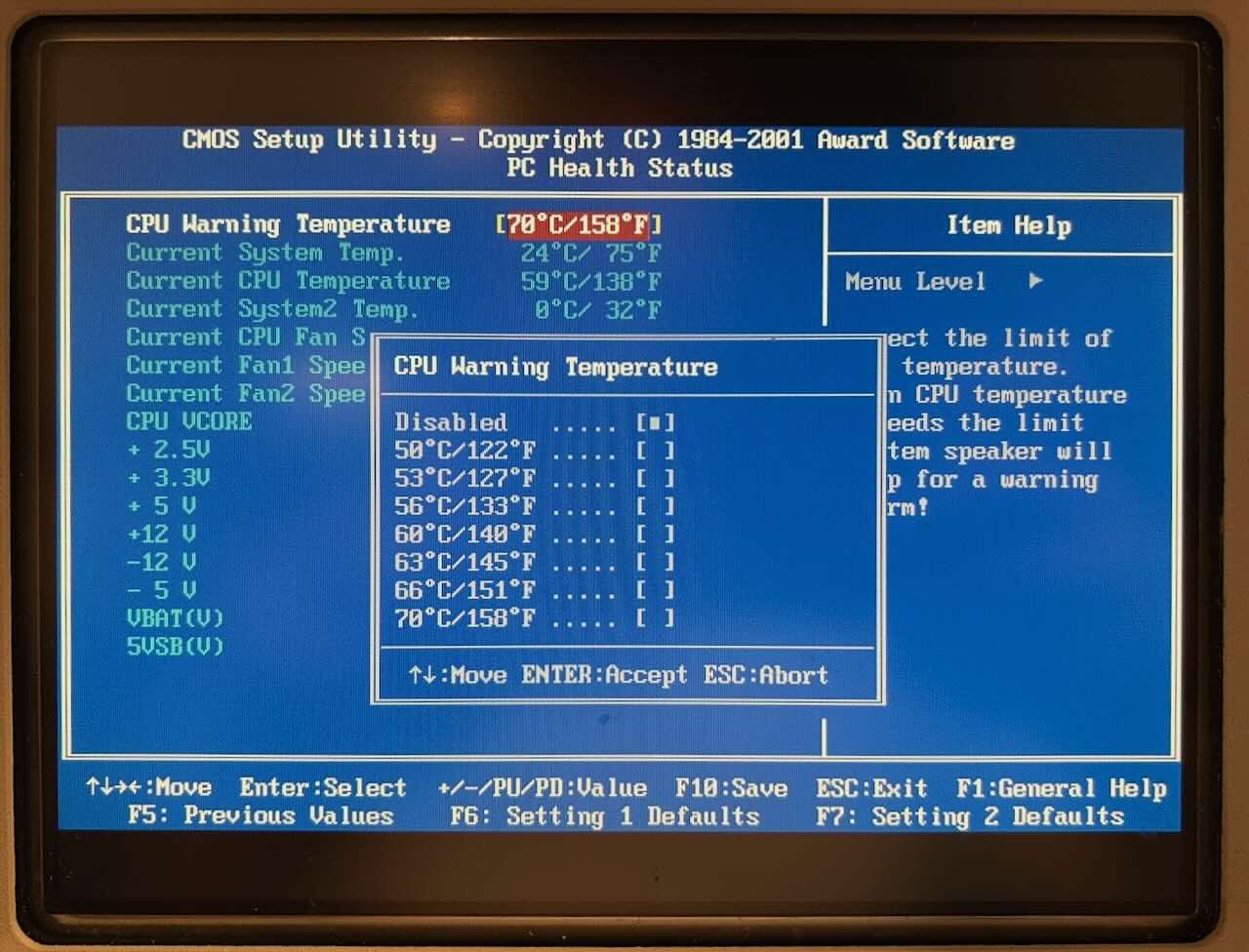
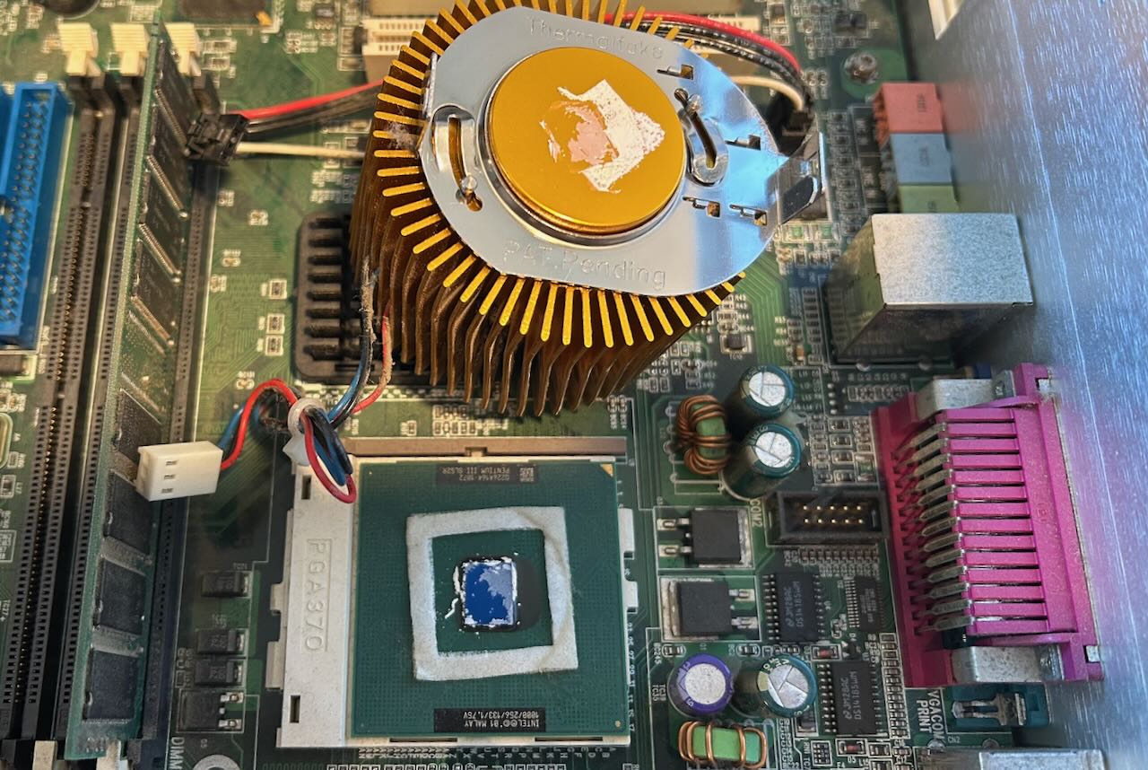
This made the alarm go away. That’s great because it’s much easier to fix the temperature than to replace the capacitors on the motherboard or the main power supply: apply thermal paste, reseat the cooler.
The temperature of the CPU in the BIOS screen was 64C. This is not very high by today’s standards, but the Pentium III thermal design guide sets a maximum junction temperature of 75C.
One of the benefits of running Windows XP is that many tools and USB memory sticks just work. I installed Core Temp to continuously monitor the temperatures after adding thermal paste and reseating the cooler.
Note that it is really important that you feel a subtle click when you rotate the cooler counter-clockwise to secure it in place. At the same time, you can’t rotate too hard because the metal tabs on the CPU socket can shear off or you can crack the CPU die.
Here’s the result after:
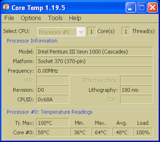
At rest, with the scope app disabled, I saw temperatures around 40C. When the scope was running with the CPU pegged at 100%, temperatures never exceeded 65C.
I still disabled the CPU temperature alarm though, because that beeping is way too annoying. This will probably come back to bite me some time in the future…
The scope was really working fine now, there was just one more thing to do.
Upgrade to 1 GHz Bandwidth
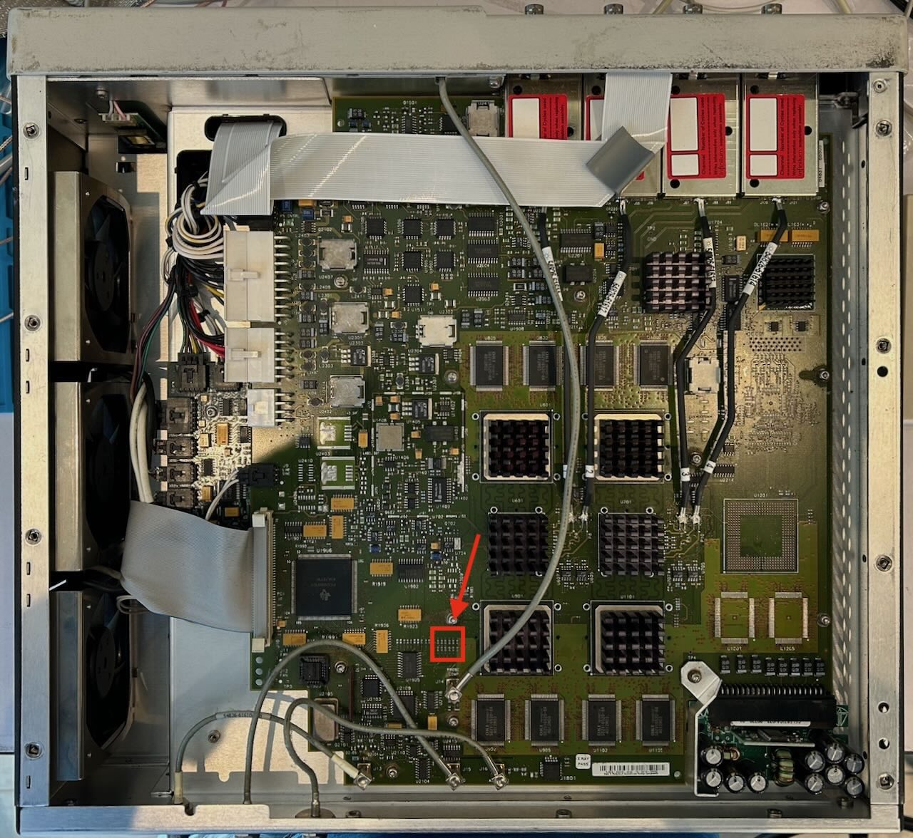
As mentioned earlier, the scope can be upgraded to a 54832 with 1 GHz bandwidth by removing a single resistor on the acquisition board.
The resistor array can be found here:
 (Click to enlarge)
Before the modification, all resistors should be present:
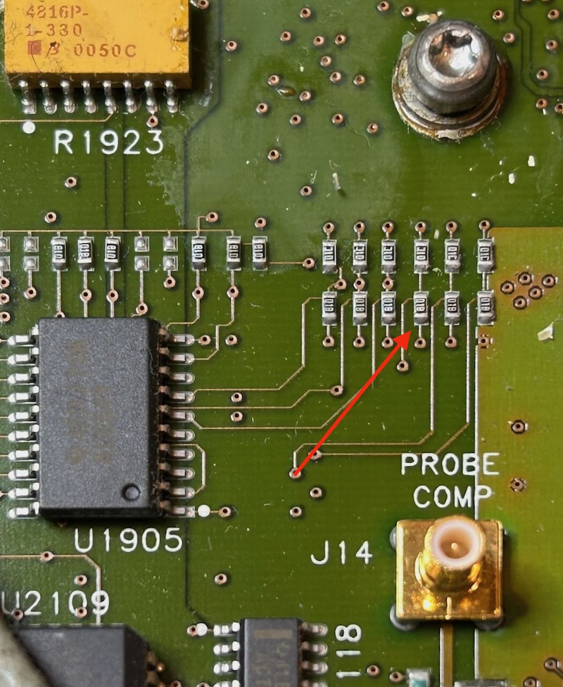
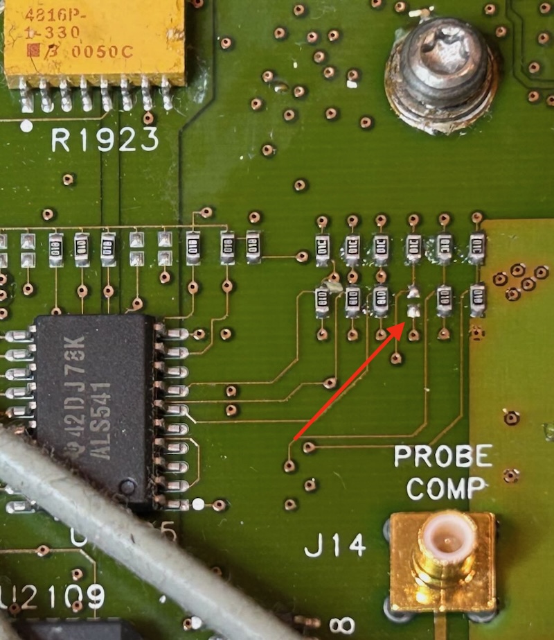
Remove this resistor for the upgrade:
After rebooting, the scope identifies itself as an Agilent 54832B:
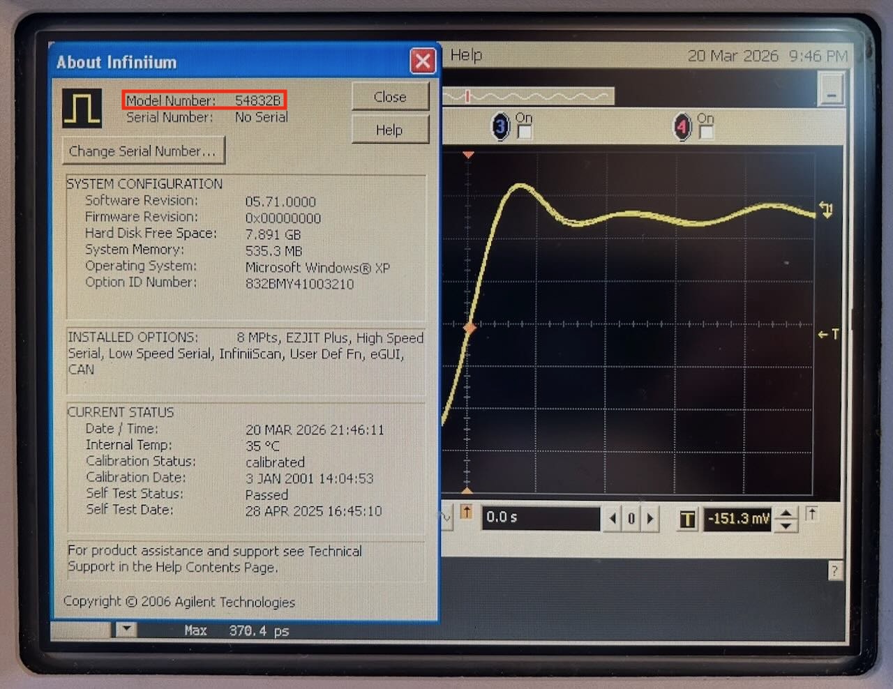
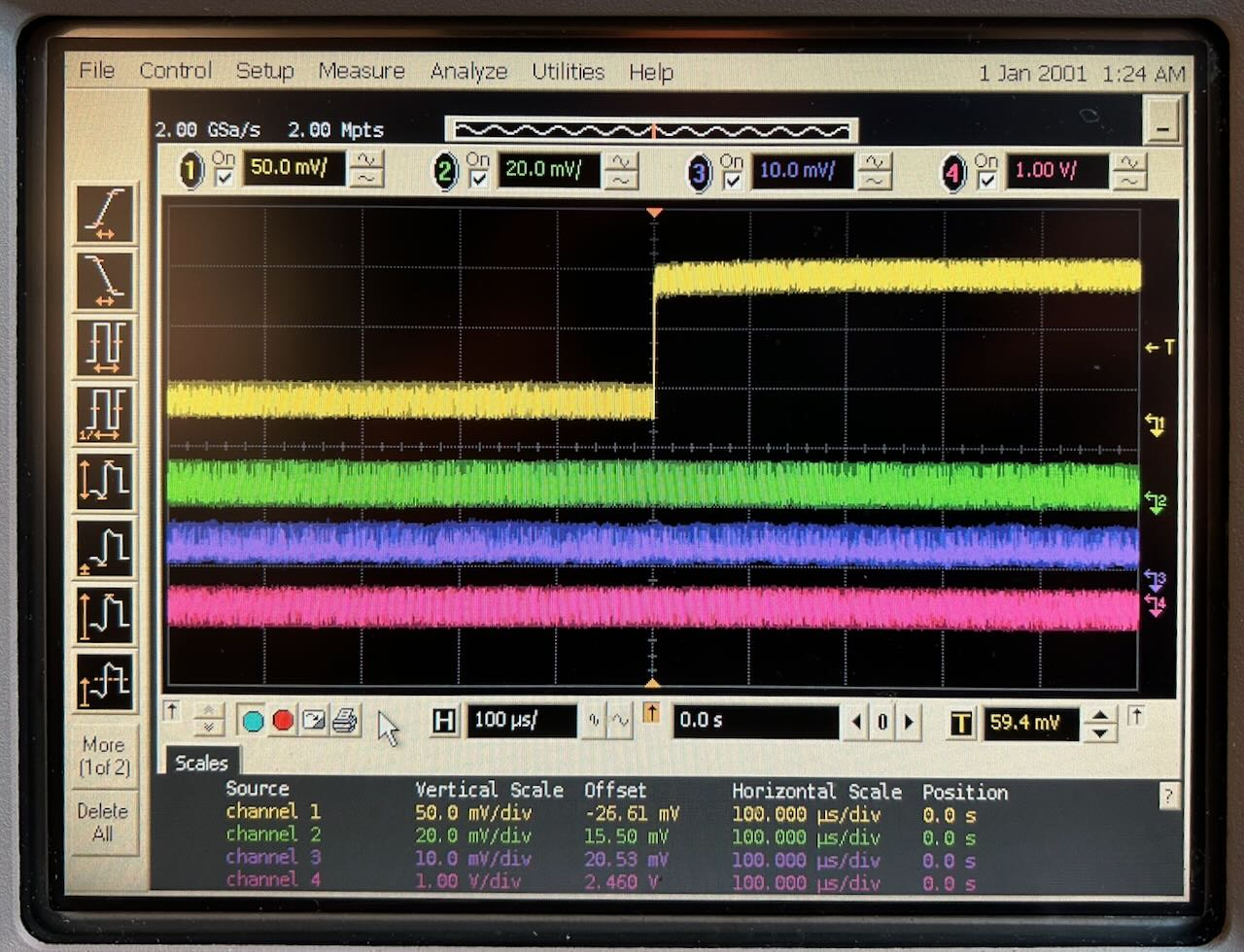
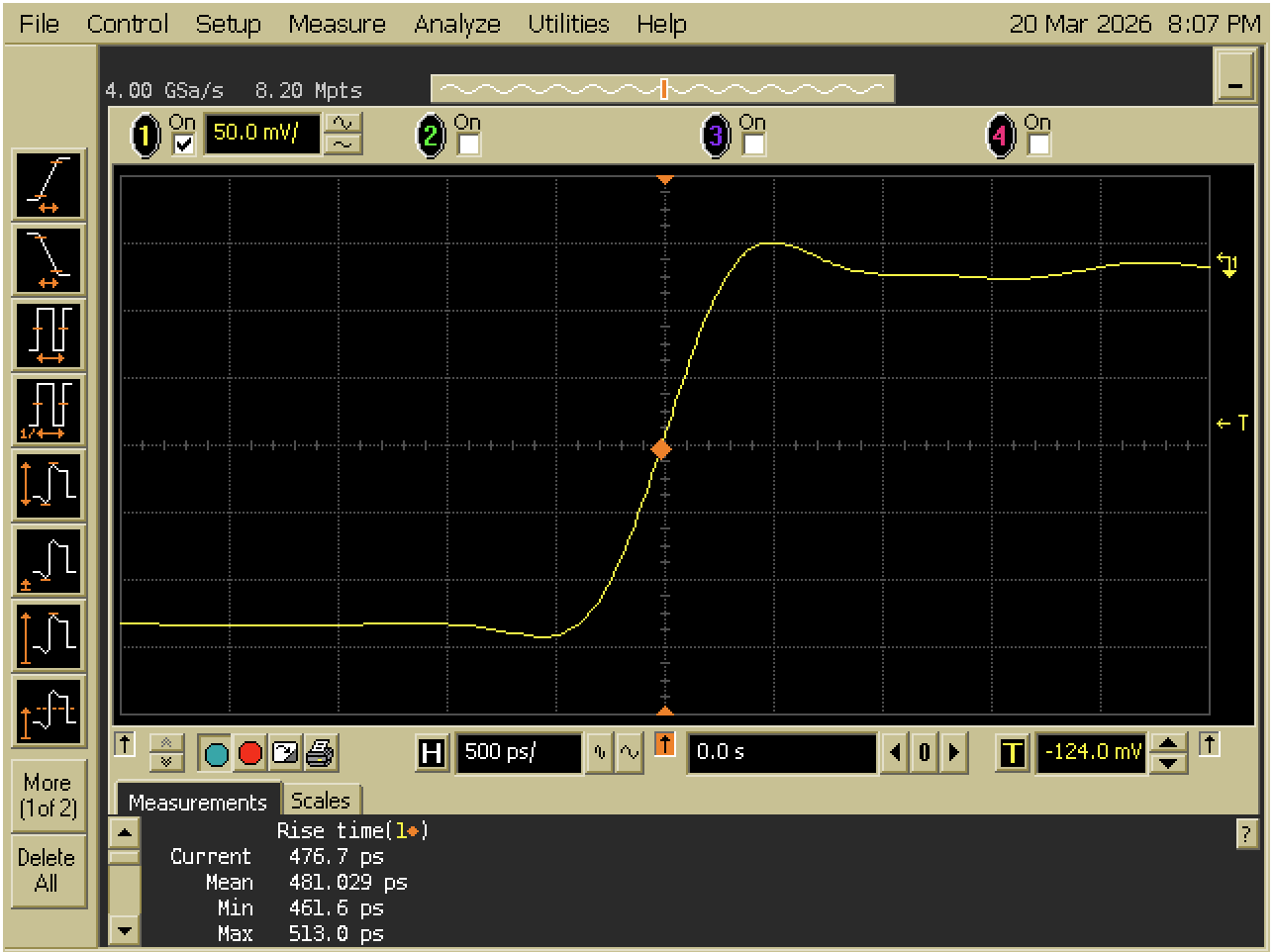
To test the modification, I fed the AUX Out4 signal at the back of the scope into channel 1, with 50 Ohm termination active.
Before the mod, the rise time averaged to 481 ps:
After removing the resistor, it dropped to 331 ps:
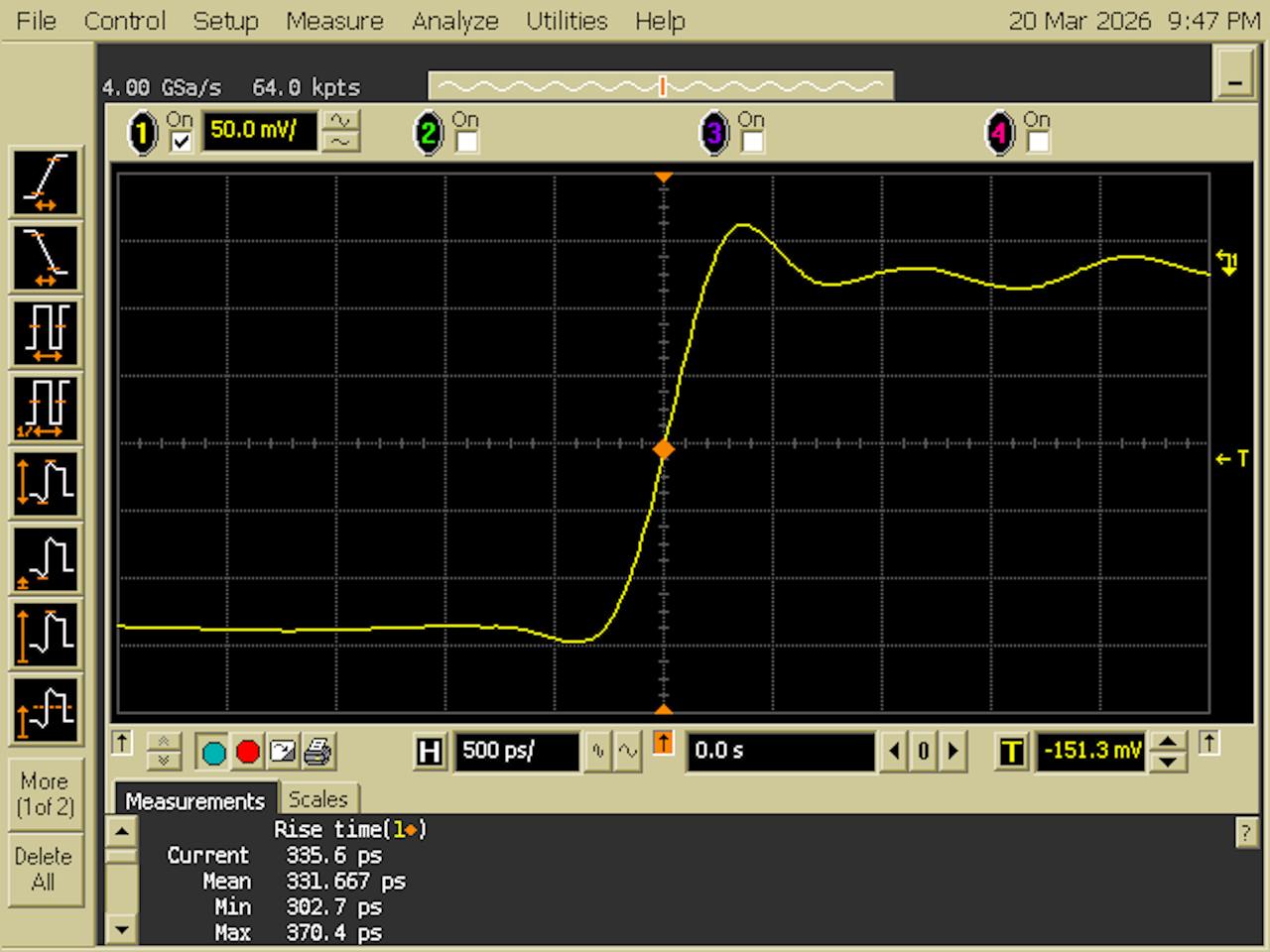
The scope bandwidth is calculated as 0.35 / t_rise. Going from 481 to
331 ps is an increase of 727 MHz to 1057 MHz. The modification worked and
the result is within spec, but others have reported an increase to 1.2 GHz. It’s
possible that my measurement is limited by the rise time of the AUX Out signal,
and that I’d see even better numbers with a real pulse generator. That’s for
another time…
Additional Changes are Possible
I only did the minimum to get the scopes working, and did the resistor mod. You can find more impressive modifications on the EEVblog forum:
- Install motherboards with P4 CPUs. This requires some mechanical surgery to the case as well, to make the connectors fit.
- Use faster SSDs than my compact flash cards. This can bring down the boot time from 4 minutes to less than a minute.
- Replace the 640x480 LCD screen with a 1024x768 LCD screen.
Some of these modifications may depend on each other. E.g. the larger resolution LCD screen requires an integrated GPU that is not present on the VP22 motherboard.
I decided not to do any of them: the scope works well enough for my needs.
Conclusion
For $200 and around $30 in additional components, I got myself 2 working 4 Gsps scopes with 600 MHz or 1 GHz bandwidth. I already sold unit A for $200, which I think is an excellent deal for the buyer. I’m keeping the other one.
All words in this blog post were written by a human.
References
EEVblog forum
- Agilent 600MHz 54831B hack for 1GHz 54832B possible? YES!
- Agilent 54831D modernising
- Agilent 54831M upgrade to Windows XP, guide and resources
Other info
-
Instead of cutting off the existing 5V connector for the CompactFlash adapter, I could have gotten the 5V from somewhere else on the motherboard.
Footnotes
-
I’m still not used to the recent renaming of HP into Agilent and often use their names interchangeably. ↩
-
The 54825A has a sleeve-like enclosure. ↩
-
You shouldn’t try this yourself because it can damage the electronics, but if you unplug the bridge cable while the scope is up and running, you’ll see that the GUI is still rendered but the waveforms disappear. ↩
-
Make sure to select the 10 MHz output for AUX Out in the Calibration menu. ↩