Power Switch and Battery Replacement of an SR620 Universal Time Interval Counter
- Introduction
- The SR620
- Repairing the SR620
- Replacing the Backup 3V Lithium Battery
- Switching to an External Reference Clock
- Running Auto-Calibration
- Oscilloscope Display Mode
- References
- Footnotes
Introduction
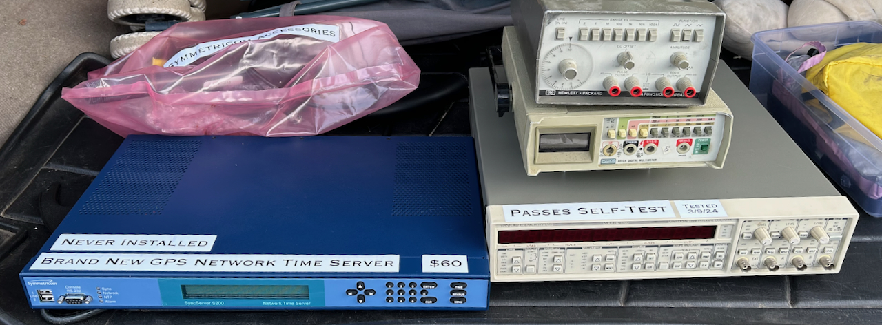
A little over a year ago, I found a Stanford Research Systems SR620 universal time interval counter at the Silicon Valley Electronics Flea Market. It had a big sticker “Passes Self-Test” and “Tested 3/9/24” (the day before the flea market) on it so I took the gamble and spent an ungodly $4001 on it.
Luckily, it did work fine, initially at least, but I soon discovered that it sometimes got into some weird behavior after pressing the power-on switch.
The SR620
The SR620 was designed sometime in the mid-1980s. Mine has a rev C PCB with a date of July 1988, 37 year old! The manual lists 1989, 2006, 2019 and 2025 revisions. I don’t know if there were any major changes along the way, but I doubt it. It’s still for sale on the SRS website, starting at $5150.
The specifications are still pretty decent, especially for a hobbyist:
- 25 ps single shot time resolution
- 1.3 GHz frequency range
- 11-digit resolution over a 1 s measurement interval
The SR620 is not perfect, one notable issue is its thermal design. It simply doesn’t have enough ventilation holes, the heat-generating power regulators are located close to the high precision time-to-analog converters, and the temperature sensor for the fan is inexplicably placed right next to the fan, which is not close at all to the power regulators. The Signal Path has an SR620 repair video that talks about this.
Repairing the SR620
You can see the power-on behavior in the video below:
Of note is that lightly touching the power button changes the behavior and sometimes makes it get all the way through the power-on sequence. This made me hopeful that the switch itself was bad, something that should be easy to fix.
Unlike my still broken SRS DG535, another flea market buy with the most cursed assembly, the SR620 is a dream to work on: 4 side screws is all it takes to remove the top of the case and have access to all the components from the top. Another 4 screws to remove the bottom panel and you have access to the solder side of the PCB. You can desolder components without lifting the PCB out of the enclosure.
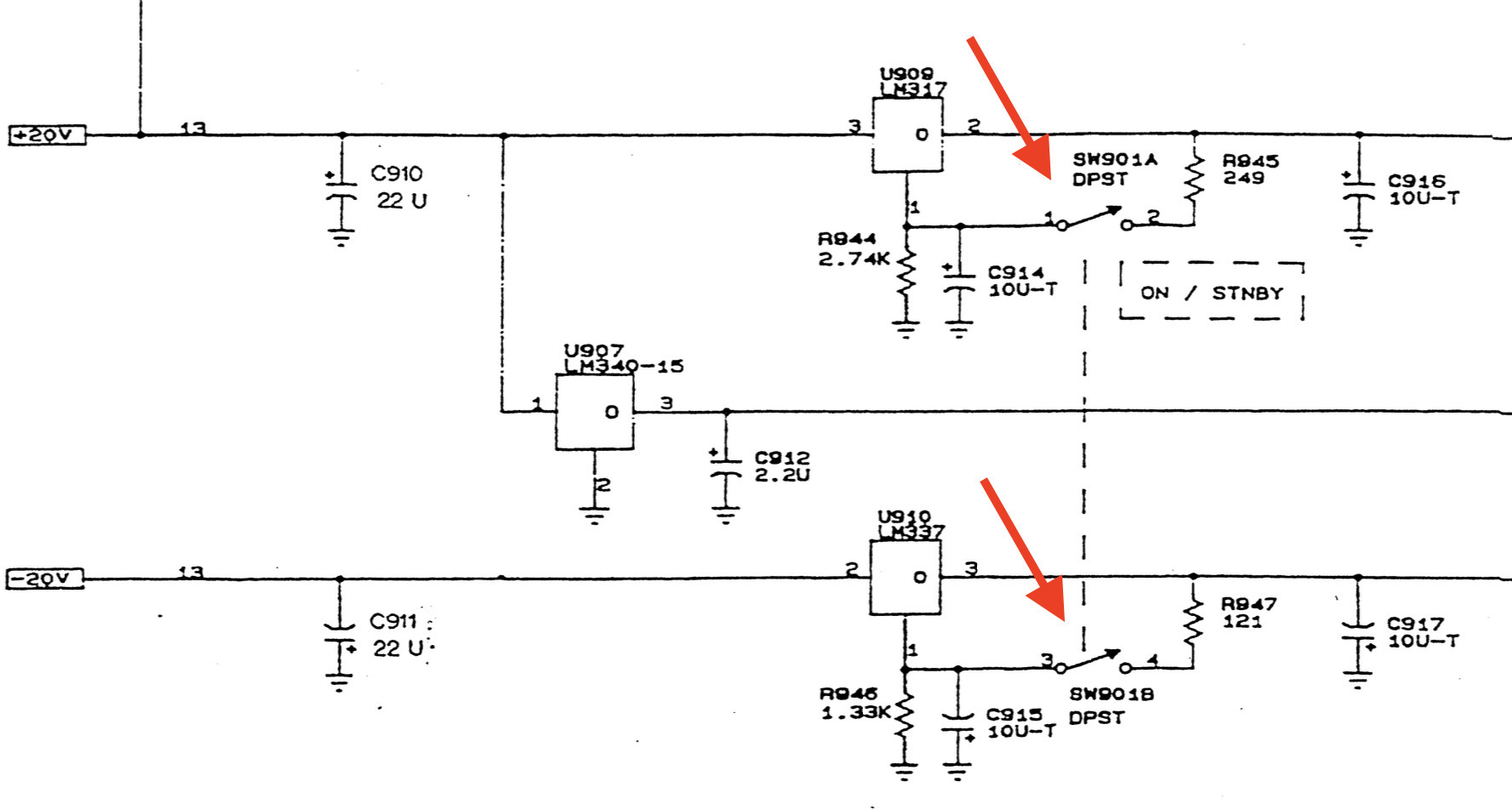
Like my HP 5370A, the power switch of the SR620 selects between power on and standby mode. The SR620 enables the 15V rail at all times to keep a local TCXO or OCXO warmed up.
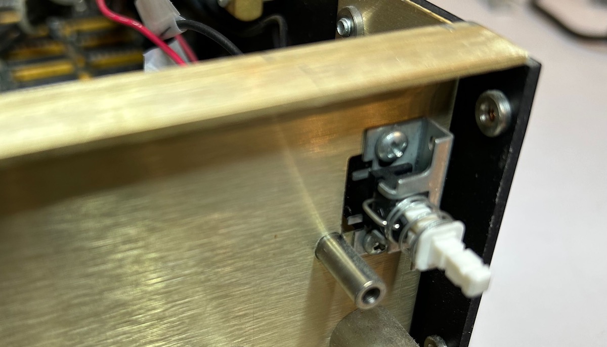
The power switch is located at the right of the front panel. It has 2 black and 2 red wires. When the unit is powered on, the 2 black wires and the 2 red wires are connected to each other.
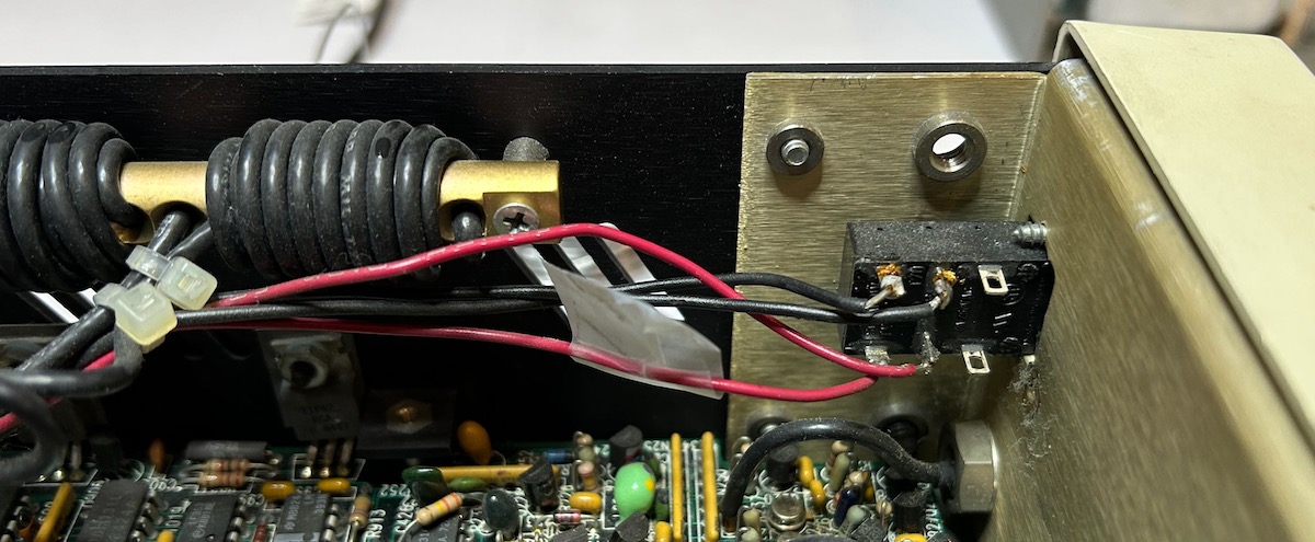
To make sure that the switch itself was the problem, I soldered the wires together to create a permanent connection:
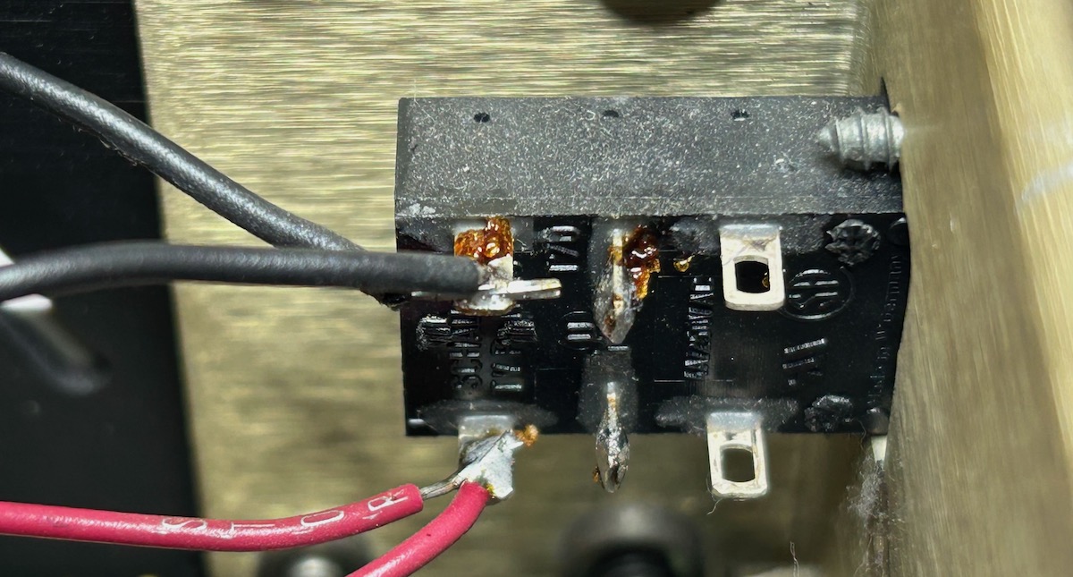
After this, the SR620 worked totall fine! Let’s replace the switch.
Unscrew 4 more screws and pull the knobs of the 3 front potentiometers and power switch to get rid of the front panel:
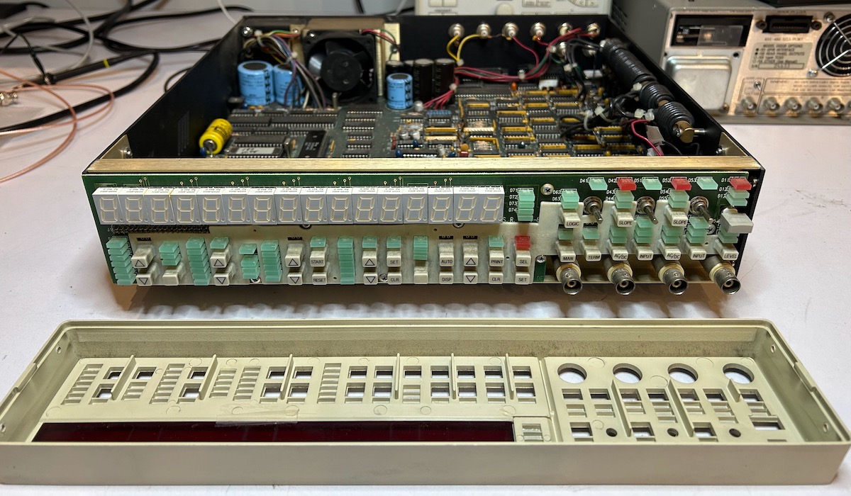
A handful of additional screws to remove the front PCB from the chassis, and you have access to the switch:
The switch is an ITT Schadow NE15 T70. Unsurprisingly, these are not produced anymore, but you can still find them on eBay. I paid $7.5 + shipping, the price increased to $9.5 immediately after that. According to this EEVblog forum post, this switch on Digikey is a suitable replacement, but I didn’t try it.
The old switch (bottom) has 6 contact points vs only 4 of the new one (top), but that wasn’t an issue since only 4 were used. Both switches also have a metal screw plate, but they were oriented differently. However, you can easily reconfigure the screw plate by straightening 4 metal prongs.
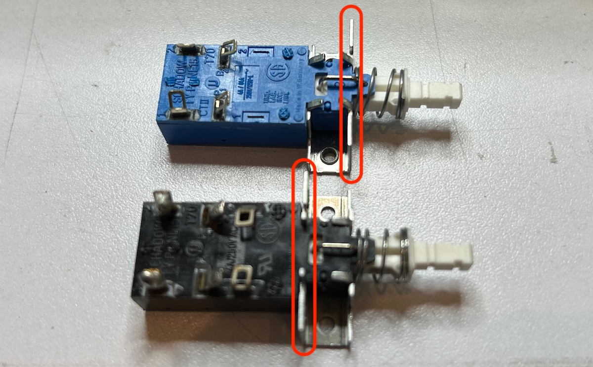
If you buy the new switch from Digikey and it doesn’t come with the metal screw plate, you should be able to transplant the plate from the broken switch to the new one just the same.
To get the switch through the narrow hole of the case, you need to cut off the pins on the one side of the switch and you need to bend the contact points a bit. After soldering the wires back in place, the SR620 powered on reliably.
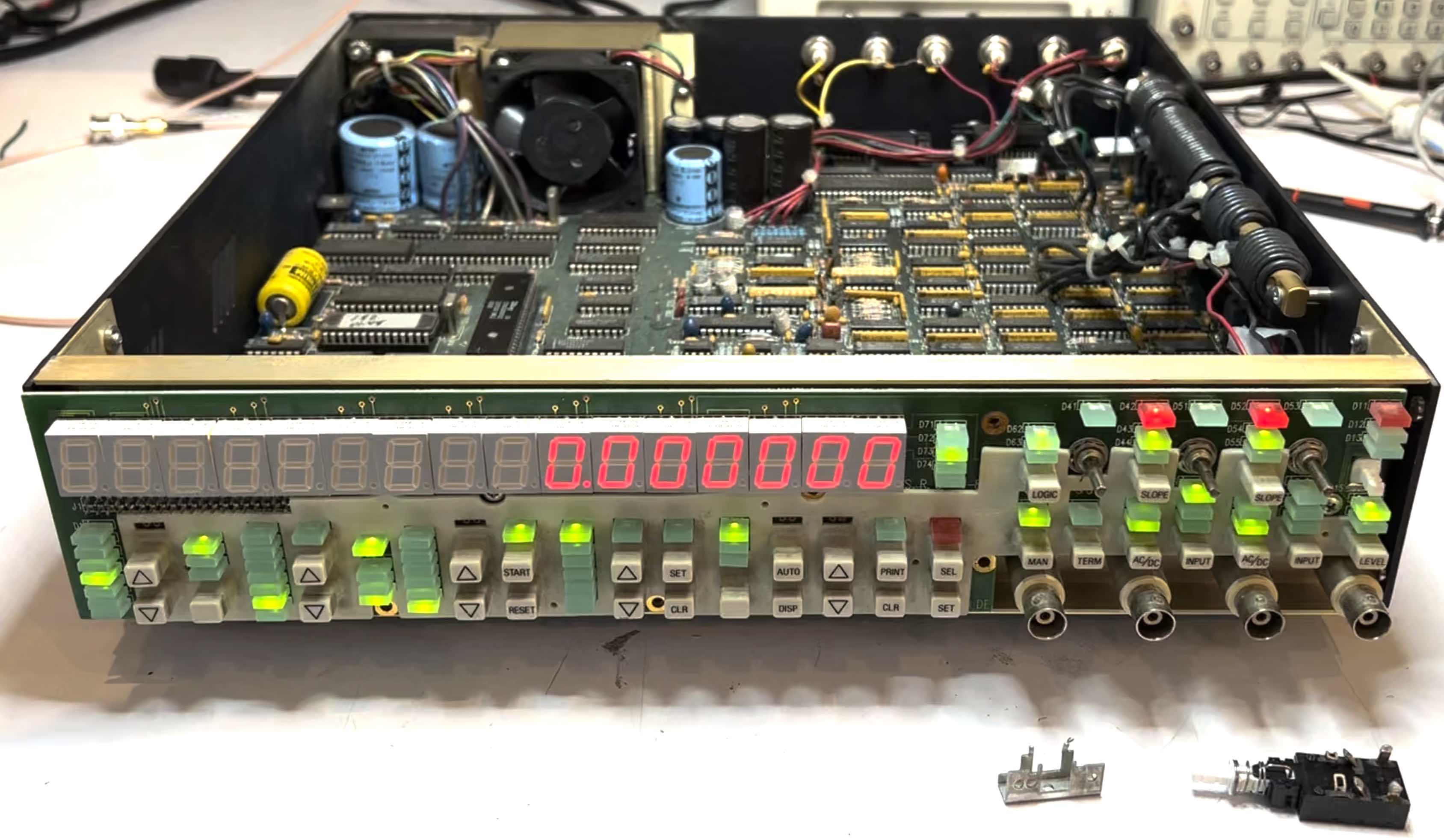
Switch replacement completed!
Replacing the Backup 3V Lithium Battery
The SR620 has a simple microcontroller system consists of a Z8800 CPU, 64 KB of EPROM and a
32 KB SRAM. In addition to program data, the SRAM also contains calibration and settings.
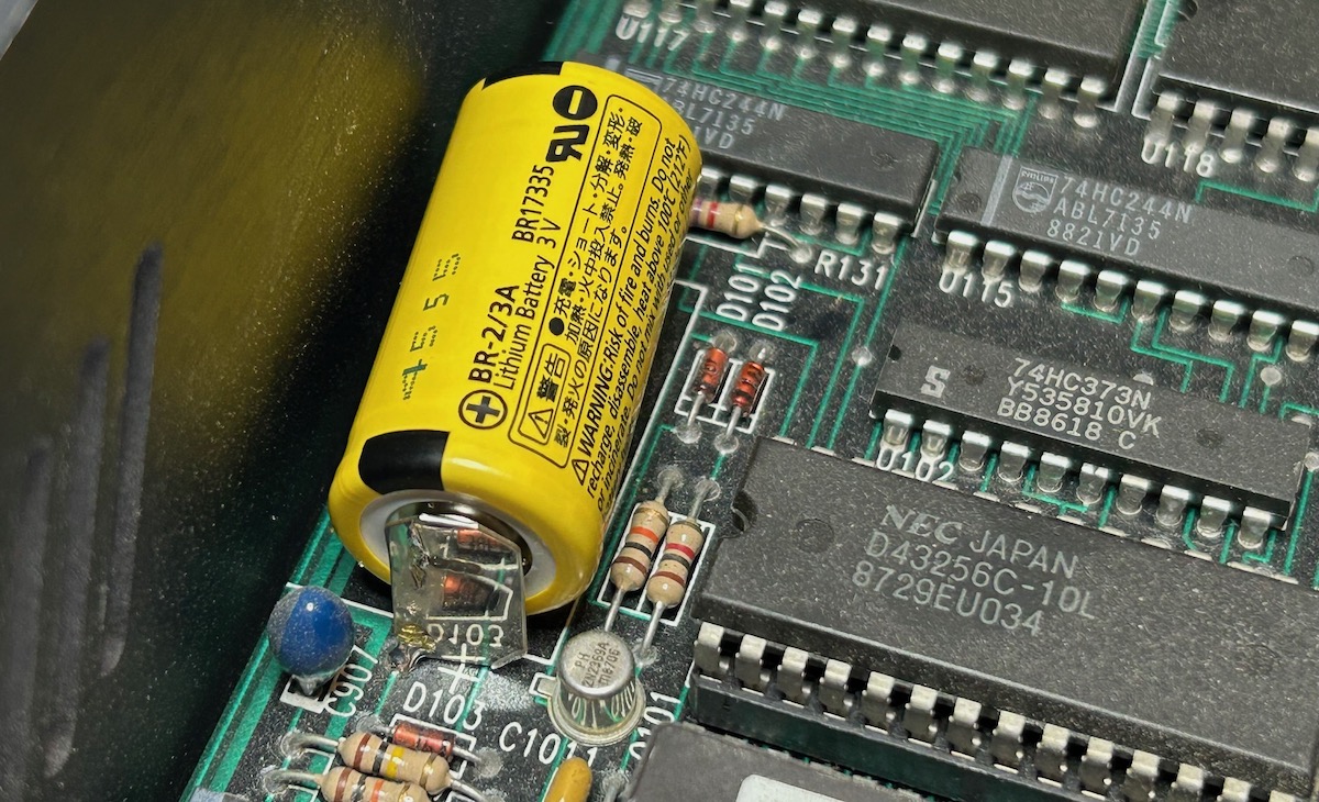
To retain its contents when the AC power plug is removed, a non-recharchable 3V Panasonic BR-2/3A
lithium battery keeps this SRAM powered at all times. You can find this battery in many old pieces
of test equipment, I already
replaced one such battery in my HP 3478A multimeter.

These batteries last almost forever, but mine had a 1987 date code and 38 years is really pushing things, so I replaced it with this new one from Digikey.
The 1987 version of this battery had 1 pin on each side, on the new ones, the + side has 2 pins, so you need to cut one of those pins and install the battery slightly crooked back onto the PCB.
When you first power up the SR620 after replacing the battery, you might see “Test Error 3” on the display. According to the manual:
Test error 3 is usually “self-healing”. The instrument settings will be returned to their default values and factory calibration data will be recalled from ROM. Test Error 3 will recur if the Lithium battery or RAM is defective.
After power cycling the device again, the test error was gone and everything worked, but with a precision that was slightly lower than before: before the battery replacement, when feeding the 10 MHz output reference clock into channel A and measuring frequency with a 1s gate time, I’d get a read-out of 10,000,000.000N MHz. In other words: around a milli-Hz accuracy. After the replacment, the accuracy was about an order of magnitude worse. That’s just not acceptable!
The reason for this loss in accuracy is because the auto-calibration parameters were lost. Luckily, this is easy to fix.
Switching to an External Reference Clock
My SR620 has the cheaper TCXO option which gives frequency measurement results that are about one order of magnitude less accurate than using an external OCXO based reference clock. So I always switch to an external reference clock. The SR620 doesn’t do that automatically, you need to manually change it in the settings, as follows:
- SET -> “ctrl cal out scn”
- SEL -> “ctrl cal out scn”
- SET -> “auto cal”
- SET -> “cloc source int”
- Scale Down arrow -> “cloc source rear”
- SET -> “cloc Fr 10000000”
- SET
If you have a 5 MHz reference clock, use the down or up arrow to switch between 1000000 and 5000000.
Running Auto-Calibration
You can rerun auto-calibration manually from the front panel without opening up the device with this sequence:
- SET -> “ctrl cal out scn”
- SEL -> “ctrl cal out scn”
- SET -> “auto cal”
- START
The auto-calibration will take around 2 minutes. Only run it once the device has been running for a while to make sure all components have warmed up and are at stable temperature. The manual recommends a 30 minute warmup time.
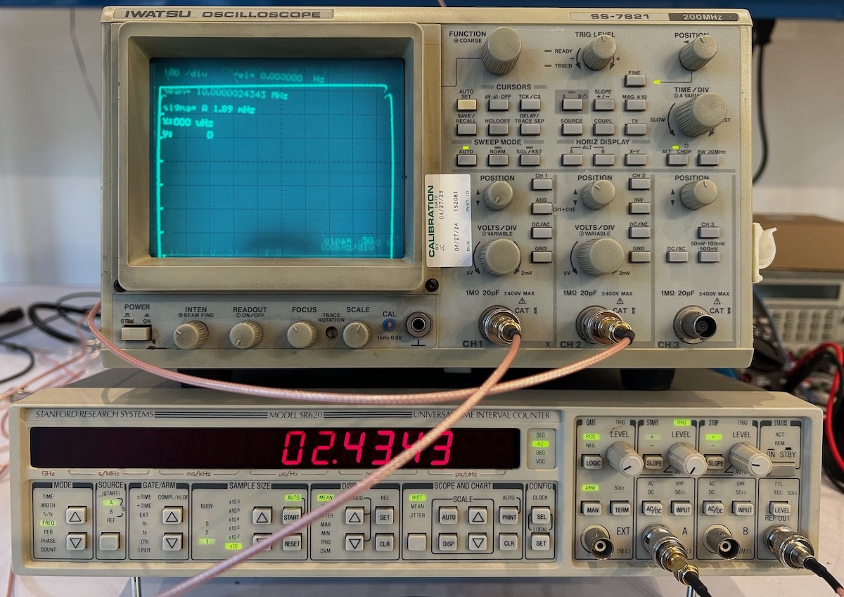
After doing auto-calibration, feeding back the reference clock into channel A and measuring frequency with a 1 s gate time gave me a result that oscillated around 10 MHz, with the mHz digits always 000 or 999.2
It’s possible to fine-tune the SR620 beyond the auto-calibration settings. One reason why one might want to do this is to correct for drift of the internal oscillator To enable this kind of tuning, you need to move a jumper inside the case. The time-nuts email list has a couple of discussions about this, here is one such post. Page 69 of the SR620 manual has detailed calibration instructions.
Oscilloscope Display Mode
When the 16 7-segment LEDs on the front panel are just not enough, the SR620 has this interesting way of (ab)using an oscilloscope as general display: it uses XY mode to paint the data.
I had tried this mode in the past with my Sigilent digital oscilloscope, but the result was unreadable: for this kind of rendering, having a CRT beam that lights up all the phosphor from one point to the next is a feature, not a bug. This time, I tried it with an old school analog oscilloscope3:
 (Click to enlarge)
The result is much better on the analog scope, but still very hard to read. When you really need all the data you can get from the SR620, just use the GPIB or RS232 interface.
References
- The Signal Path - TNP #41 - Stanford Research SR620 Universal Time Interval Counter Teardown, Repair & Experiments
- Some calibration info about the SR620
-
Fast High Precision Set-up of SR 620 Counter
The rest of this page has a bunch of other interesting SR620 related comments.
Time-Nuts topics
The SR620 is mentioned in tons of threads on the time-nuts emaiml list. Here are just a few interesting posts:
-
This post talks about some thermal design mistakes in the SR620. E.g. the linear regulators and heat sink are placed right next to the the TCXO. It also talks about the location of the thermistor inside the fan path, resulting in unstable behavior. This is something Shrirar of The Signal Path fixed by moving the thermistor.
-
This comment mentions that while the TXCO stays powered on in standby, the DAC that sets the control voltage does not, which results in an additional settling time after powering up. General recommendation is to use an external 10 MHz clock reference.
-
This comment talks about warm-up time needed depending on the desired accuracy. It also has some graphs.
Footnotes
-
This time, the gamble paid off, and the going rate of a good second hand SR620 is quite a bit higher. But I don’t think I’ll ever do this again! ↩
-
In other words, when fed with the same 10 MHz as the reference clock, the display always shows a number that is either 10,000,000,000x or 9,999,999,xx. ↩
-
I find it amazing that this scope was calibrated as recently as April 2023. ↩