HP 3478A Multimeter Calibration Data Backup and Battery Replacement
- Introduction
- Replacing the Capacitors
- HP 3478A Calibration Data Backup, Format, and Restore
- Replacement 3V Battery
- SRAM Power Circuit
- Swapping the Battery
- References
Introduction
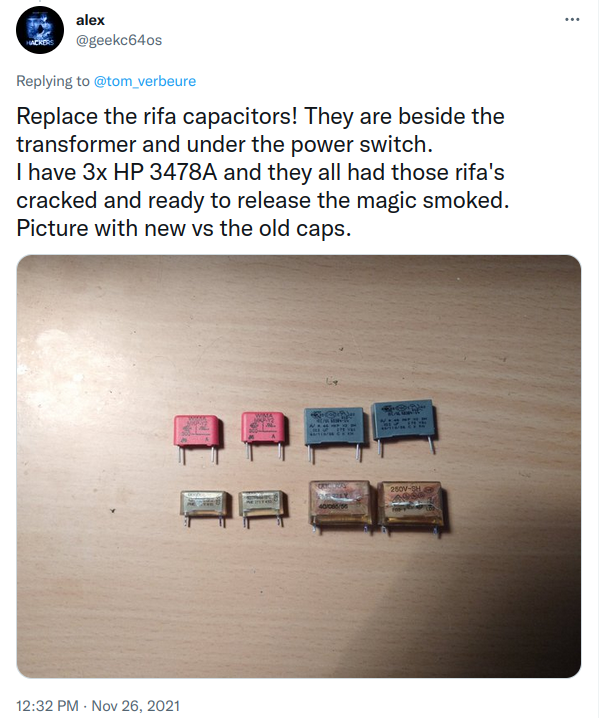
Just a bit of a year ago, I wrote a blog post about repairing an HP 3478A multimeter with a hacksaw. After posting a link on Twitter, @alex commented that I should replace the RIFA capacitors because they have a tendency to go up in smoke:
The multimeter went back on the shelve, but I have now some projects in mind where I could use some continuous voltage recording. Now is a good time to replace the capacitors.
Another weak spot of the 3478A is that fact that calibration parameters are stored in a voltatile SRAM that’s permanentely powered on by a long-lasting 3V Lithium battery. There’s no explicit production date on my unit, but a bunch of chips were produced in 1988, so after almost 34 years, I might as well replace that one too.
There is a lot of information on the web about how to do this, though some info is buried in long forums threads on EEVBlog or (long winded) Youtube videos. This blog post tries to bring some of the information together.
Replacing the Capacitors
Unplug the power cable of the 3478A before soldering!
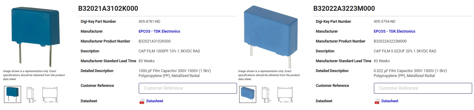
There’s really not a whole lot to write about the replacement process: I bought 2 B32021A3102K000 and 2 B32022A3223M000 capacitors, desoldered the old ones, and replaced them.
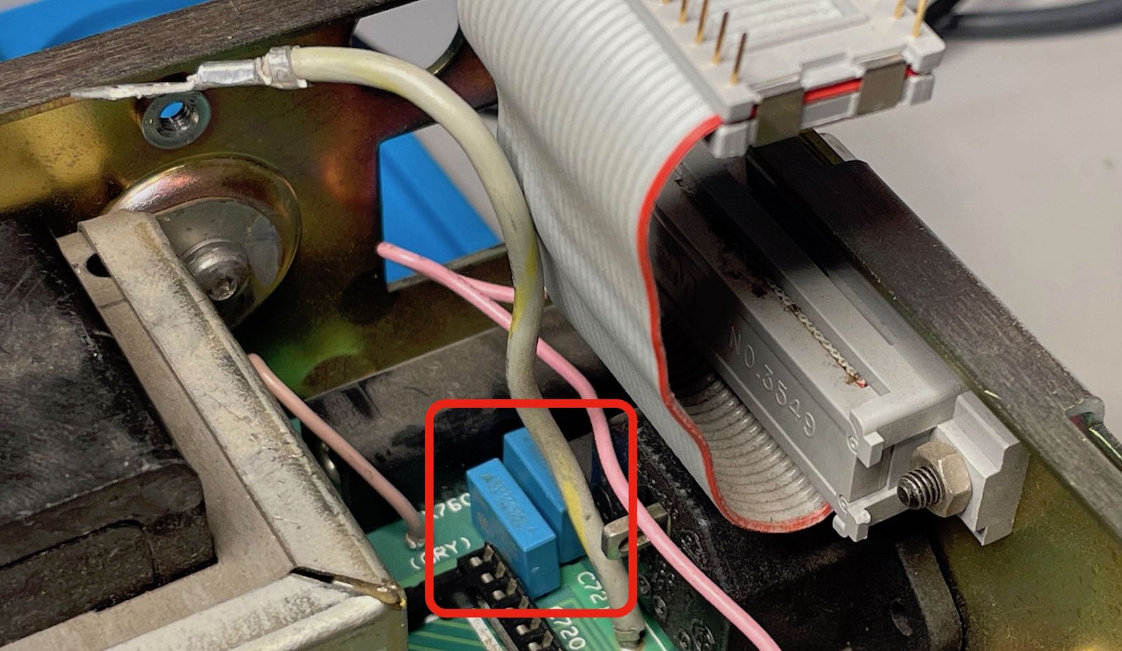
The 2 small RIFA caps can be found in the back, underneath the GPIB flat cable. You can see the replacements here:
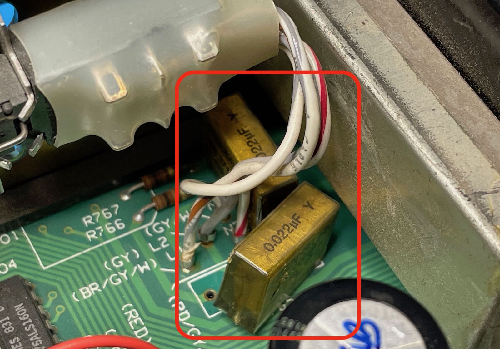
The 2 large RIFA caps are underneath the power switch:
In the case of the 2 smaller caps, I only had to remove unplug the flat cable and unscrew that gray wire. For the larger ones, I had to unscrew a larger transistor or power regulator that was attached to the metal case, and remove 2 screws to loosen the power switch.
After that, it was the usual fiddling to desolder through-hole components. My desolder pump, desolder wick, and desoldering needles were all useful.
The RIFA caps on my unit were in pretty decent conditions. Mine weren’t completely cracked, but you could start to see some hairlines in the polyester.
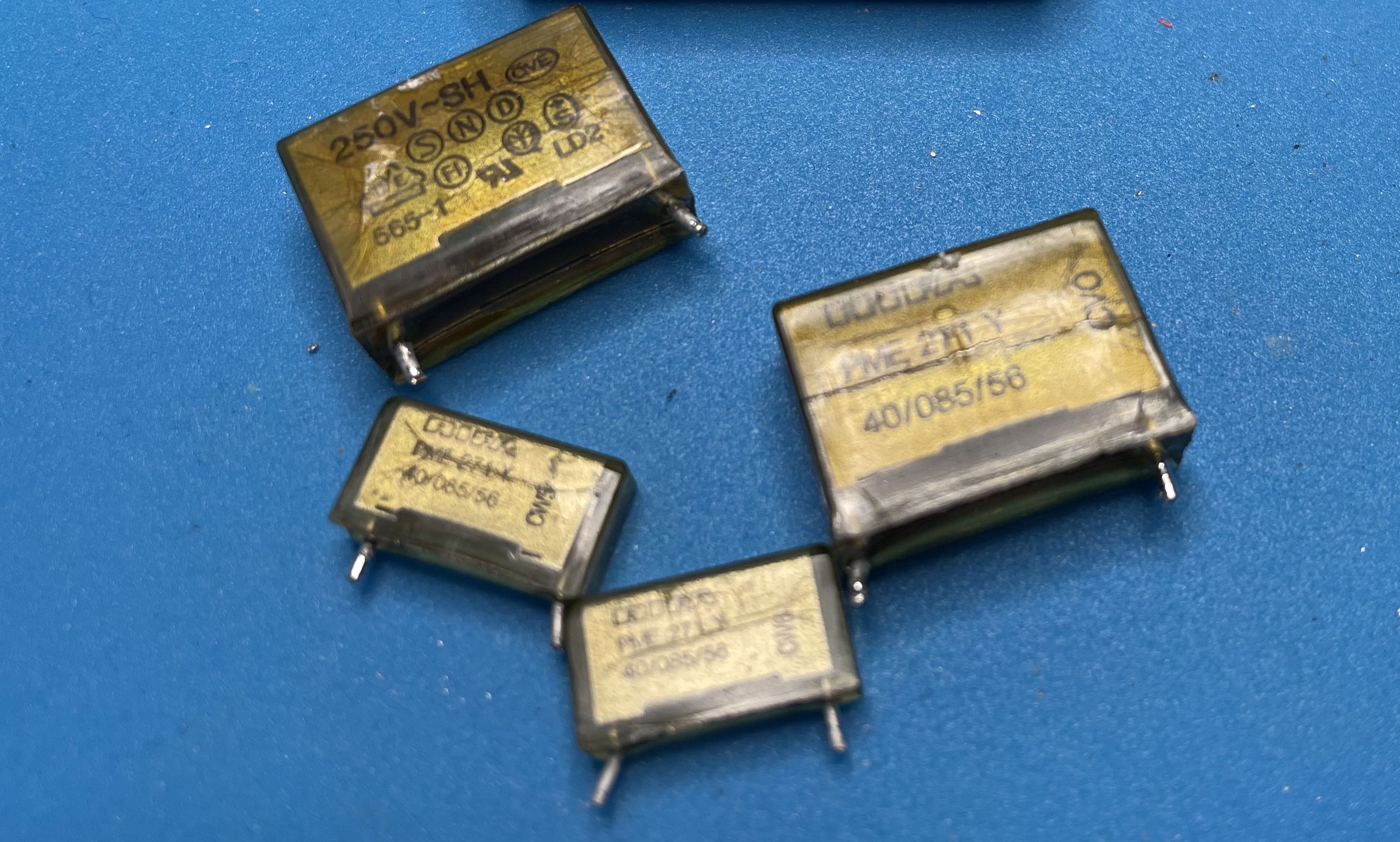
The insidious part of RIFA caps is that a part of an always-on AC mains circuit: when the instrument is powered off but plugged in, they still can catch fire!
It’s good that they’re gone now. Replacing the caps took about 45 minutes from start to finish.
HP 3478A Calibration Data Backup, Format, and Restore
These days, a working 3478A sells for around $150 on eBay. You’ll probably pay more just to have it professionally recalibrated, or to acquire reference voltage or resistor standards if you want to calibrate yourself, so most people will just keep using what they have. In many cases, you care more about measuring relative than absolute values anyway.
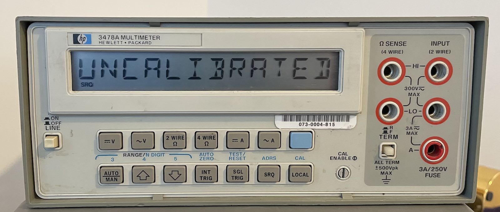
As mentioned earlier, the 3478A stores the calibration data in a 256x4 SRAM that’s “permanently” powered by a lithium battery. You should definitely replace the RIFA capacitors, there’s a real fire risk when they fail, but if you don’t want to replace the battery just yet, at least back up the calibration data so that you have a way out if you ever see the following message:
There are two ways to get the calibration data:
- Use the GPIB interface to read the SRAM contents.
- Probe the SRAM pins with a logic analyzer
Probing the SRAM pins
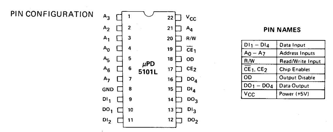
The uPD5105L SRAM has 22 pins, but only 20 of those are functional. Of those, you need to probe A[7:0], DO[3:0], and some pins to determine that the microcontroller is accessing the chip. CE2, pin 17, should do the trick.
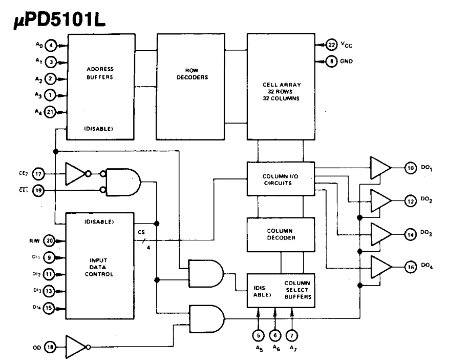
That’s a total of 13 pins.
Wiring up the probes is easy: the spacing of these old school DIL packages is a joy. You do need a 16-channel logic analyzer, which are quite a bit more expensive than these ubiquitous $15 8-channel Saleae clones. And even if you have access to the real deal, I had the problem that… it didn’t work: after wiring up the probes, my 3478A didn’t want to boot up!
Still, others have done it, so it’s definitely possible.
Dumping SRAM contents through the GPIB interface
The GPIB route is much easier. I used my Agilent 82357B GPIB-to-USB dongle. Check out my TDS 420A control over GPIB blog post for details on how to install the linux-gpib kernel drivers (what a pain…).
In a long discussion on EEVBlog, plenty of people post their own scripts and tools to dump the SRAM contents, but none of them fit my needs: they were either windows-only, used Matlab, required an old version of PyVISA, or used the linux-gpib kernel API directly.
I wanted to use the PyVISA API because it works for both Linux and Windows, so I just wrote my own version.
Reading the data is straightforward: when you send a W<addr> GPIB message to the 3478A,
it will reply with a single character that has an ASCII value from 64 to 79. Subtract
64 from that, and you get a 4-bit value, the SRAM content of the specified address.
Note that <addr> is a binary number, not the ASCII representation of the address!
Don’t worry about corrupting the calibration data with GPIB transactions: as long as the indent of the CAL ENABLE switch on the front panel is horizontal, it’s impossible for the microcontroller to write to the SRAM.
In Python, the code to fetch the 256 SRAM values looks like this:
def read_cal_data(hp3478a):
    cal_data = []

    for addr in range(0, 256):
        cmd = bytes([ord('W'), addr])

        hp3478a.write_raw(cmd)
        rvalue = ord(hp3478a.read()[0])
        assert rvalue >= 64 and rvalue < 80
        cal_data.append(rvalue-64)

    return cal_data
SRAM Data Checksum
The SRAM contents are organized as follows:
- Address 0 contains a read/write check nibble. The microcontroller does a read/write operation to it to check whether or not the SRAM is write protected.
- After that, there are 19 calibration entries of 13 nibbles.
In total that’s 248 SRAM values. The remaining ones are don’t-care.
Each of the 19 calibration entries is organized as follows:
-
11 nibbles with a real calibration value.
The first 6 nibbles specify an offset, the next 5 contain a gain. The coding method is a bit obscure and out of the scope of this blog post, but you can find the details here.
The same poster created hp3478a_utils, a DOS utility that decodes all the values.
Use the source of the utility as the golden reference: later in the EEVBlog thread, there were some corner cases where the initial gain encoding didn’t quite work.
-
2 nibbles that form an 8-bit checksum
The sum of the first 11 nibbles plus the sum of the 8-bit checksum must be 255 for a correct calibration value.
For example:
@@@A@IADOD@MM -> 0 0 0 1 0 9 1 4 F 4 0 D D -> 1+9+1+4+F+4+DD = 0xFF
Here’s the code that checks the validity of the SRAM contents:
def verify_checksum(cal_data):
    for entry in range(0,19):
        sum = 0
        for idx in range(0, 13):
            val = cal_data[entry*13 + idx + 1]
            if idx!=11:
                sum += val
            else:
                sum += val*16

        print("Checksum %2d: 0x%02x " % (entry,sum), end='')
        if sum==255:
            print(" PASS")
        else:
            print(" FAIL")
The 19 entries contain the calibration values for the following measurement ranges:
entry  0: 30 mV DC
entry  1: 300 mV DC
entry  2: 3 V DC
entry  3: 30 V DC
entry  4: 300 V DC
entry  5  Not used
entry  6: ACV
entry  7: 30 Ohm 2W/4W
entry  8: 300 Ohm 2W/4W
entry  9: 3 KOhm 2W/4W
entry 10: 30 KOhm 2W/4W
entry 11: 300 KOhm 2W/4W
entry 12: 3 MOhm 2W/4W
entry 13: 30 MOhm 2W/4W
entry 14: 300 mA DC
entry 15: 3A DC
entry 16  Not used
entry 17: 300 mA/3A AC
entry 18: Not used
For my unit, the checksum of unused entries 5, 16 and 18 still matched, but that’s not generally true. When a checksum doesn’t match for a given measurement range, the LCD display will show “CAL” to indicate that this particular range is in need of recalibration.
Restoring SRAM contents
You can restore the SRAM data by writing X<addr><data> over the GPIB interface.
Like the “W” command, both addr and data are formatted as raw 8-bit numbers.
Only the lower 4 bits of data are written to the SRAM.
def write_cal_data(hp3478a, cal_data):
    for addr in range(0, 256):
        cmd = bytes([ord('X'), addr, cal_data[addr] ])
        hp3478a.write_raw(cmd)
The code above won’t work when the CAL ENABLE switch on the front panel is switched to OFF.
Pulling everything together
The full scripts to fetch and restore calibration data can be found here.
This is the output of hp3478a_read_calibration.py of my unit:
Fetching calibration data...

Contents of calibration RAM:
0000: 40 40 40 40 43 40 48 42 4f 44 44 40 4d 4b 40 40  @@@@C@HBODD@MK@@
0010: 40 40 43 43 42 4f 45 43 40 4e 40 40 40 40 40 40  @@CCBOEC@N@@@@@@
0020: 43 42 4f 44 40 40 4e 47 49 49 49 49 49 47 42 40  CBOD@@NGIIIIIGB@
0030: 4f 43 4c 4a 4b 49 49 49 49 49 49 42 40 4e 4f 4e  OCLJKIIIIIIB@NON
0040: 49 4c 40 40 40 40 40 40 40 40 40 40 40 4f 4f 49  IL@@@@@@@@@@@OOI
0050: 49 48 46 40 49 42 4e 4e 40 4c 4a 4c 49 49 49 49  IHF@IBNN@LJLIIII
0060: 49 45 41 4c 40 45 4e 4a 4d 49 49 49 49 49 48 41  IEAL@ENJMIIIIIHA
0070: 4c 41 4f 41 4a 4c 40 40 40 40 40 40 41 4c 4f 43  LAOAJL@@@@@@ALOC
0080: 40 4e 40 49 49 49 49 49 49 41 4c 4d 42 4e 49 4f  @N@IIIIIIALMBNIO
0090: 49 49 49 49 49 49 41 4c 4d 44 42 4a 49 49 49 49  IIIIIIALMDBJIIII
00a0: 49 49 49 41 4c 4e 4c 4d 49 45 49 49 49 49 49 49  IIIALNLMIEIIIIII
00b0: 41 4c 42 41 4f 4a 4a 40 40 40 40 44 42 43 40 40  ALBAOJJ@@@@DBC@@
00c0: 43 4c 4e 47 40 40 40 40 40 44 43 40 41 4c 43 4e  CLNG@@@@@DC@ALCN
00d0: 48 40 40 40 40 40 40 40 40 40 40 40 4f 4f 49 49  H@@@@@@@@@@@OOII
00e0: 48 46 40 49 43 4e 43 41 41 4c 40 40 40 40 40 40  HF@ICNCAAL@@@@@@
00f0: 40 40 40 40 40 40 4f 4f 40 40 40 40 40 40 40 40  @@@@@@OO@@@@@@@@

Checksum for all calibration values:
Checksum  0: 0xff  PASS
Checksum  1: 0xff  PASS
Checksum  2: 0xff  PASS
Checksum  3: 0xff  PASS
Checksum  4: 0xff  PASS
Checksum  5: 0xff  PASS (unused, FAIL is OK)
Checksum  6: 0xff  PASS
Checksum  7: 0xff  PASS
Checksum  8: 0xff  PASS
Checksum  9: 0xff  PASS
Checksum 10: 0xff  PASS
Checksum 11: 0xff  PASS
Checksum 12: 0xff  PASS
Checksum 13: 0xff  PASS
Checksum 14: 0xff  PASS
Checksum 15: 0xff  PASS
Checksum 16: 0xff  PASS (unused, FAIL is OK)
Checksum 17: 0xff  PASS
Checksum 18: 0xff  PASS (unused, FAIL is OK)

Writing calibration data to 'hp3478a_cal_data.bin'.
Replacement 3V Battery
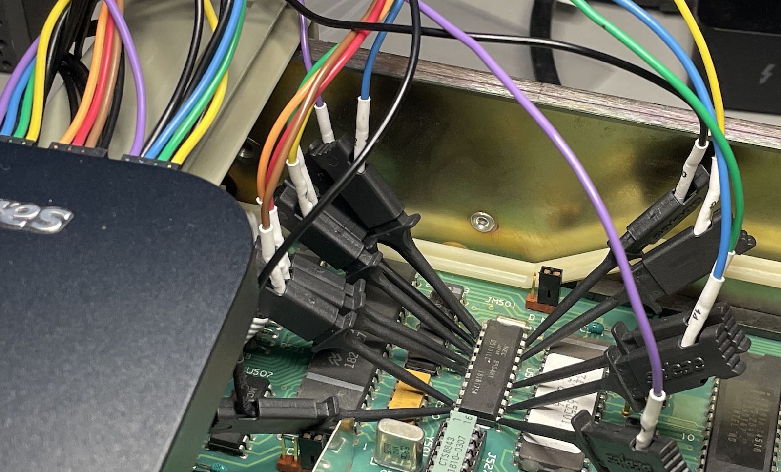
The battery in the 3478A is not socketed but soldered straight on the PCB, with contacts spot welded the plus and the minus terminals.
The schematic and PCB list a 3V battery, but as far as I can tell, all batteries start out higher, with the voltage dropping as the battery charge goes down. In my case, the voltage was at 3.03V.
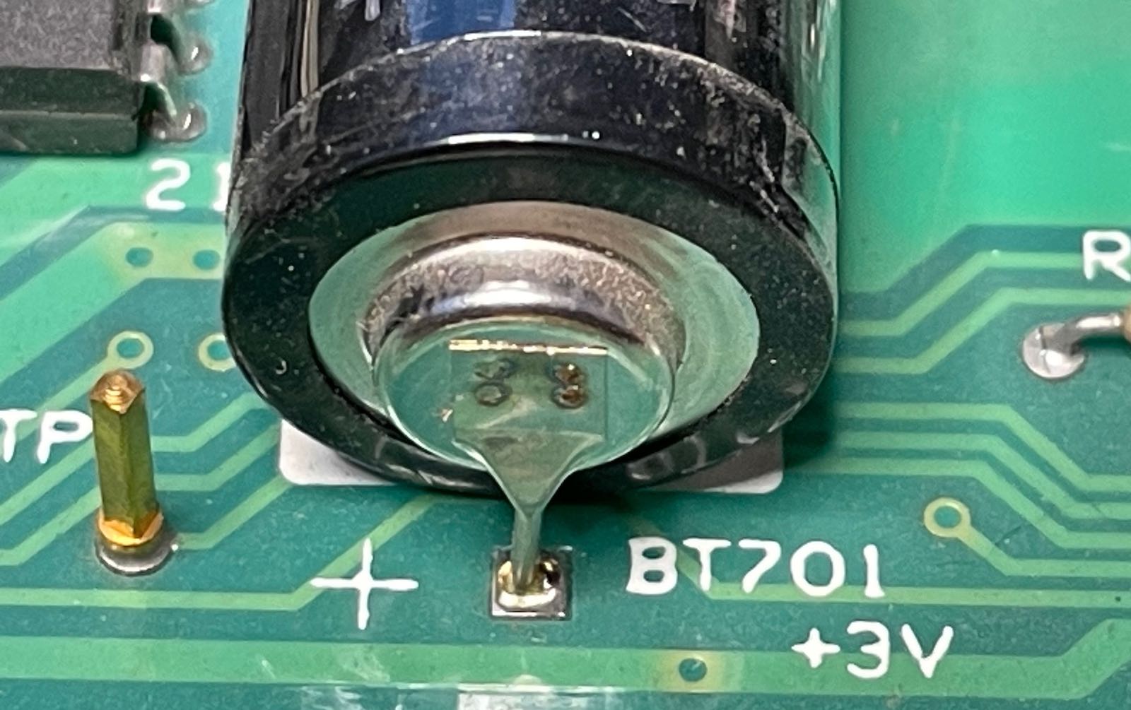
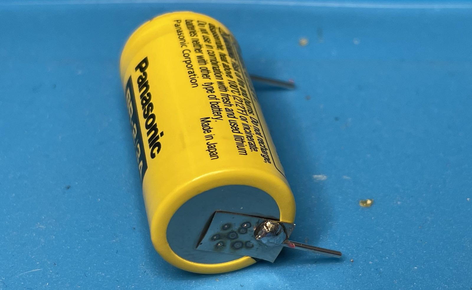
Digikey sells the BR-2/3AE5SPN battery, with spot welded contacts:
An alternative is to use a battery with wires, as in this Youtube video. It has the benefit of being able to wrap the battery in a plastic so that battery leaks won’t destroy the PCB, but then you need a way to fix the battery in place somewhere.
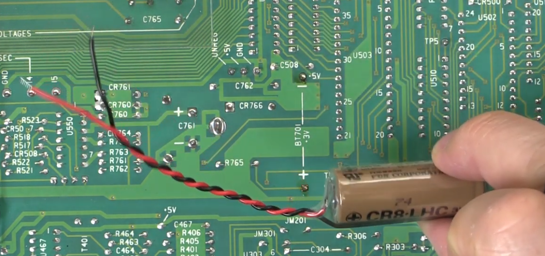
Important! Don’t follow the instructions of that Youtube video about how to connect a temporary battery in parallel: he’s doing it wrong!
I mistakenly ordered the BR-2/3A battery without the through-hole pins. Luckily, I have one of those $40 spot welders and was able to attach the pins myself.
SRAM Power Circuit
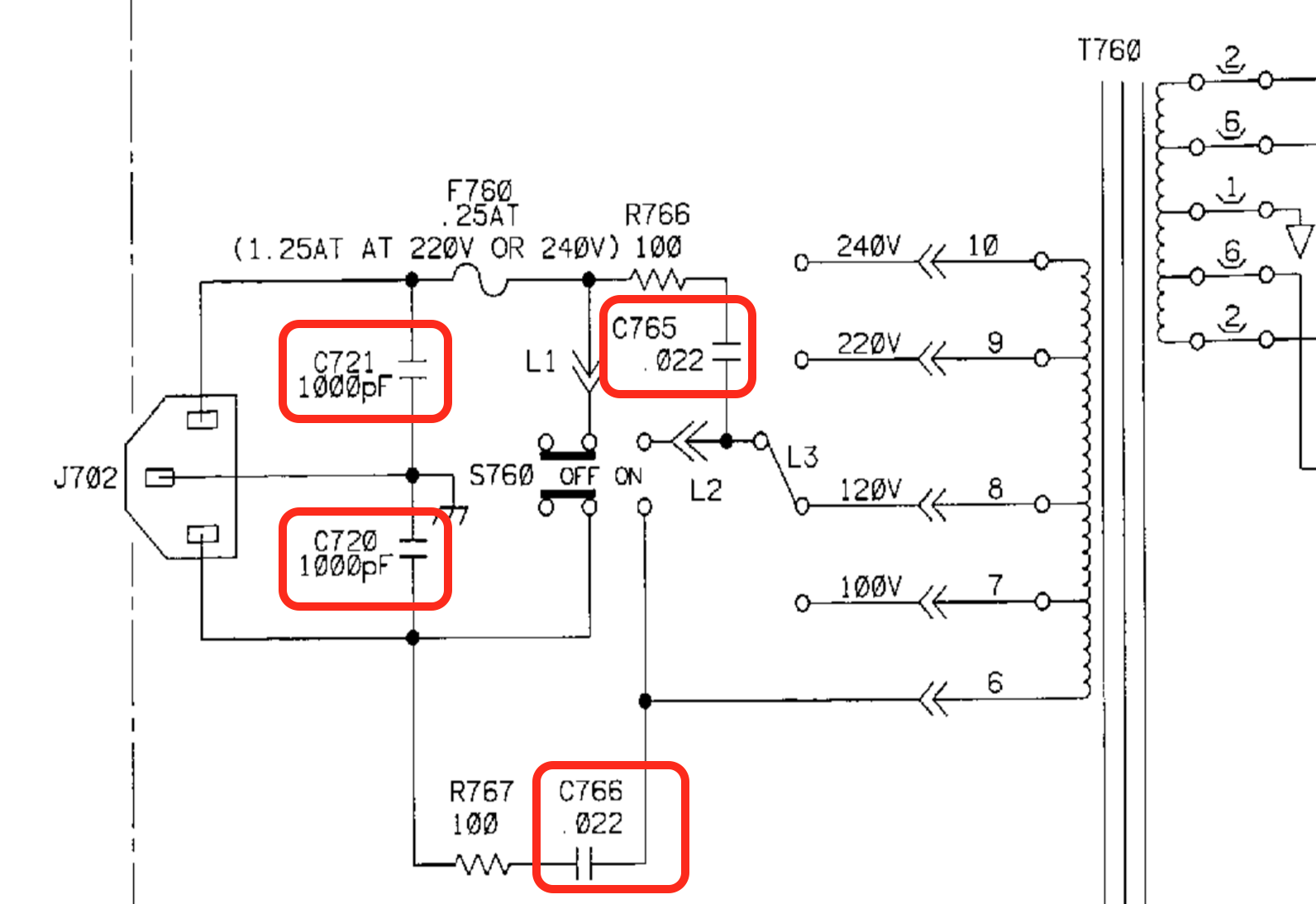
Let’s have a look at the service manual and check out how the SRAM is powered.
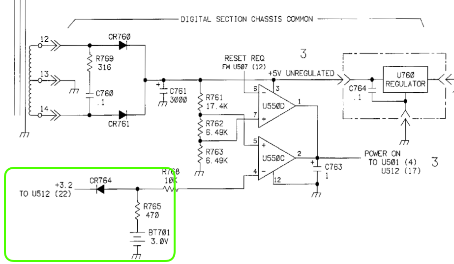
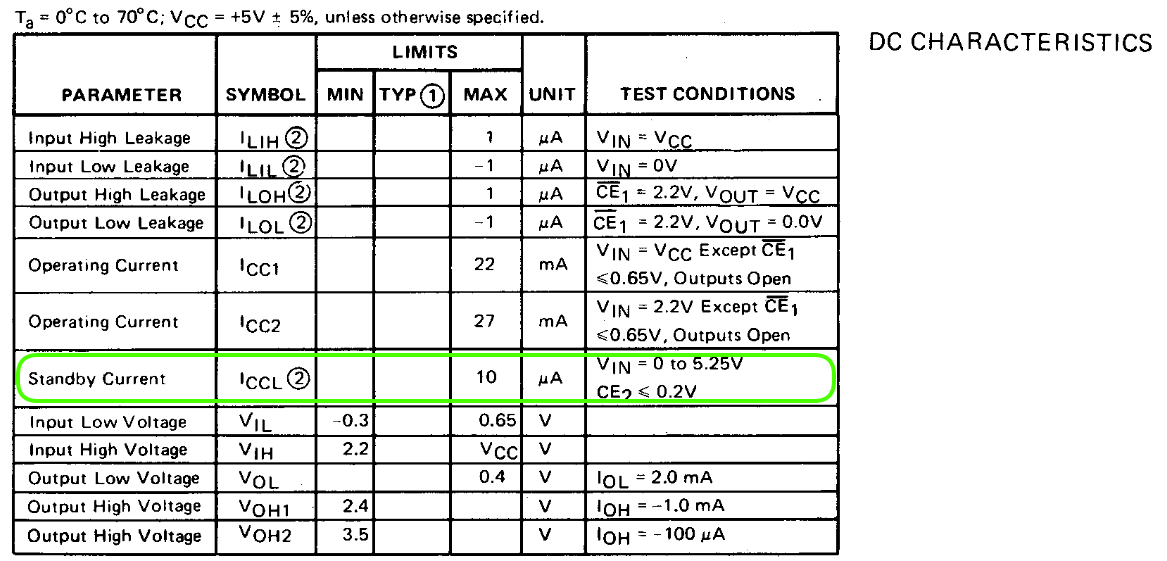
On page 156, marked in green, you can see the battery itself (BT701), a resistor and a diode. I don’t quite understand why you’d put a resistor in series with a battery, but when the main power is switched off, there’s no resistive path to ground, so it shouldn’t matter, especially when the standby current of the SRAM is only 10uA:
The diode is important though: it prevents current from going from the 5V rail to the 3V battery when the main power is switched on.
Meanwhile, on page 154, the SRAM itself is U512. Once again, you can see the power supply area in green.
Unrelated, but in red, you can see how the CAL ENABLE switch forces the R/W pin of the SRAM permanently to R when
the switch is open.
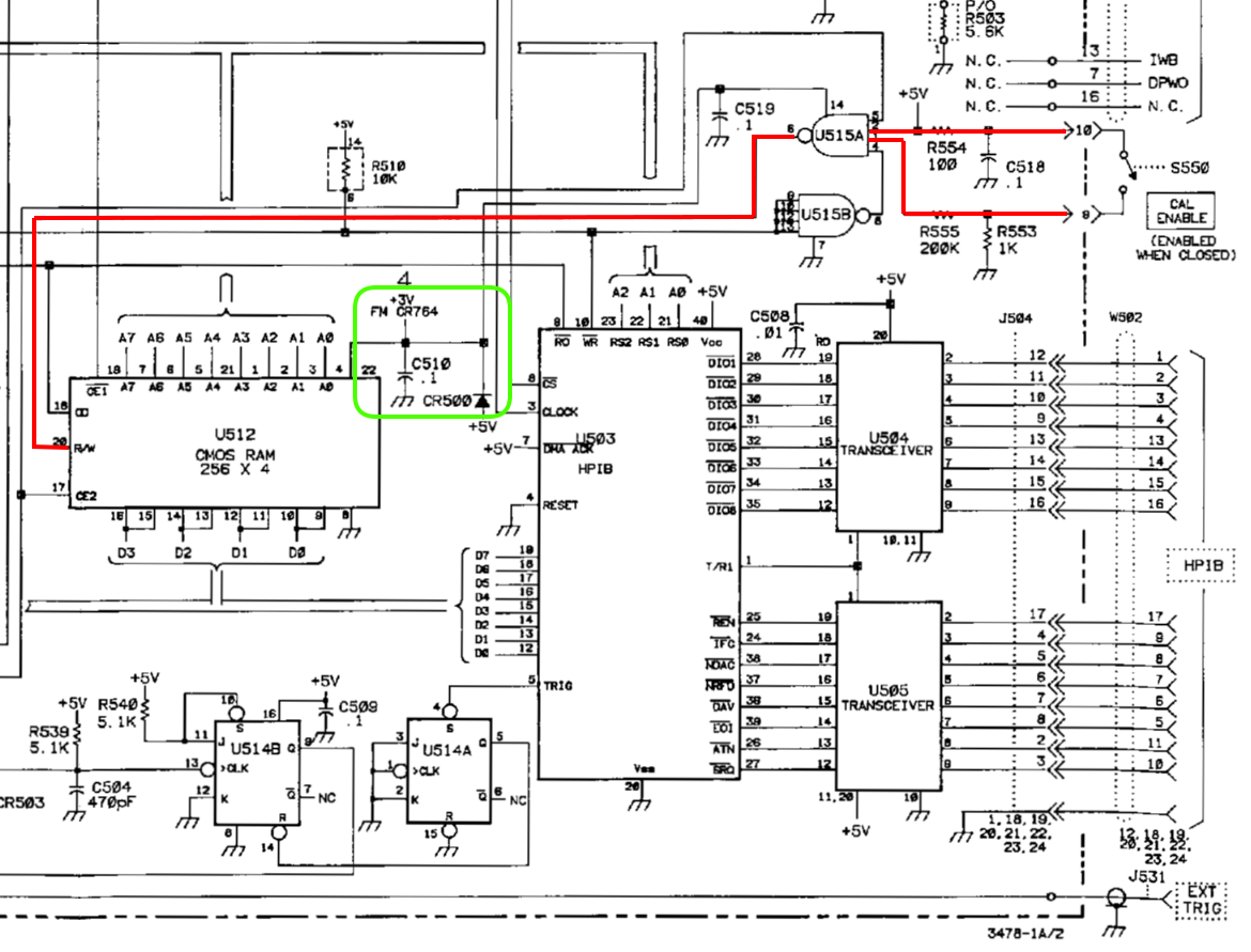
We can see another diode, this time between the SRAM and the +5V supply. This diode prevents current flowing from the 3V battery to 5V power rail when the main power is off.
When you pull everything together, the schematic looks like this:
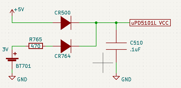
This is all very conventional.
Swapping the Battery
If you want to swap the battery with a new one, these are your options:
-
The obvious way: back up calibration data. Unplug the power cable. Desolder old battery. Solder new battery. Restore calibration data.
Unplug the power cable of the 3478A before soldering!
With his method, you need that GPIB interface to read and write the calibration data.
Or do you?
I went this route and didn’t need to restore the calibration data! I’ve seen similar reports online. I’m speculating that there’s sufficient charge in capacitor C510 to keep the SRAM from losing its contents. After all, there’s really nothing else to discharge that capacitor.
-
The dangerous way: replace the battery while the whole device is switched on.
This way, the 5V power rail stays on as well and the SRAM won’t lose its contents.
This method is dangerous for 2 reasons: you’ll be soldering on a device with active 110V or 220V AC. For me, that reason enough to not consider this option.
Another issue is that the heating tip of almost all soldering irons is connected to ground. When the multimeter is plugged in as well, this could result in a short when you accidentally touch some random contacts. So you have use an iron that isn’t plugged into a regular power socket: there are butane powered irons, or you could use one that’s powered by a USB power bank.
But really, just don’t do it…
-
The intermediate way: use an additional, temporary 3V battery to keep the SRAM powered on.
Unplug the power cable of the 3478A before soldering!
This the way to go if you don’t have a GPIB interface.
Put 2 AA or AAA batteries in a dual battery cage to create an additional 3V, add a third diode, and temporarily(!) solder it to PCB.
The schematic of the updated contraption looks like this:
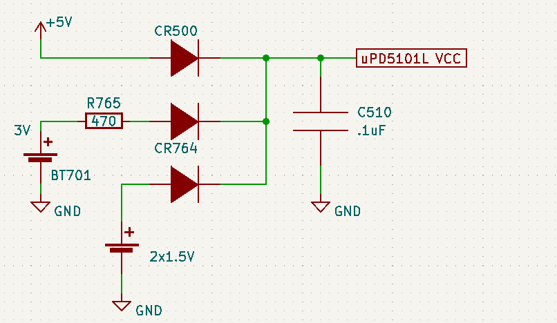
The SRAM only needs 2V for data retention while in standby mode, so any diode with a forward voltage of less than 1V should work. If you don’t have one in your toolbox, just add a few $0.10 1N4148 diodes to your Digikey shopping list.
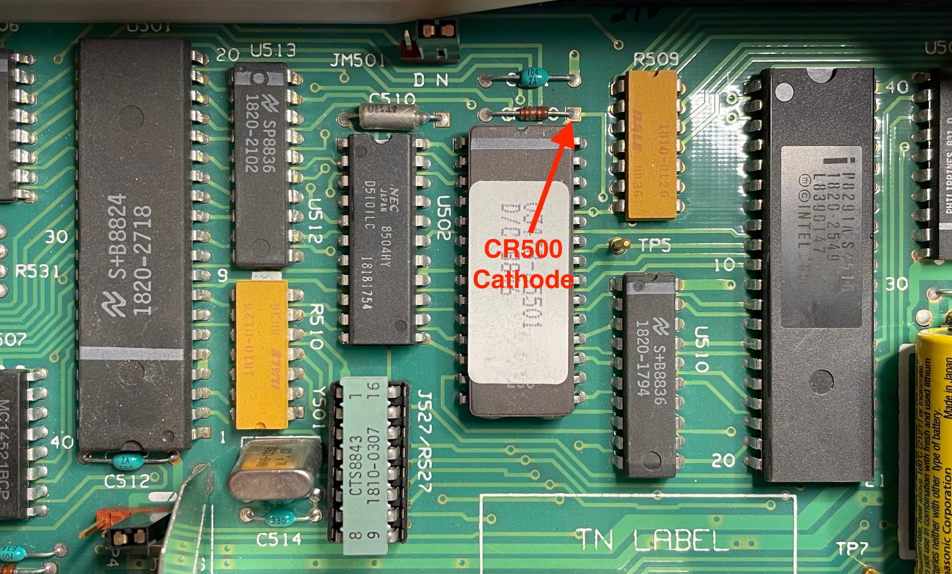
There are plenty of places to solder the ground. The easiest place to solder the cathode of the new diode is at the cathode of CR500:
This blog post by Mr. Modemhead combines the last two methods for redundancy on a similar but-no-quite-the-same HP 3468A multimeter.
References
Info
- EEVblog forum: HP 3478A: How to read/write cal SRAM
- Mr. Modemhead: HP 3468A battery replacement
- Replacing the battery in a HP 3478A Multimeter
Tools
-
HP3478A instrument control software
Windows tool to configure an HP 3478A.
-
The reference implementation for calibration access. DOS only.
-
Python-base instrument control library. I added calibration data backup/restore support to the HP 3478A driver.