Setting Up a Symmetricom SyncServer S200 Network Time Protocol Server
- Introduction
- What was the SyncServer S200 Supposed to be Used For?
- IMPORTANT: Use the Right GPS Antenna!
- The SyncServer S200 Outside and Inside
- Installing the Missing BNC Connectors
- Setting Up a SyncServer S200 from Scratch
- Opening up the SyncServer S200
- The SyncServer File System on the Flash Card
- Cloning the CompactFlash Card
- Reset to Default Settings
- Setting the IP Address
- Accessing the Web Interface
- DNS Configuration
- External NTP Server Configuration
- Testing your NTP server
- A Complicated Power Hungry Clock with a Terrible 10 MHz Output
- Coming Up: Make the S200 Lock to GPS
- References
- Footnotes
Introduction
The Silicon Valley Electronics Flea Market runs every month from March to September and then goes on a hiatus for 6 months, so when the new March episode hits, there is a ton of pent-up demand… and supply: inevitably, some spouse has reached their limit during spring cleaning and wants a few of those boat anchors gone. You do not want to miss the first flea market of the year, and you better come early, think 6:30am, because the good stuff goes fast.
But success is not guaranteed: I saw a broken-but-probably-repairable HP 58503A GPS Time and Frequency Reference getting sold right in front of me for just $40. And while I was able to pick up a very low end HP signal generator and Fluke multimeter for $10, at 8:30am I was on my way back to the car, unsatisfied.
Until that guy and his wife, late arrivals, started unloading stuff from their trunk onto a blanket. There it was, right in front of me, a Stanford Research Systems SR620 universal counter. I tried to haggle on the SR620 but was met with a “You know what you’re doing and what this is worth.” Let’s just say that I paid the listed price which was still a crazy good deal. I even had some cash left in my pocket.
Which is great, because right next to the SR620 sat a pristine looking Symmetricom SyncServer S200 with accessories for the ridiculously low price of $60.
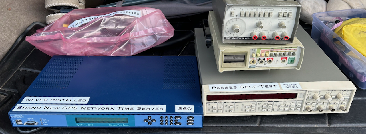
I’ve never left the flea market more excited.
I didn’t really know what a network time server does, but since it said GPS time server, I hoped that it could work as a GPSDO with a 10 MHz reference clock and a 1 pulse-per-second (1PPS) synchronization output. But even if not, I was sure that I’d learn something new, and worst case I’d reuse the beautiful rackmount case for some future project.
Turns out that out of the box a SyncServer S200 can not be used as a GPSDO, but its close sibling, the S250, can do it just fine, and it’s straightforward to do the conversion. A bigger problem was an issue with the GPS module due to the week number rollover (WNRO) problem.
In this and upcoming blog posts, I go through the steps required to bring a mostly useless S200 back to life, how to add the connectors for 10 MHz and 1PPS outputs, which allowed it to do double duty as a GPSDO, and how to convert it into a full S250.
Some of what is described here is based on discussions on EEVblog forum such as this one. I hope you’ll find it useful.
What was the SyncServer S200 Supposed to be Used For?
Symmetricom was acquired by Microsemi and the SyncServer S200 is now obsolete but Microsemi still has a data sheet on their website.
Here’s what it says in the first paragraph:
The SyncServer S200 GPS Network Time Server synchronizes clocks on servers for large or expanding IT enterprises and for the ever-demanding high-bandwidth Next Generation Network. Accurately synchronized clocks are critical for network log file accuracy, security, billing systems, electronic transactions, database integrity, VoIP, and many other essential applications.
There’s a lot more, but one of the key aspects of a time server like this is that it uses the Network Time Protocol (NTP), which…
… is a networking protocol for clock synchronization between computer systems over packet-switched, variable-latency data networks.
The SyncServer S200 is a stratum 1 level device. The stratum level indicates the hierarchical distance to an authorative atomic reference clock. While it does not act as a stratum 0 oracle of truth, it can derive the time directly from a stratum 0 device, in this case the GPS system.
When the GPS signal disappears, a SyncServer can fall back to stratum 2 mode if it can retrieve the time from other stratum 1 devices (e.g. other NTP-capable time servers on the network) or it can switch to a hold-over mode where it lets an internal oscillator run untethered, without being locked to the GPS system.
The S200 has 3 oscillator options:
- a TCXO with a drift of 21ms per day
- an OCXO with a drift of 1ms per day
- a rubidium atomic clock with drift of only 25us per day
Mine has the OCXO option.
It’s clear that the primary use case of the S200 is not to act as a lab clock or frequency reference, but something that belongs in a router cabinet.
IMPORTANT: Use the Right GPS Antenna!
Before continuing, let’s interrupt with a short but important service message:
GPS antennas have active elements that amplify the received signal right at the point of reception before sending it down the cable to the GPS unit. Most antennas need 3.3V or 5V that is supplied through the GPS antenna connector, but Symmetricom S200 supplies 12V!
Make sure you are using a 12V GPS antenna!
Check out my earlier blog post for more information.
The SyncServer S200 Outside and Inside
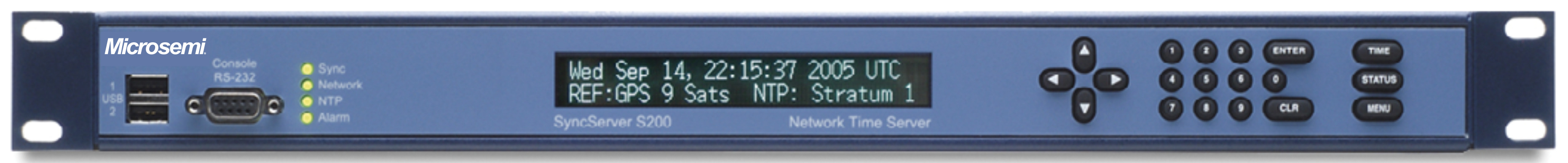
The front panel has 2 USB type-A ports, an RS-232 console interface, a vacuum fluorescent display (VFD), and a bunch of buttons.
 Click to enlarge
VFDs have a tendency to degrade over time, but mine is in perfect shape.
 Click to enlarge
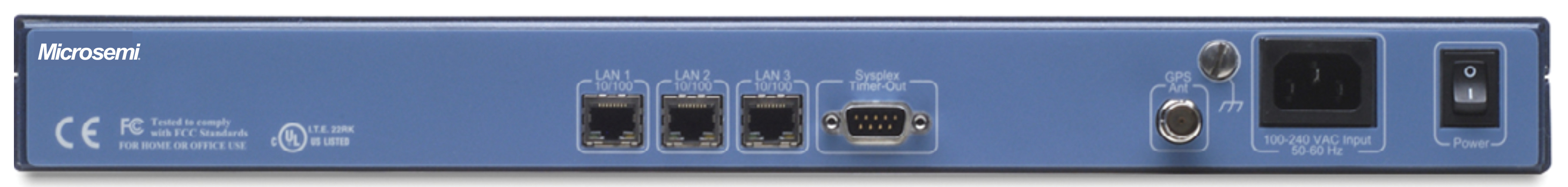
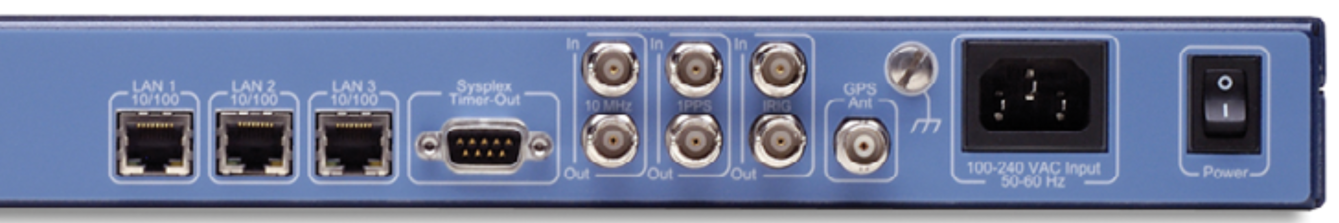
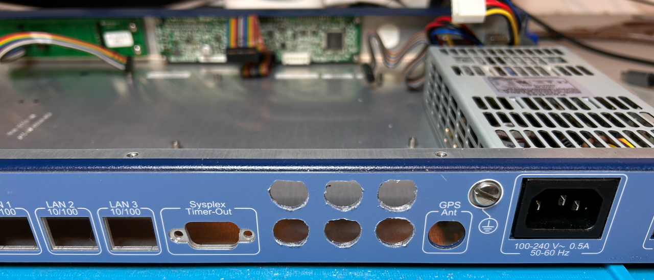
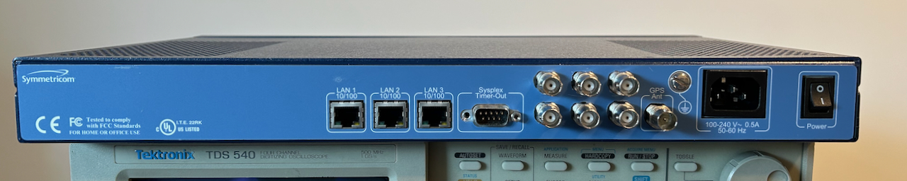
In the back, we can see a power switch for the 100-240VAC mains voltage1, a BNC connector for the GPS antenna, a Sysplex Timer-Out interface, and 3 LAN ports.
Let’s see what’s inside:
 Click to enlarge
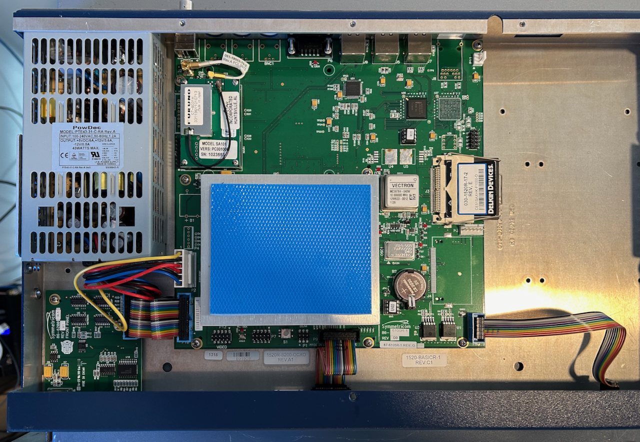
Under the heatshink with the blue heat transfer pad sits an off-the-shelf embedded
PC motherboard with a 500 MHz AMD Geode x86 CPU with 256MB of DRAM. Not all SyncServer S200
models use the same motherboard, some of them have a VIA Eden ESP 400 MHz processor. Using the
front panel RS-232 serial port, I recorded this boot.log file that contains
some low level details of the system.
The PC is running MontaVista Linux,
a commercial Linux distribution for embedded devices.
At the bottom left sits a little PCB for the USB and RS-232 ports. There are also two cables for the VFD and the buttons.
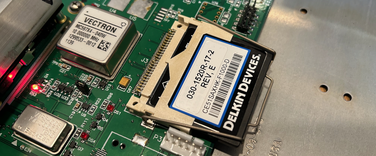
On the right side of the main PCB we can see a Vectron OCXO, the same brand as the huge OCXO that you can find in the GT300 frequency standard of my home lab. It creates the 10 MHz stable clock that’s used for time keeping. A 512MB CompactFlash card contains the operating system. There’s still plenty of room for a Rubidium atomic clock module. It should be possible to upgrade my S200 with a Rubidium standard, but I didn’t try that.
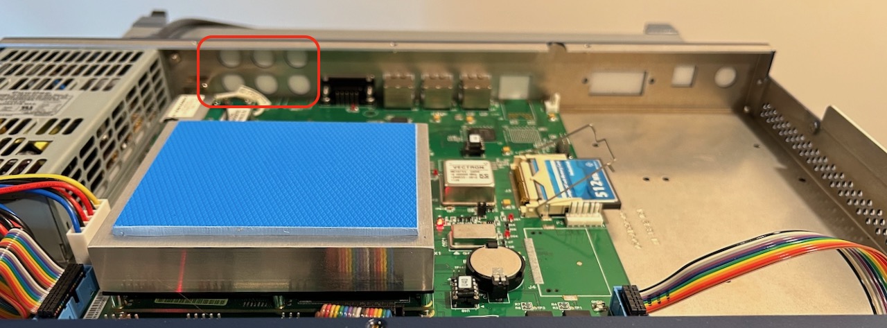
At the top left sits a Furuno GT-8031 GPS module that is compatible with Motorola OnCore M12 modules. There are a bunch of connectors, and, very important, 3 unpopulated connector footprints.
When looking at it from a different angle, we can also see 6 covered up holes that line up with those 3 unpopulated footprints:
 Click to enlarge
Let’s cut to the chase and show the backside of the next model in the SyncServer product line, the S250:
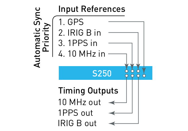
Those 6 holes holes are used for the input and output for the following 3 signals:
- 10 MHz
- 1PPS
- IRIG
We are primarily interested in the 10 MHz and 1PPS outputs, of course.
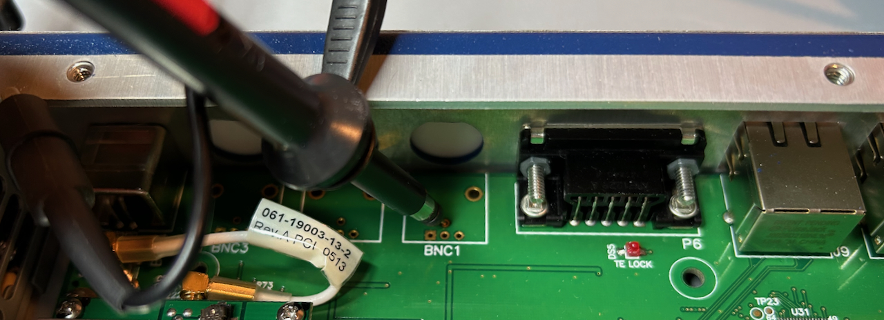
The BNC connectors may be unpopulated, but the driving circuit is not. When you probe the hole for the 10 MHz output, you get this sorry excuse of sine wave:

There’s also a 50% duty cycle 1PPS signal present on the other BNC footprint.
Installing the Missing BNC Connectors
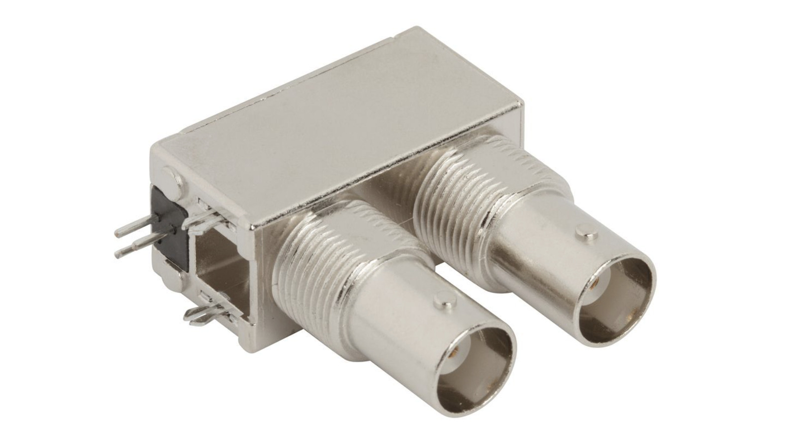
The first step is to install the missing BNC connectors. They are are expensive Amphenol RF 031-6577. I got 3 of them for $17.23 a piece from Mouser. Chances are that you’ll never use the IRIG port, so you can make do with only 2 connectors to save yourself some money.
You need to remove the whole main PCB from the case, which is a matter of removing all the screws and some easy to disconnect cables and then taking it out. The PCB rests on a bunch of spacers for the screws. When you slide the PCB out, be very careful to not scrape the bottom of the PCB against these spacers!
Next up is opening up the covered holes. The plastic that covers these holes is very sturdy. It took quite a bit of time to open them up with a box cutter.
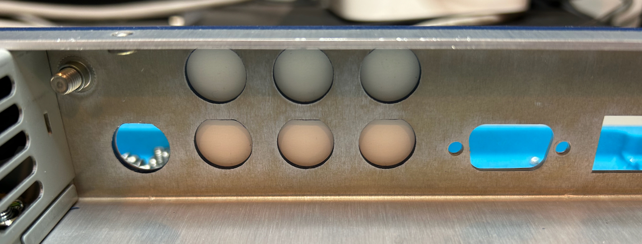
The holes are not perfectly round: they have a flat section at the top. Open up the holes as much as possible because the BNC connectors will have to go through them during reassembly and you want this to go smoothly without putting strain on the PCB.
The end result isn’t commercial product quality, but it’s good enough for something that will stay hidden at the back of the instrument.
Installing the BNC connectors is easy: plug them in and solder them down…
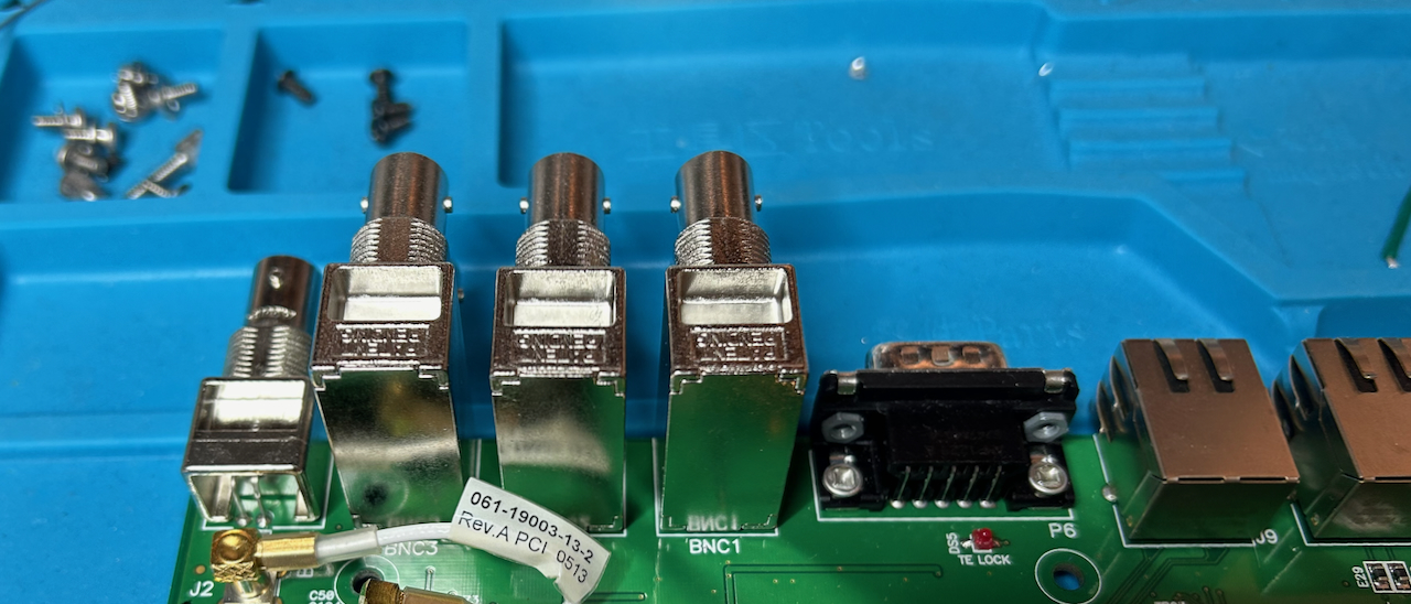
Due to the imperfectly cut BNC holes, installing the main PCB back into the chassis will be harder than removing it, so, again, be careful about those spacers at the bottom of the case to prevent damaging the PCB!
The end result looks clean enough:
Setting Up a SyncServer S200 from Scratch
My first goal was to set up the SyncServer so that it’d be synchronized to the GPS time and display the right time on the display. That should be a pretty simple thing to do, but it took many hours before I got there. There were 3 reasons for that:
- due to the WNRO issue, the SyncServer didn’t want to lock onto the GPS time.
- the default IP addresses for the Symmetricom NTP servers aren’t operational anymore. But that wasn’t clear in the status screen.
- when I tried alternative NTP servers, they couldn’t be found because I hadn’t configured any DNS servers.
- configuring the SyncServer to get its IP using DHCP is a bit of nightmare.
My focus was first on the GPS and then the NTP part, but here I’ll do things in the opposite order so that you get somehwere without the kind of hardware hacking that I ended up doing.
Opening up the SyncServer S200
Just remove the 4 black screws at the top of the case and lift the top cover.
I wish other equipment was just as easy.
The SyncServer File System on the Flash Card
The S200 uses a 512MB flash card to store the OS. I wanted to have a look at the contents and make a copy as well so that I wouldn’t have to worry about making crucial mistakes.
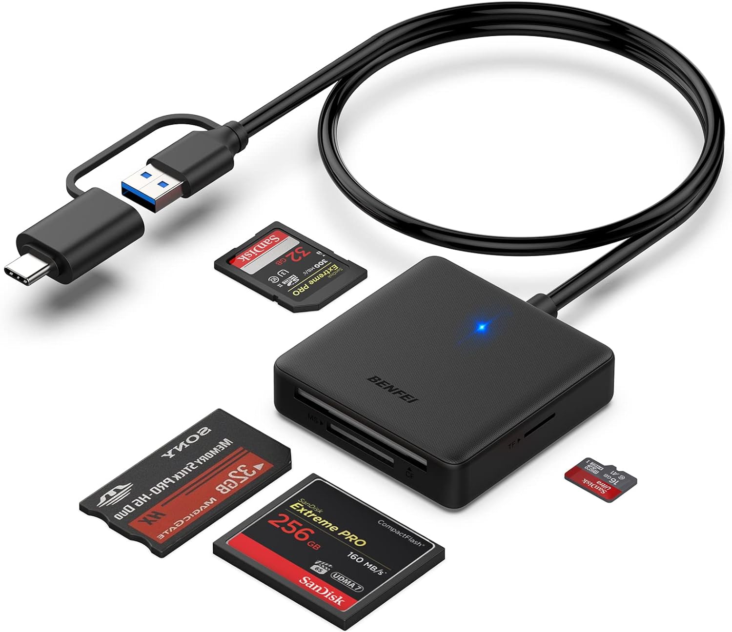
I bought a compact flash card reader on Amazon for $8.
After plugging in the drive:
$ df
/dev/sdb7          97854         2     92720   1% /media/tom/_tmparea
/dev/sdb2           8571       442      7683   6% /media/tom/_persist
/dev/sdb5         173489     69985     94256  43% /media/tom/_fsroot1
/dev/sdb6         173489     69986     94255  43% /media/tom/_fsroot2
In my case, the drive is mounted on /dev/sdb but this will probably be different for you.
The flash card has 4 different partitions. I did some digging to understand how the system works.
OS partititions _fsroot1 and _fsroot2
The _fsroot1 and _fsroot2 partitions contain copies of the OS itself.
Before making any changes on my system, I checked the chronosver file that resides in the
root directory of each partition:
cat _fsroot1/chronosver
#
# SyncServer version
#
# $Date: 2010-12-08-093436 $
#
# The format is Major.Minor
Version=1.26

#
# For internal identification
#
Revision=$ProjectRevision: Last Checkpoint: 1.666.10.3420934 $
and:
cat _fsroot2/chronosver
#
# SyncServer version
#
# $Date: 2010-12-08-093436 $
#
# The format is Major.Minor
Version=1.26

#
# For internal identification
#
Revision=$ProjectRevision: Last Checkpoint: 1.666.10.3420934 $
The versions are identical and indicate that version 1.26 of the system
is installed. Later versions 1.30 and 1.36 are available. When you install
those, you’ll see that only 1 of the partitions gets updated, so what’s happening
is that one _fsroot partition gets updated and the system boots the newest version.
Except when doing an OS upgrade, the _fsroot partitions on the flash card are always
mounted as read-only, even when making system configuration changes.
Persistent configuration partition _persists
The _persist partition contains a tar file of the /var and /etc directories
with configuration data. When you make changes through the web interface, the changes
end up here.
ll _persist/
total 445
drwxr-xr-x  2 root root   1024 Jan  2  2006 ./
drwxr-x---+ 7 root root   4096 Jun 23 17:40 ../
-rw-r--r--  1 root root   2059 Dec  8  2010 downgradelist
-rw-r--r--  1 root root     50 Jan  1  2006 persist-1.2.md5
-rw-r--r--  1 root root 440320 Jan  1  2006 persist-1.2.tar
-rw-r--r--  1 root root   2062 Dec  8  2010 upgradelist
The _fsroot partitions contain /etc and /var directories as well, but when
mounted on the real system, the contents of these directories come from the tar file.
However, when you reset the system back to default values, it restores back to the values
in the _fsroot partition.
System upgrade staging area _tmparea
The _tmparea partition is used as a staging area when upgrading the system.
When you use the web interface to upload a new version, the file gets stored here before
one of the _fsroot directories gets overwritten.
Cloning the CompactFlash Card
You don’t really need a second flash card: a full disk copy of the contents of the original card can be saved to your PC and restored from there, but I found it useful to have a second one to swap back and forth between different flash cards while experimenting.
There is a plenty chatter in the EEVBlog forum about which type of flash card does or doesn’t work. It must a CompactFlash card with fixed disk PIO instead of removable DMA support and it’s also good to use one that is an industrial type because those have long-life SLC-type flash memory chips that allow more read-write operations and a higher temperature range, but that’s where the concensus ends. Some people aren’t able even make a 512MB card work. Others claim that their 512MB card worked, but that larger capacity ones didn’t.
I bought this 512MB card and it worked fine, and this 1GB one worked fine too. I ran into none of the issues that some other people seem to have. I wonder if it has to do with the kind of embedded PC motherboard that my system is using: remember that there are different versions out there.
Windows people should use something like HDD Raw Copy Tool to make a copy, but it’s just as easy to use the standard Linux disk utilities.
Copy the whole flash card contents to a file on your Linux machine like this:
$ sudo dd if=/dev/sdb of=flash_contents_orig.img bs=1M
[sudo] password for tom:
488+1 records in
488+1 records out
512483328 bytes (512 MB, 489 MiB) copied, 40.6726 s, 12.6 MB/s
If you have a second flash card, copying the original contents to that one works the same way:
$ sudo dd if=flash_contents_orig.img of=/dev/sdb bs=1M && sync
488+1 records in
488+1 records out
512483328 bytes (512 MB, 489 MiB) copied, 0.143977 s, 3.6 GB/s
Notice the sync command at the end: if you don’t do that, you’ll get your
command line back right away while the copy operation is going on in the background.
I didn’t want to accidentally unplug the thing before it was done.
Unmount the drive after copying:
sudo unmount /dev/sdb
You’re all set now to plug the old or the new CF card back into the S200.
Reset to Default Settings
Chances are that your SyncServer was used before and that it didn’t come in its default state. That can be a problem, for example when the passwords are different than the default one.
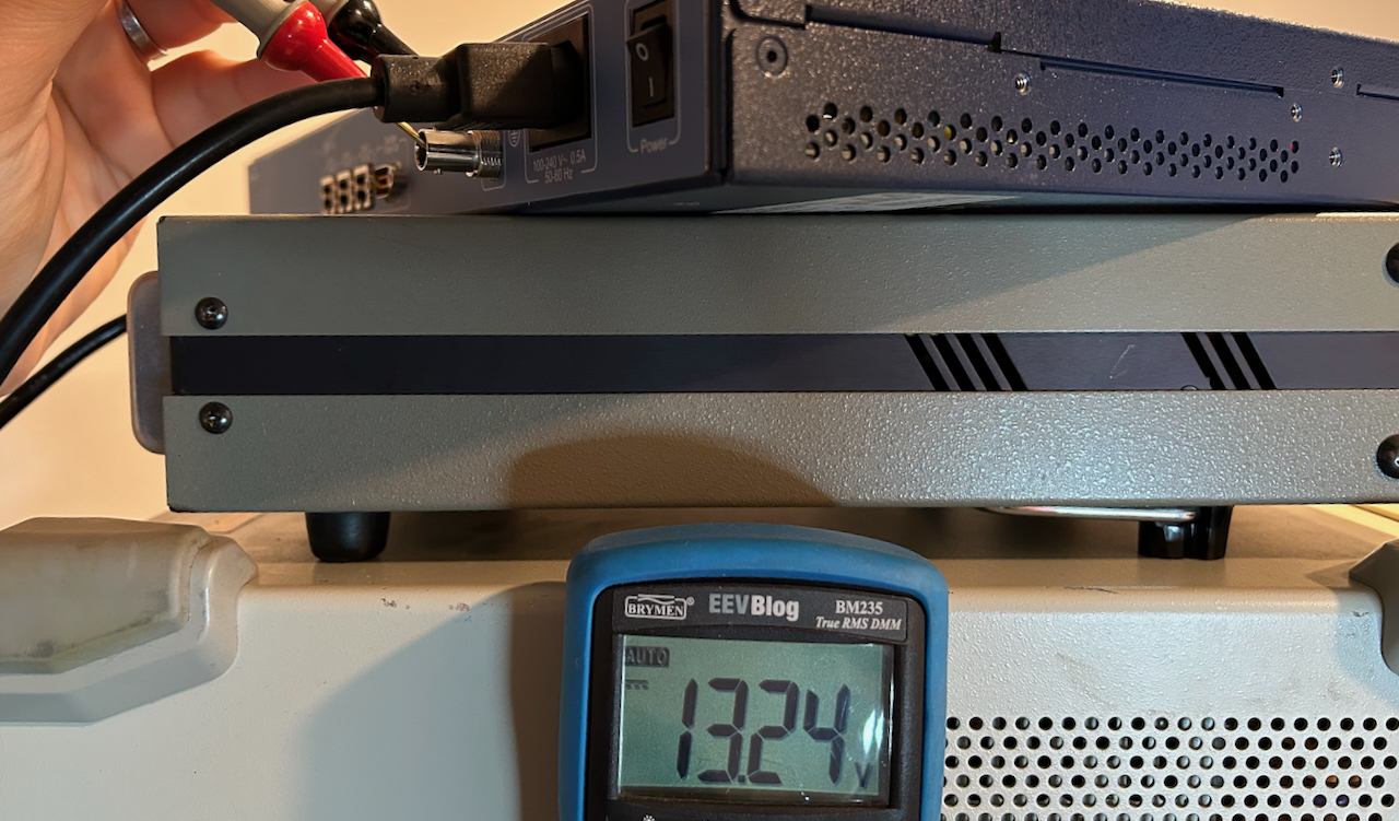
The procedure to reset the device back to factory settings is described on page 120 of the user manual. After opening the device, set jumper JP4 on the motherboard. It’s located at the bottom right of the motherboard, next the CR2032 lithium battery.
The jumper pins have a smaller than usual 0.1” pitch so you can’t use a standard jumper. I used logic analyzer grabbers to make the connection:
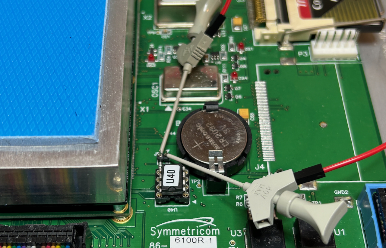
Install the jumper connection, power up the device, wait for 100 seconds, power the device back off, and remove the connection. When powered up, there won’t be any messages or visual indications to tell you that defaults have been restored, you just have to wait long enough.
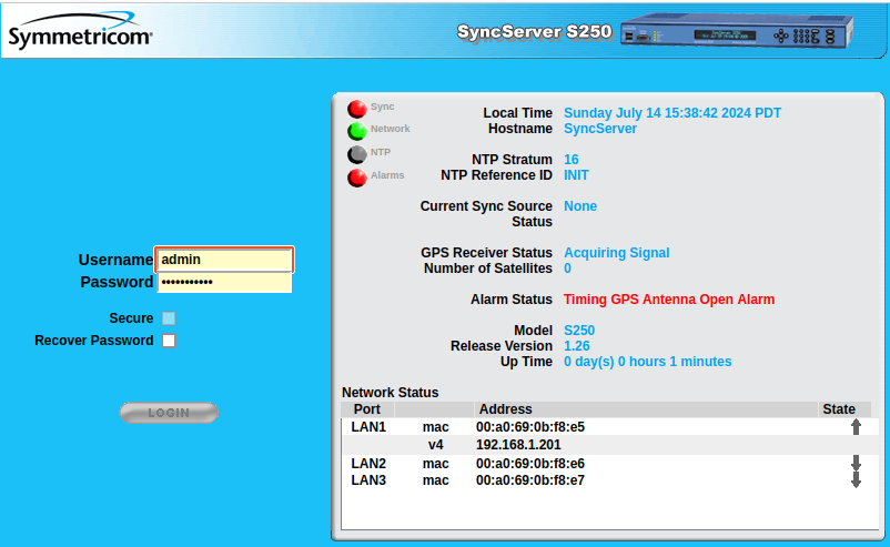
Setting the IP Address
Configuration of the SyncServer happens through a web interface, so the next step is to setup a network connection. The user guide recommends assigning static IP addresses instead of DHCP because NTP associations and authentication may rely on static network addresses. This was good advice because I was never able to get the SyncServer to work with DHCP…
While there are 3 LAN ports, only port 1 can be used for web management. You’ll need to set the IP address, the gateway address mask, and the gateway addresses through the front panel. I used the following settings, because that’s how my home is configured:
- IP address: 192.168.1.201
- Gateway address mask: 255.255.255.0
- Gateway IP address: 192.168.1.1
Values for your network may be different.
If your home network uses DHCP for all other devices, it’s best to tell your router to exclude the chosen static IP address from the list of dynamically assignable IP addresses. I explain in my HP 1670G blog post how to this with an Asus router.
Once LAN port 1 has been enabled an configured, plug in a network cable. The network LED on the front panel of the device should turn green.
If all went well, you can now ping the SyncServer from your host machine:
ping 192.168.1.201
PING 192.168.1.201 (192.168.1.201): 56 data bytes
64 bytes from 192.168.1.201: icmp_seq=0 ttl=64 time=2.172 ms
64 bytes from 192.168.1.201: icmp_seq=1 ttl=64 time=3.221 ms
64 bytes from 192.168.1.201: icmp_seq=2 ttl=64 time=2.195 ms
...
Some DHCP notes
If against the general advice, you still decide to use DHCP, here are some notes:
- when you switch LAN port 1 to DHCP through the front panel for initial configuration, the web interface won’t work. Your first configuration round must happen with a static IP address. It’s during that round that you must tell the device that further web configuration is allowed over a DHCP enabled LAN port 1.
- when DHCP is enabled and a network cable is not plugged in when powering up, the SyncServer bootup time increase by several minutes. This is because the SyncServer is waiting for IP address assignment until a certain time-out value is reached.
- DHCP IP address assignment only happens at initial bootup. If you plug in the network cable when the device is already up and running, no IP address will be assigned.
Accessing the Web Interface
Going forward, most web interface screenshot will show a header that says “SyncServer S250” instead of “S200”. Modding the device to an S250 is something that will be discussed in a future blog post.
With your browser, you should now be able to access the web interface by going to IP address that you assigned:
When using default settings, the following credentials are active:
- Username: admin
- Password: symmetricom
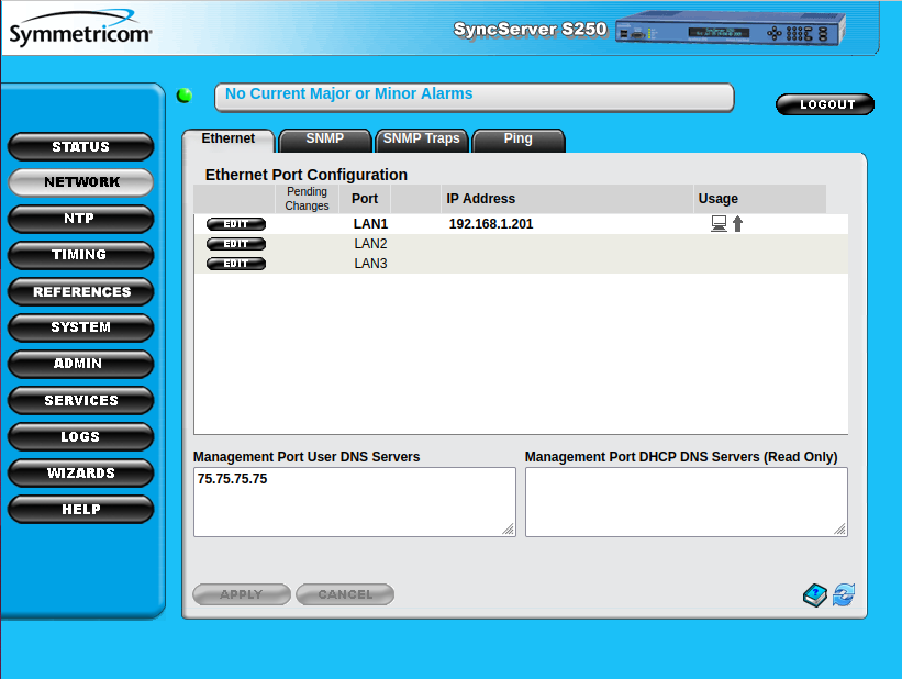
DNS Configuration
Now is the time to assign DNS servers. This step is crucial if you want your SyncServer to work with external NTP servers, since most of them want you to use a hostname instead of an IP address.
Using the web interface, go to “NETWORK” and then the “Ethernet” tab, and then “Add a DNS Server”. I’m using Comcast/Xfinity, which has a DNS server at address 75.75.75.75, so that what’s I used. You’ll need to find the appropriate DNS server for your case, or you can use Google’s Public DNS service at address 8.8.8.8.
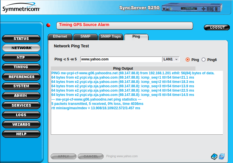
If you set up the DNS server correctly, you should now be able to ping public Internet servers with the “Ping” tab. For the last 35 years, I’ve used “www.yahoo.com” as my ping testing address.
External NTP Server Configuration
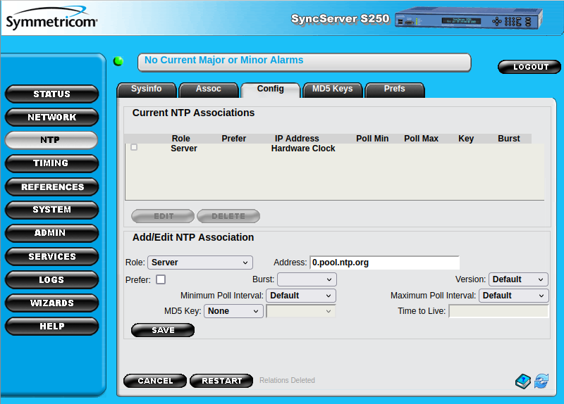
The default settings of my SyncServer make it use static IP addresses 69.25.96.11, 69.25.96.12, and 69.25.96.14 for external NTP requests. Symmetricom used to have NTP servers there, but they are not operational anymore.
You must replace these static IP addresses by other NTP servers. A popular option is ntp.org which offers a free NTP server service. Another alternative are the NTP servers from NIST, the National Institute for Standards and Technology. Or do like I did, and use both!
For ntp.org, use the following addresses: 0.pool.ntp.org, 1.pool.ntp.org, 2.pool.ntp.org,
or 0.us.pool.ntp.org, 1.us.pool.ntp.org, 2.us.pool.ntp.org if you want to force
using a server that is located in the US. For NIST, I used time.nist.gov.
Here is how you fill in the panel to add a server:
And here’s how it looks like after all servers were added:
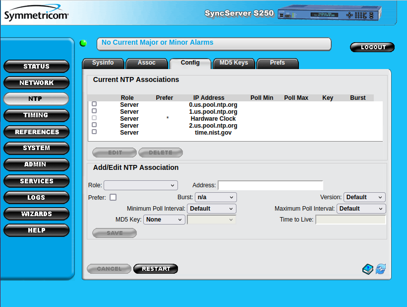
Click “Restart” when all servers have been added, and check out “NTP - Sysinfo” to verify that the SyncServer can successfully talk to the external servers:
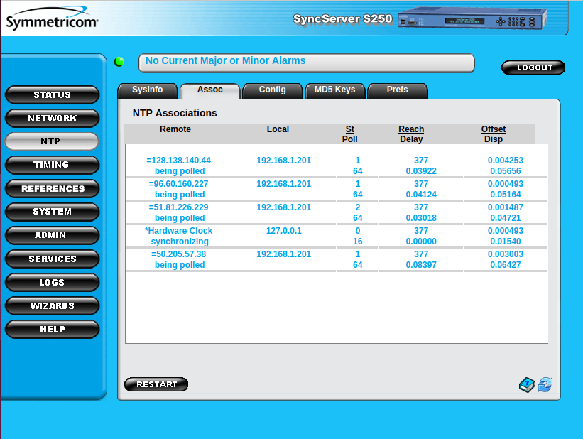
The “St/Poll” columns shows the stratum level and polling time of the servers. In the example above, 4 NTP servers with stratum levels 1 and 2 are being polled. The stratum level will vary because NTP.org rotates through a pool of servers with different levels.
If there’s a configuration issue, you’ll see a stratum level of 16.
Testing your NTP server
After setting up the external NTP servers, your SyncServer can now itself be used as an NTP server.
Using Linux, you can query the date from the SyncServer with the ntpdate tool as follows:
ntpdate -q 192.168.1.201
server 192.168.1.201, stratum 16, offset -0.019111, delay 0.02856
 4 Jun 23:20:32 ntpdate[230482]: no server suitable for synchronization found
Initially, the SyncServer may report itself as an unsynchronized stratum 16 device because NTP server synchronization can take a bit of time, but after around 15 minutes, you’ll get this:
ntpdate -q 192.168.1.201
server 192.168.1.201, stratum 2, offset -0.034768, delay 0.02989
 4 Jun 23:23:21 ntpdate[230491]: adjust time server 192.168.1.201 offset -0.034768 sec
The Sync status LED and web page indicator are now be yellow instead of red: you now have something that should be good enough for time serving needs that don’t require nano-second level accuracy.
Don’t worry about the NTP LED not being constanstly green: it only lights up when the SyncServer polls the external server and that only happens every some many seconds.
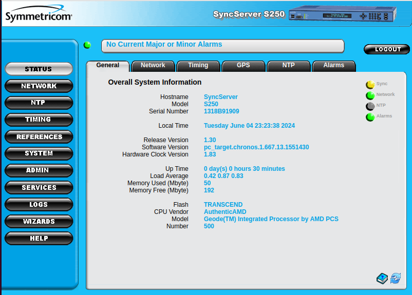
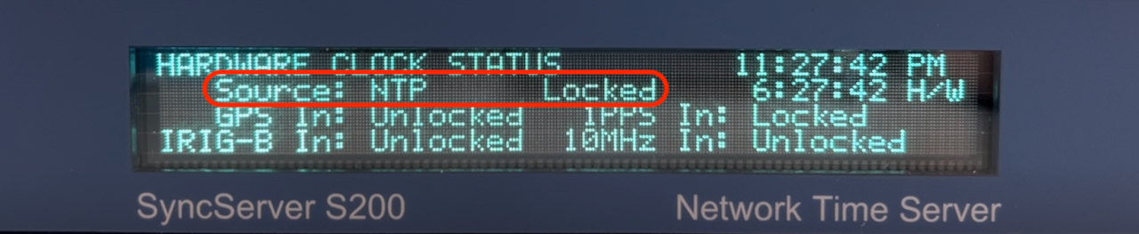
On the front panel and on web interface under “STATUS -> Timing”, you’ll see that the current sync source is NTP and that the hardware clock status is “Locked”.
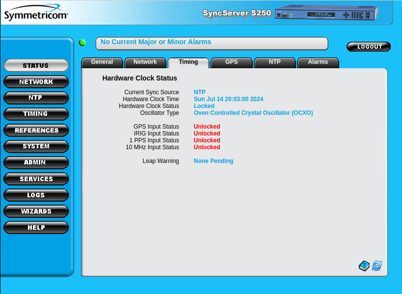
On a S200 you will only see the “GPS Input Status - Unlocked”, there won’t be any IRIG, 1 PPS or 10 MHz input status. Those are S250 features that will be unlocked in a later blog post.
A Complicated Power Hungry Clock with a Terrible 10 MHz Output
All that’s left now to display the correct local time is to set the right time zone. You can do this under “Timing” -> “Time Zone”.
Once you’ve done that, you can use your SyncServer as a slightly overcomplicated living room clock:
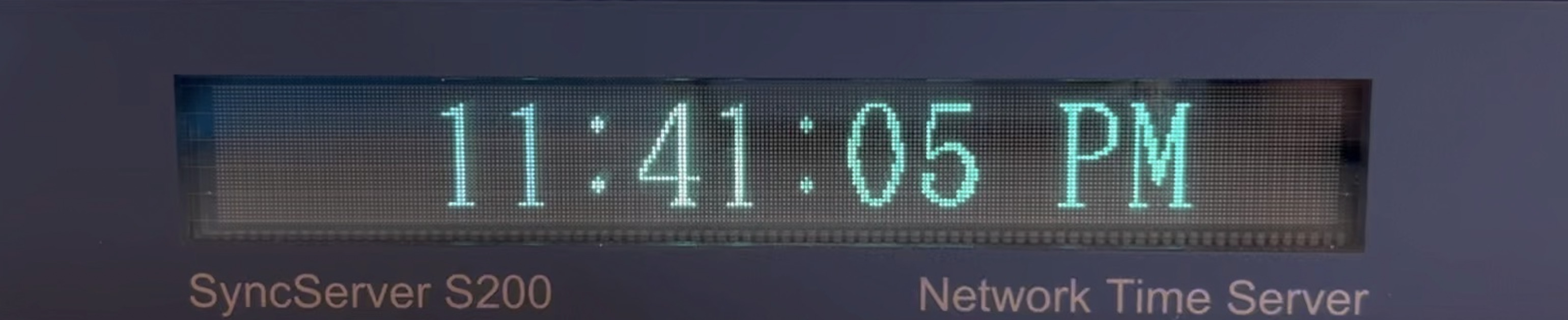
It’s power hungry too: mine pulls roughly 19W from the power socket.
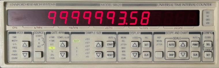
But what about the 10 MHz output? After booting up the S200 when the device is not yet locked to NTP, the Vector OCXO is free-running with a frequency of 9,999,993 Hz, an error of 7Hz2 which makes it unusable for the lab.
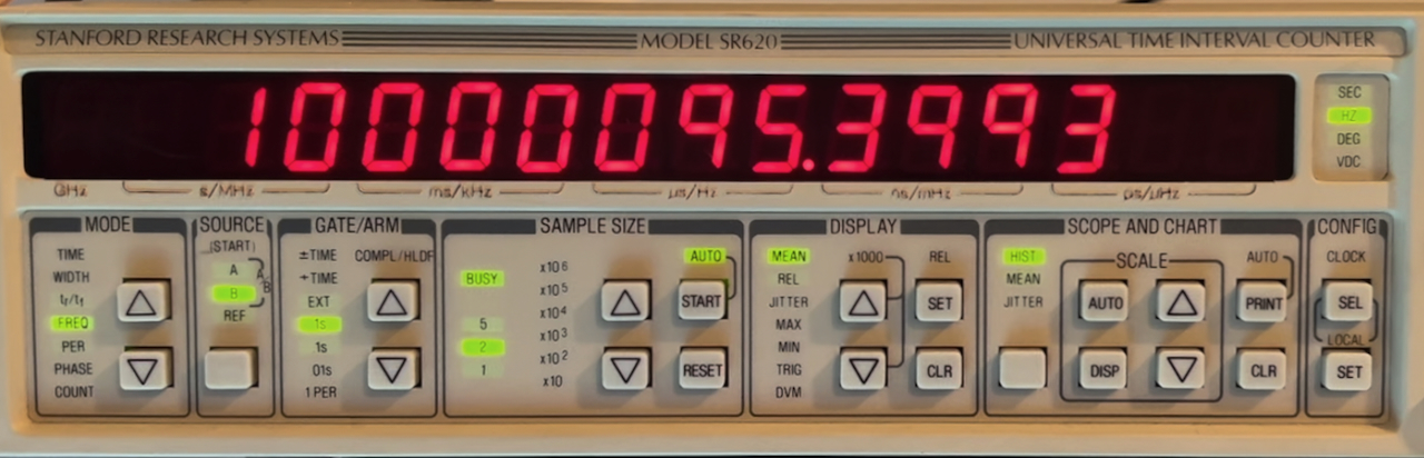
One would expect this error number to go down when the device is locked to NTP, a bad time reference is better than no reference at all, but that’s not the case: as soon as the device locked to NTP, the 10 MHz output locked at 10,000,095 Hz. The error increased with an order of magnitude!
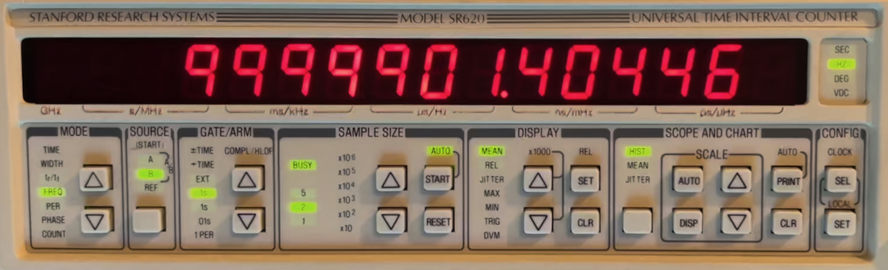
However, since NTP is part of stratum hierarchy, the time should average out to 10 MHz, and indeed, the behavior was bimodal: after around 20 minutes, the 10 MHz output frequency switches to 9,999,001 Hz, which doesn’t quite average to 10 MHz, but that’s because the frequency counter was connected to a non-disciplined reference clock.
For the SyncServer to be usable as a lab timing reference, it clearly needs that GPS input.
It will also be interesting to check the hold-over behavior of the OCXO after it was first locked to the GPS system.
Coming Up: Make the S200 Lock to GPS
In the next blog post, I’ll describe how I was able to make the S200 lock at GPS satellites which makes it a stratum 1 device. This took a lot of work and designing an interposer PCB to work around the GPS WNRO issue. Stay tuned!