Repairing an HP 5370A Time Interval Counter
- Introduction
- Inside the HP 5370A
- High Stability Reference Clock with an HP 10811-60111 OCXO
- RIFA Capacitors in the Corcom F2058 Power Entry Module?
- 15V Rail Issues
- Power Suppy Architecture
- Fault Isolation - It’s the Reference Frequency Buffer PCB!
- The Reference Frequency Buffer Board
- Fixing the Internal Reference Clock
- Fixing the External Reference Clock
- Future work
- References
- Footnotes
Introduction
I bought an HP 5370A time interval counter at the Silicon Valley Electronics Flea Market for a cheap $40.
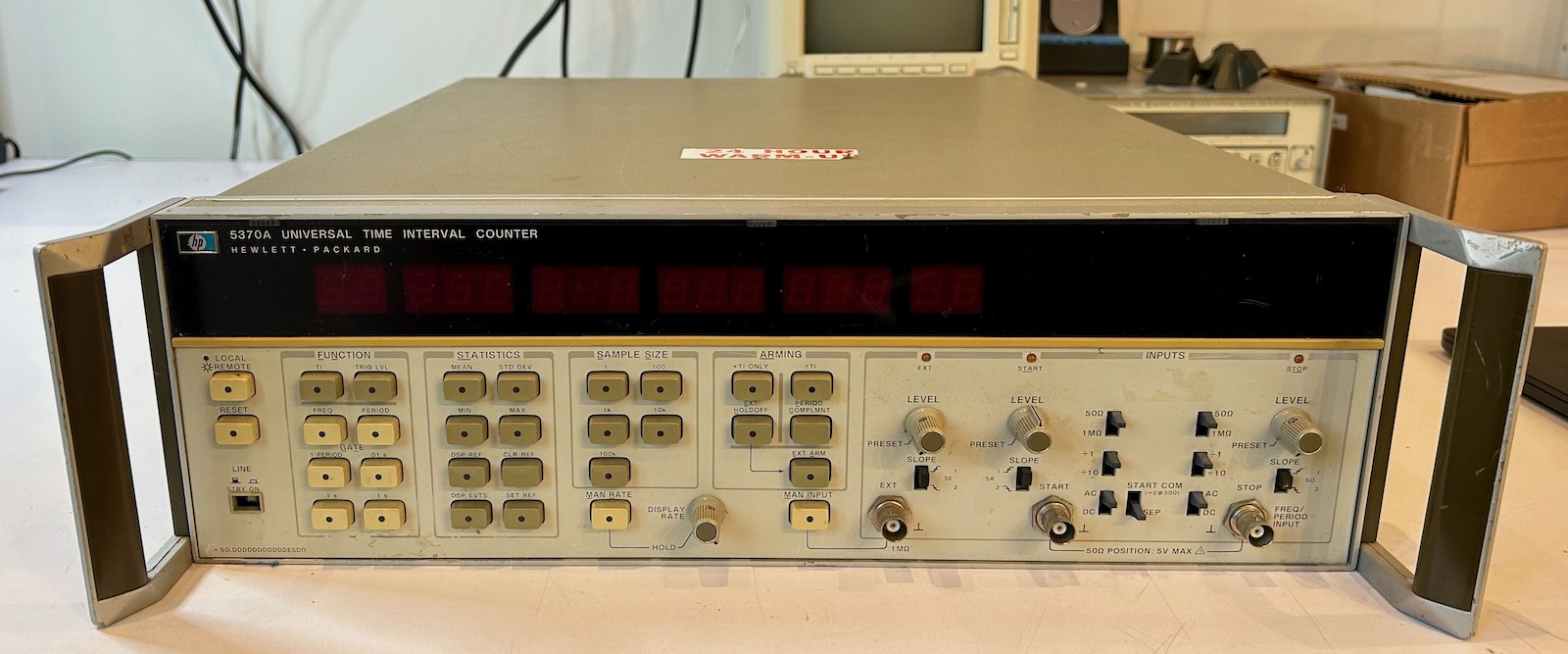
The 5370A is a pretty popular device among time nuts: it has a precision of 20ps for single-shot time interval measurements, amazing for a device that was released in 1978, and even compared to contemporary time interval counters it’s still a decent performance. The 74LS chips in mine have a 1981 time code which makes the unit a whopping 44 years old.
But after I plugged it in and pressed the power button, smoke and a horrible smell came out after a few minutes.
I had just purchased myself hours of entertainment!
Inside the HP 5370A
It’s trivial to open the 5370A:
- remove the 4 feet in the back by removing the Philips screws inside them.
- remove a screw to release the top or bottom cover
 (Click to enlarge)
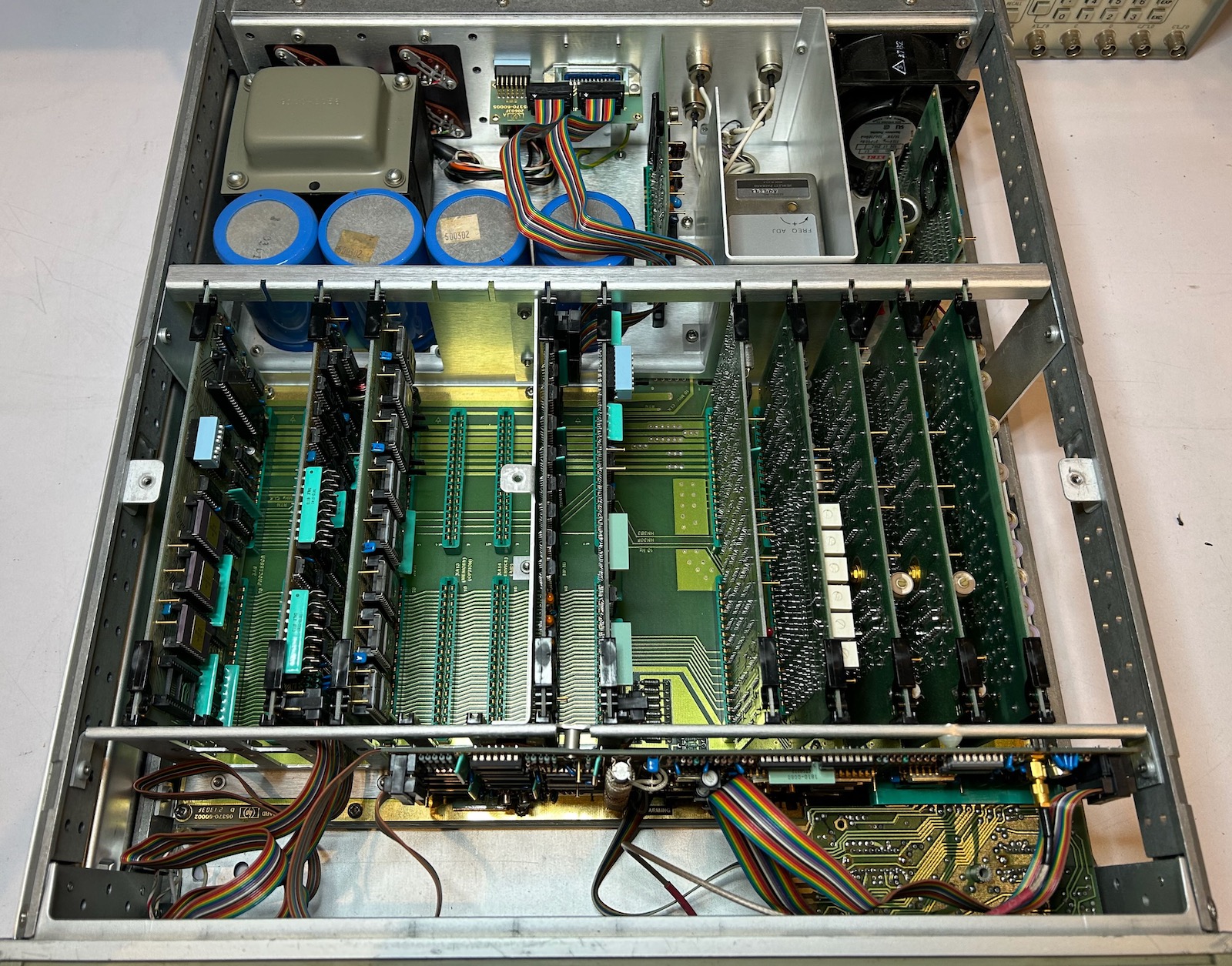
Once inside, you can see an extremely modular build: the center consists of a motherboard with 10 plug-in PCBs, 4 on the left for an embedded computer that’s based on an MC6800 CPU, 6 on the right for the time acquisition. The top has plug-in PCBs as well, with the power supply on the left and reference clock circuitry on the right. My unit uses the well known HP 10811-60111 high-stability OCXO as 10MHz clock reference. The bottom doesn’t have plug-in PCBs. It has PCBs for trigger logic and the front panel.
This kind of modular build probably adds significant cost, but it’s a dream for servicing and tracking down faults. To make things even easier, the vertical PCBs have a plastic ring or levers to pull them out of their slot! There are also plenty of generously sized test pins and some status LEDs.
High Stability Reference Clock with an HP 10811-60111 OCXO
Since the unit has the high stability option, I have now yet another piece of test equipment with an HP 10811-60111. OCXOs are supposed to be powered on at all time: environmental changes tend to stress them out and result in a deviation of their clock speed, which is why there’s a “24 hour warm-up” sticker on top of the case. It can indeed take a while for an OCXO to relax and settle back into its normal behavior, though 24 hours seems a bit excessive.
The 5370A has a separate always-on power supply just for the oven of the OCXO to keeps the crystal at constant temperature even when the power switch on the front is not in the ON position. Luckily, the fan is powered off when the front switch is set to stand-by.1
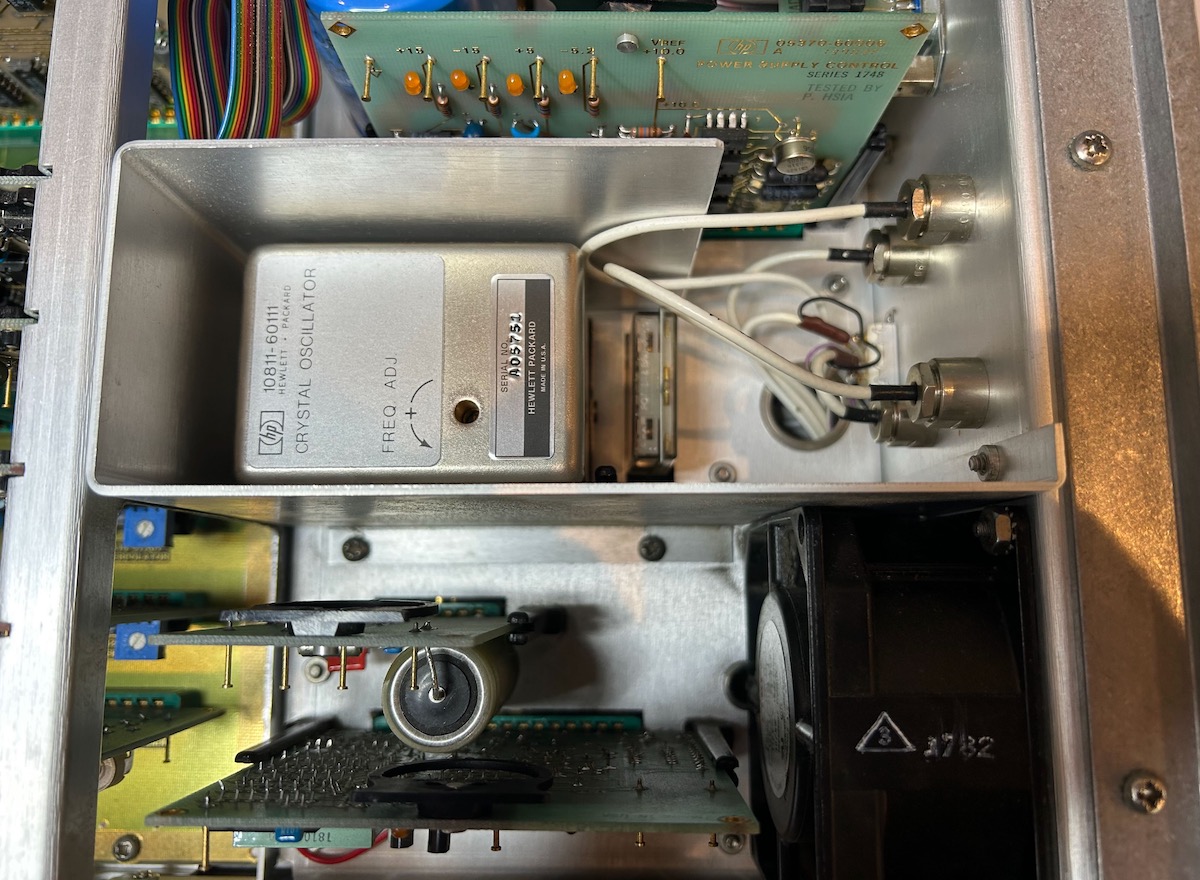
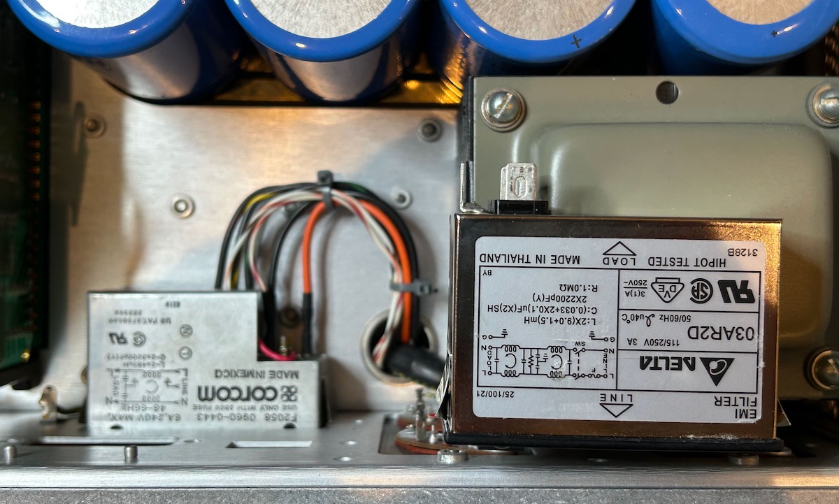
In the image above, from top to bottom, you can see:
- the main power supply control PCB
- the HP 10811-60111 OCXO. To the right of it is the main power relay.
- the OCXO oven power supply
- the reference frequency buffer PCB
These are the items that will play the biggest role during the repair.
RIFA Capacitors in the Corcom F2058 Power Entry Module?
Spoiler: probably not…
After plugging in the 5370A the first time, magic smoke came out of it along with a pretty disgusting chemical smell, one that I already knew from some work that I did on my HP 8656A RF signal generator.
I unplugged the power, opened up the case, and looked for burnt components but couldn’t find any. After a while, I decided to power the unit back on and… nothing. No smoke, no additional foul smell, but also no display.
One of common failure mode of test equipment from way back when are RIFA capacitors that sit right next to the mains power input, before any kind of power switch. Their primary function is to filter out high frequency noise that’s coming from the device and reduce EMI. RIFAs have a well known tendency to crack over time and eventually catch fire. A couple of years ago, I replaced the RIFA capacitors of my HP 3457A, but a general advice is to inspect all old equipment for these gold colored capacitors. However, no such discrete capacitors could be found.
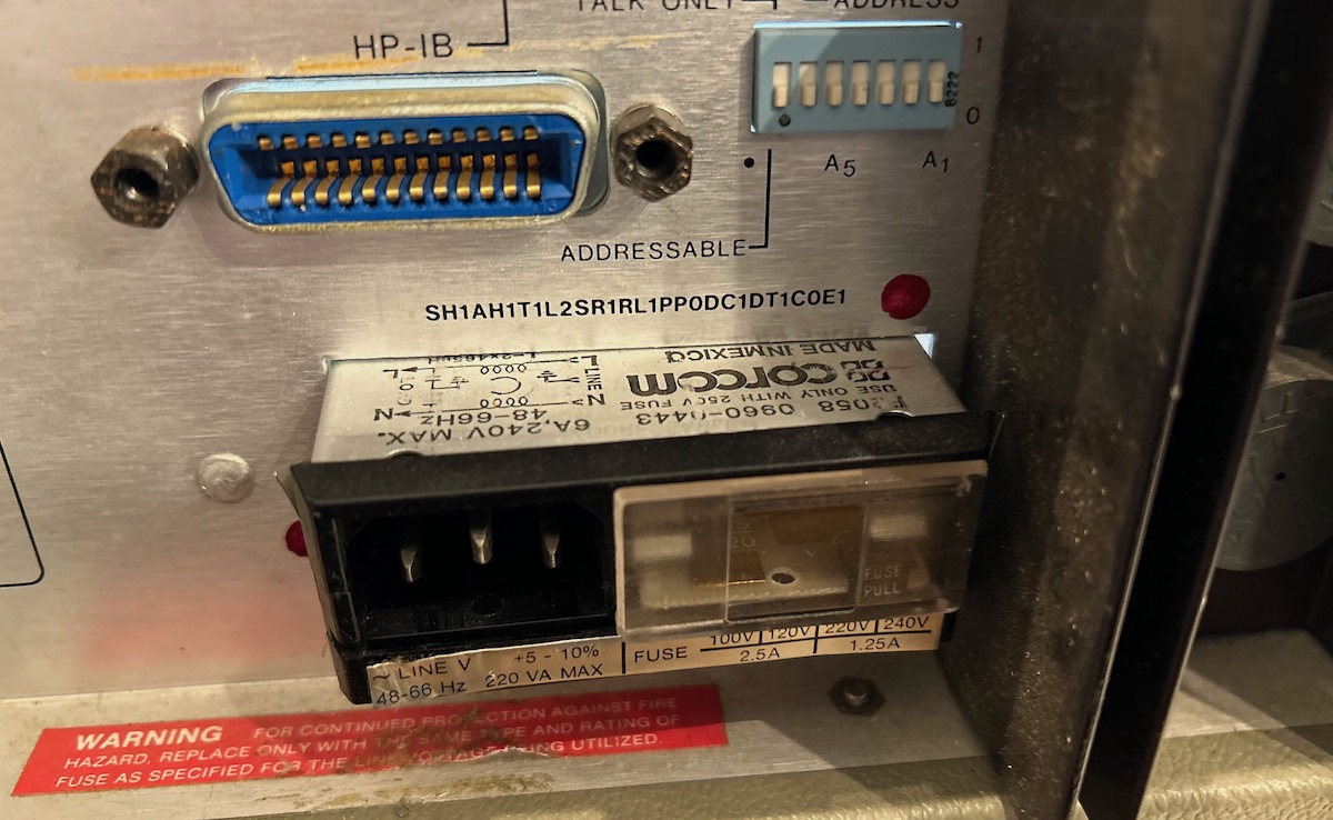
But that doesn’t mean they are not there: like a lot of older HP test equipment, the 5370A uses a Corcom F2058 line power module that has capacitors embedded inside.
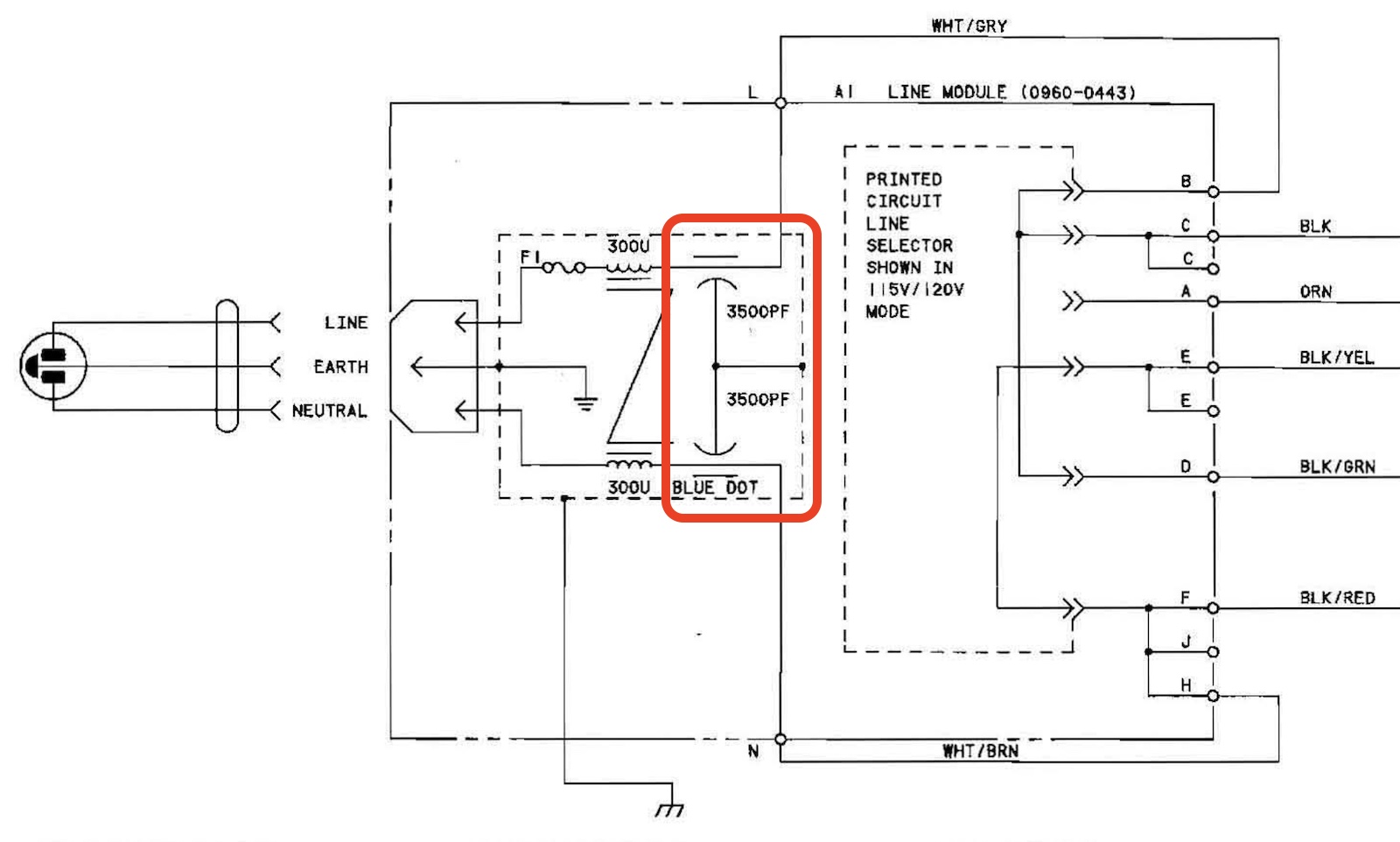
Below is the schematic of the Corcom F2058 (HP part number 0960-0443). The capacitors are marked in red. You can also see a fuse F1, a transformer and, on the right, a selector that can be used to configure the device for 100V, 115V/120V, 220V and 230V/240V operation.
 (Click to enlarge)
There was a bad smell lingering around the Corcom module, so I removed it to check it out. There are metal clips on the left and right side that you need to push in to get the module out. It takes a bit of wiggling, but it works out eventually. Once removed, however, the Corcom didn’t really have a strong smell at all. I couldn’t find any strong evidence online that these modules have RIFAs inside them, so for now, my conclusion is that they don’t have them and that there’s no need to replace them.
Module replacement
In the unlikely case that you want to replace the Corcom module, you can use this $20 AC Power Entry Module from Mouser. One reason why you might want to do this is because the new module has a built-in power switch. If you use an external 10 MHz clock reference instead of the 10811 OCXO, then there’s really no need to keep the 5370A connected to the mains all the time.
There are two caveats, however:
-
while it has the same dimensions as the Corcom F2058, the power terminals are located at the very back, not in an indented space. This is not a problem for the 5370A, which still has enough room for both, but it doesn’t work for most other HP devices that don’t have an oversized case. You can see that in the picture below:
-
Unlike the Corcom F2058, the replacement only feeds through the line, neutral and ground that’s fed into it. You’d have to choose one configuration, 120V in my case, and wire a bunch of wires together to drive the transformer correctly. If you do this wrong, the input voltage to the power regulator will either be too low, and it wont work, or too high, and you might blow up the power regulation transistors. It’s not super complicated, but you need to know what you’re doing.
15V Rail Issues
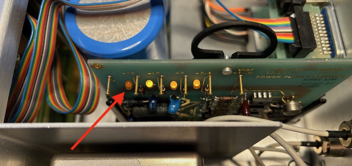
After powering the unit back up, it still didn’t work, but thanks to the 4 power rail status LEDs, it was immediately obvious that +15V power rail had issues.
A close-by PCB is the reference frequency buffer PCB. It has a “10 MHz present” status LED that didn’t light up either, suggesting an issue with the 10811 OCXO, but I soon figured out that this status LED relies on the presence of the 15V rail.
Power Suppy Architecture
The 5370A was first released in 1978, decades before HP decided to stop including detailed schematics in their service manuals. Until Keysight, the Company Formerly Known as HP, decides to change its name again, you can download the operating and service manual here. If you need a higher quality scan, you can also purchase the manual for $10 from ArtekManuals2. The diagrams below were copied from the Keysight version.
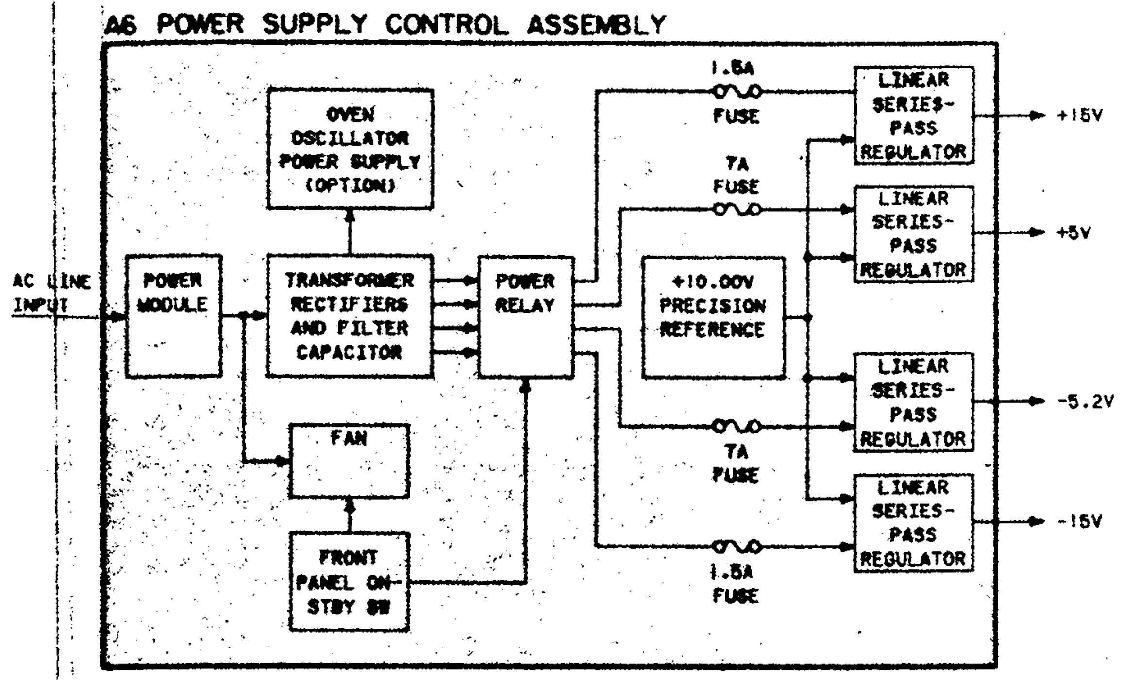
The power supply architecture is straightforward: the line transformer has 5 separate windings, 4 for the main power supply and 1 for the always-on OCXO power supply. A relay is used to disconnect the 4 unregulated DC rails from the power regulators when the front power button is in stand-by position, but the diode rectification bridge and the gigantic smoothing capacitors are located before the relay.3
For each of the 4 main power rails, a discrete linear voltage regulator is built around a power transistor, an LM307AN opamp and a smaller transistor for over-current protection, and a fuse. The 4 regulators share a 10V voltage reference.
The opamps and the voltage reference are powered by a simple +16.2V power rail built out of a resistor and a Zener diode.
 (Click to enlarge)
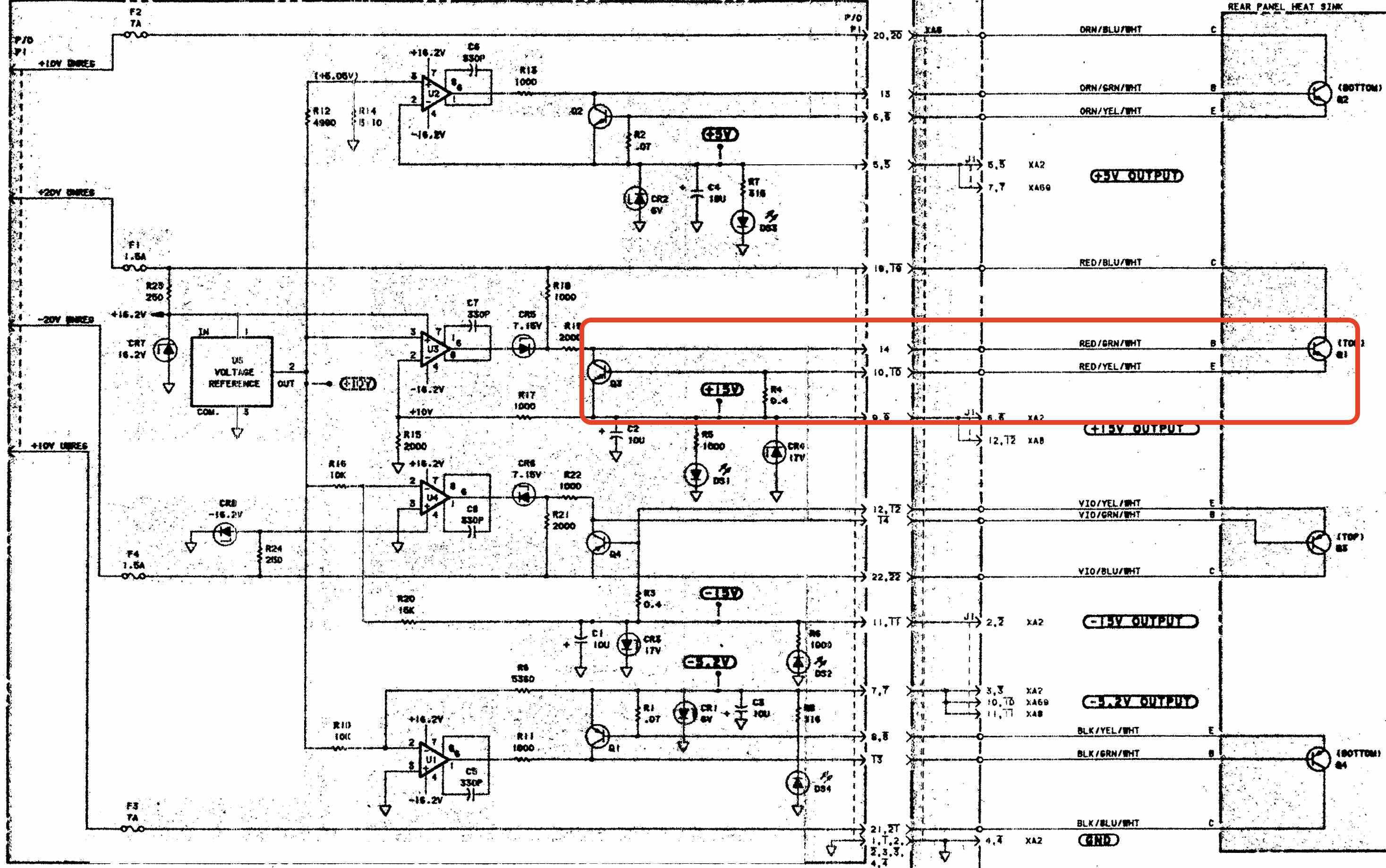
The power regulators for the +5V and -5.2V rails have a current sense resistor of 0.07 Ohm. The sense resistors for the +15V and -15V rails have a value of 0.4 Ohm. When the voltage across these resistors exceeds the 0.7V base-emitter potential of the bipolar transistors across them, the transistors start to conduct and pull down the base-emitter voltage of the power transistor, thus shutting them off. In the red rectangle of the schematic above, the +15V power transistor is on the right, the current control transistor on the left, and current sense resistor R4 is right next to the +15V label.
Using the values of 0.4 Ohm, 0.07 Ohm and 0.7V, we can estimate that the power regulators enter current control (and reduce the output voltage) when the current exceeds 10A for the +5/-5.2V rails and 1.5A for the +15/-15V rails. This more or less matches the value of the fuses, which are rated at 7A and 1.5A respectively.
Power loss in these high current linear regulators is signficant and the heat sink in the back become pretty hot. Some people have installed an external fan to cool it down a bit.
Fault Isolation - It’s the Reference Frequency Buffer PCB!
I measured a voltage of 8V instead of 15V. I would have prefered if I had measured no voltage at all, because a lower than expected voltage suggests that the power regulator is in current control instead of voltage control mode. In other words: there’s a short somewhere which results in a current that exceeds what’s expected under normal working conditions. Such a short can be located anywhere.
But this is where the modular design of the 5370A shines: you can unplug all the PCBs, check the 15V rail, and if it’s fine, add back PCBs until it’s dead again. And, indeed, with all the PCBs removed, the 15V rail worked fine. I first added the CPU related PCBs, then the time acquisition PCBs, and the 15V stayed healthy. But after plugging in the reference frequency buffer PCB, the 15V LED went off and I measured 8V again. Of all the PCBs, this one is the easiest one to understand.
The Reference Frequency Buffer Board
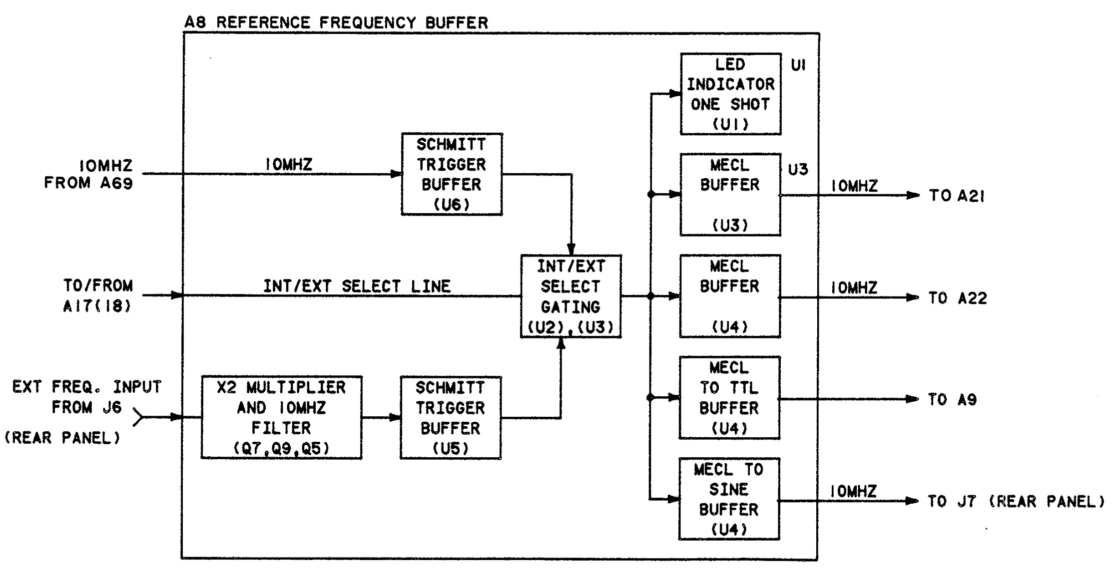
The reference frequency buffer board has the following functionality:
-
Convert the internally generated 10MHz frequency to emitter-coupled logic (ECL) signaling.
The 5370A came either with the OCXO or with a lower performance crystal oscillator. These cheaper units were usually deployed in labs that already had an external reference clock network.
-
Receive an external reference clock of 5 MHz or 10 MHz, multiply by 2 in the case of 5 MHz, and apply a 10 MHz filter. Convert to ECL as well.
-
Select between internal and external clock to create the final reference clock.
-
Send final reference clock out as ECL (time measurement logic), TTL (CPU) and sine wave (reference-out connector on the back panel).
During PCB swapping, the front-panel display had remained off when all CPU boards were plugged in. Unlike later HP test equipment like the HP 5334A universal counter, the CPU clock of the 5370A is derived from the 10 MHz clock that comes out of this reference frequency buffer PCB4, so if this board is broken, nothing works.
When we zoom down from block diagram to the schematic, we get this:
 (Click to enlarge)
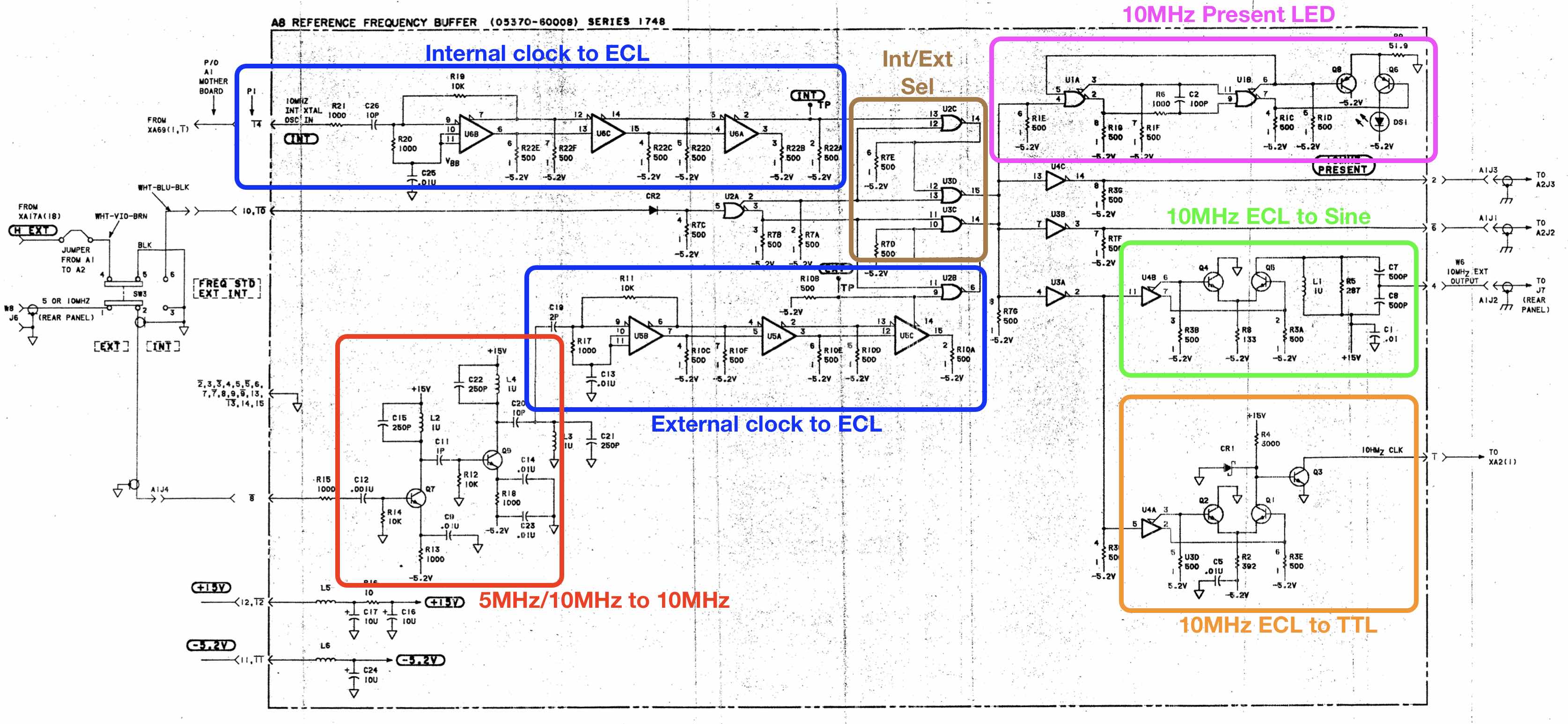
Leaving aside the debug process for a moment, I thought the 5 MHz/10 MHz to 10 MHz circuit was intriguing. I assumed that it worked by creating some second harmonic and filter out the base frequency, and that’s kind of how it works.
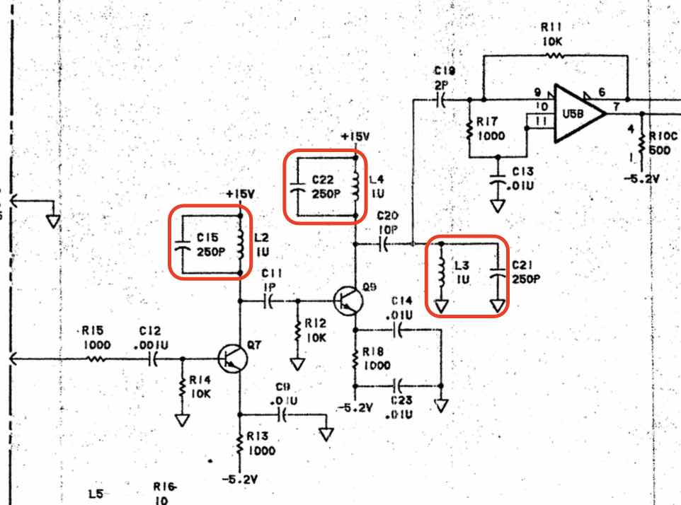
There are 3 LC tanks with an inductance of 1 uH and a capacitance of 250pF, good for a natural resonance frequency of \(f = \frac{1}{2 \pi \sqrt{ L C }}\) = 10.066 MHz. The first 2 LC tanks are each part of a class C amplifier. The 3rd LC tank is an additional filter.
The incoming 5 MHz or 10 MHz signal periodically inserts a bit of energy into the LC tank and nudges it to be in sync with it. This circuit deserves a blog post on its own.
Fixing the Internal Reference Clock
When you take a closer look at the schematic, there are 2 points that you can take advantage of:
- The only part on the path from the internal clock input to the various internal outputs that depends on the 15V rail is the ECL to TTL conversion circuit. And that part of the 15V rail is only connected to 3k Ohm resistor R4.
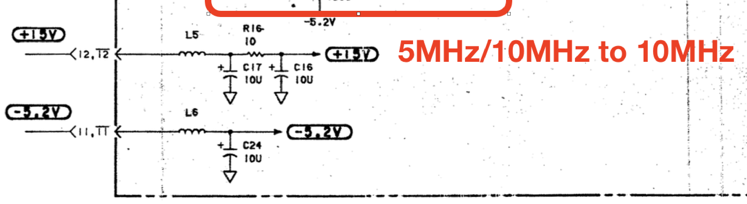
- Immediately after the connector, 15V first goes through an L/C/R/C circuit.
In the process of debugging, I noticed the following:
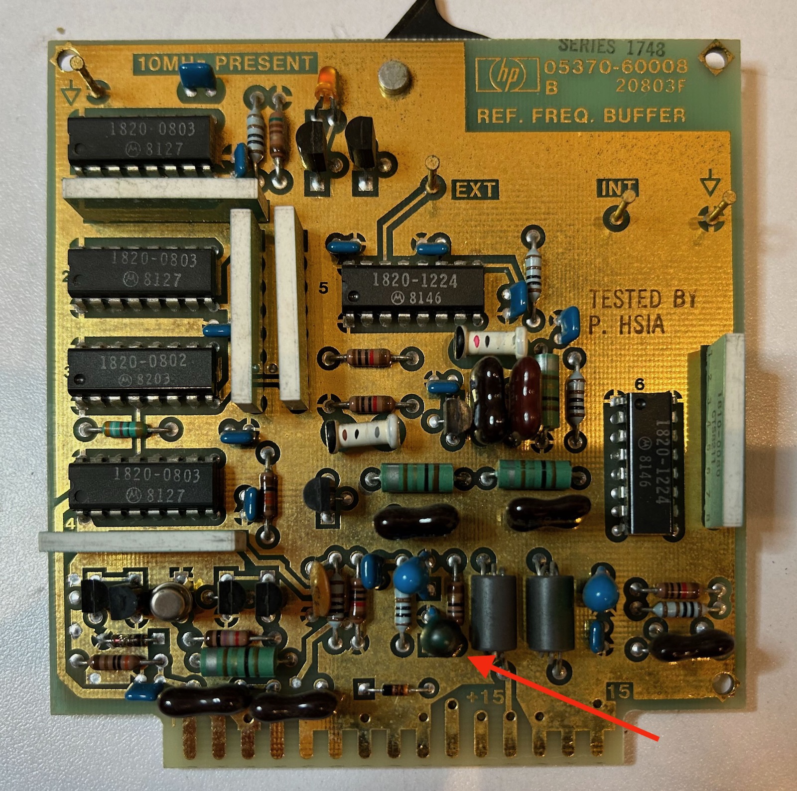
The arrow points to capacitor C17, which looks suspiciously black. I found the magic smoke generator.
This was the plan of attack:
- Replace C17 with a new 10uF capacitor.
- Remove resistor R16 to decouple the internal 15V rail from the external one.
- Disconnect the top side of R4 from the internal 15V and wire it up straight to the connector 15V rail so that only the ECL to TTL conversion circuit has 15V power.
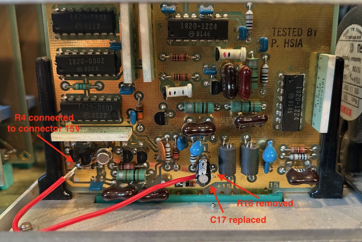
It’s an ugly bodge, but after these 3 fixes, I had a nice 10MHz ECL clock signal on the output clock test pin.
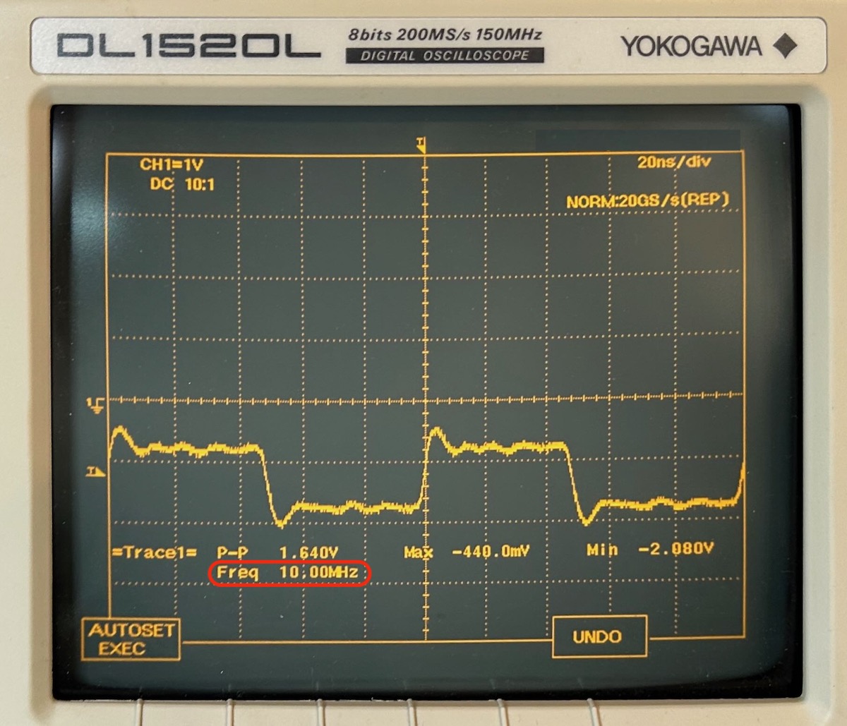
The 5370A was alive and working fine!
Fixing the External Reference Clock
I usually connect my test equipment to my GT300 frequency standard, so I really wanted to fix that part of the board as well.
This took way longer than it could have been…
I started by replacing the burnt capacitor with a 10uF electrolytic capacitor and reinstalling R16. That didn’t go well: this time, the resistor went up in smoke. My theory is that, with shorted capacitor C17 removed, there was still another short and now the current path had to go through this resistor. Before burning up, this 10 Ohm resistor measured only 4 Ohms.
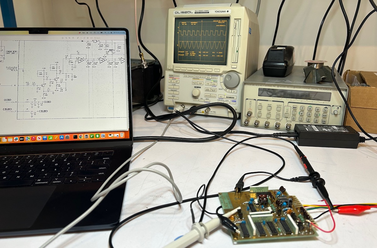
I then removed the board and created a stand-alone setup to debug the board in isolation. With that burnt up R16 removed again, 15V applied to the internal 15V and a 10 MHz signal at the external input, the full circuit was working fine.
I removed capacitor C16, checked it with an LCR tester and the values nicely in spec.
Unable to find any real issues, I finally put in a new 10 Ohm resistor, put a new 10uF capacitor for C16 as well, plugged in the board and… now the external clock input was working fine too?!
So the board is fixed now and I can use both the internal and external clock, but I still don’t understand why R16 burnt up after the first capacitor was replaced.
Future work
The HP 5370A is working very well now. Once I have another Digikey order going out, I want to add 2 tantalum capacitors to list and install those instead of the electrolytics that I used to repair.
I can’t find it back, but 2 easy modifications were suggested on the time-nuts email list:
-
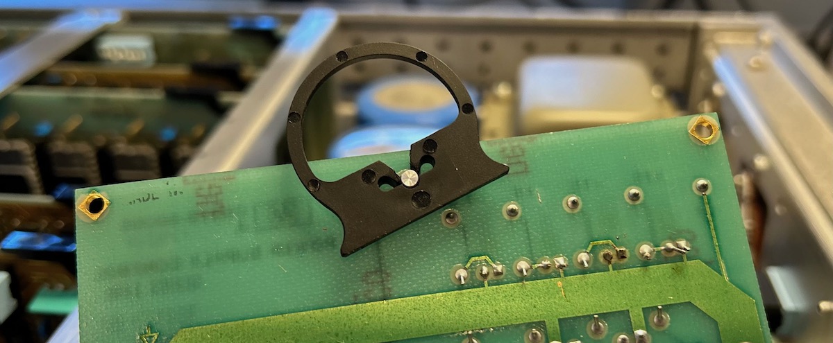
Drill a hole through the case right above the HP 10811-60111 to have access to the frequency adjust screw.
An OCXO is supposed to be immune to external temperature variations, but when you’re measuring picoseconds, a difference in ambient temperature can still have a minor impact. With this hole, you can keep the case closed while calibrating the internal oscillator.
-
Disconnect the “10 MHz present” status LED on the reference clock buffer PCB. Apparently, this circuit creates some frequency spurs that can introduce some additional jitter on the reference clock.
If you’re really hard core:
-
Replace the entire CPU system by a modern CPU board
More than 10 years ago, the HP5370 Processor Replacement Project reverse engineered the entire embedded software stack, created a PCB based on a Beagle board with new firmware. PCBs are not available anymore, but one could easily have a new one made for much cheaper than what it would have cost back then.
References
-
Keysight - 5370A Universal Time Interval Counter Operating and Service Manual
-
Introduction of the HP 5370A with extensive explanations of how it works under the hood.
-
HP Application Note 200-3 - Fundamentals of Time Interval Measurements
Footnotes
-
My HP 8656A RF signal generator has an OCXO as well. But the fan keeps running even when it’s in stand-by mode, and the default fan is very loud too! ↩
-
Don’t expect to be able to cut-and-paste text from the ArtekManuals scans, because they have some obnoxious rights managment that prevents this. ↩
-
Each smoothing capacitor has a bleeding resistor in parallel to discharge the capacitors when the power cable is unplugged. But these resistors will leak power even when the unit is switched off. Energy Star regulations clearly weren’t a thing back in 1978. ↩
-
The CPU runs at 1.25 MHz, the 10 MHz divided by 8. ↩