HP 33120A Repair - Shutting Down the Eye of Sauron
- Introduction
- Opening Up an HP 33120A
- A Walk Through the Block Diagram
- Bug Hunting
- Zener Replacement
- Staring at the Eye of Sauron
- FLIR IR Imaging
- To Destroy a PCB in Order to Save It
- Circuit Reconstruction
- Success!
- Trust but Verify
- Conclusion
- References
Introduction
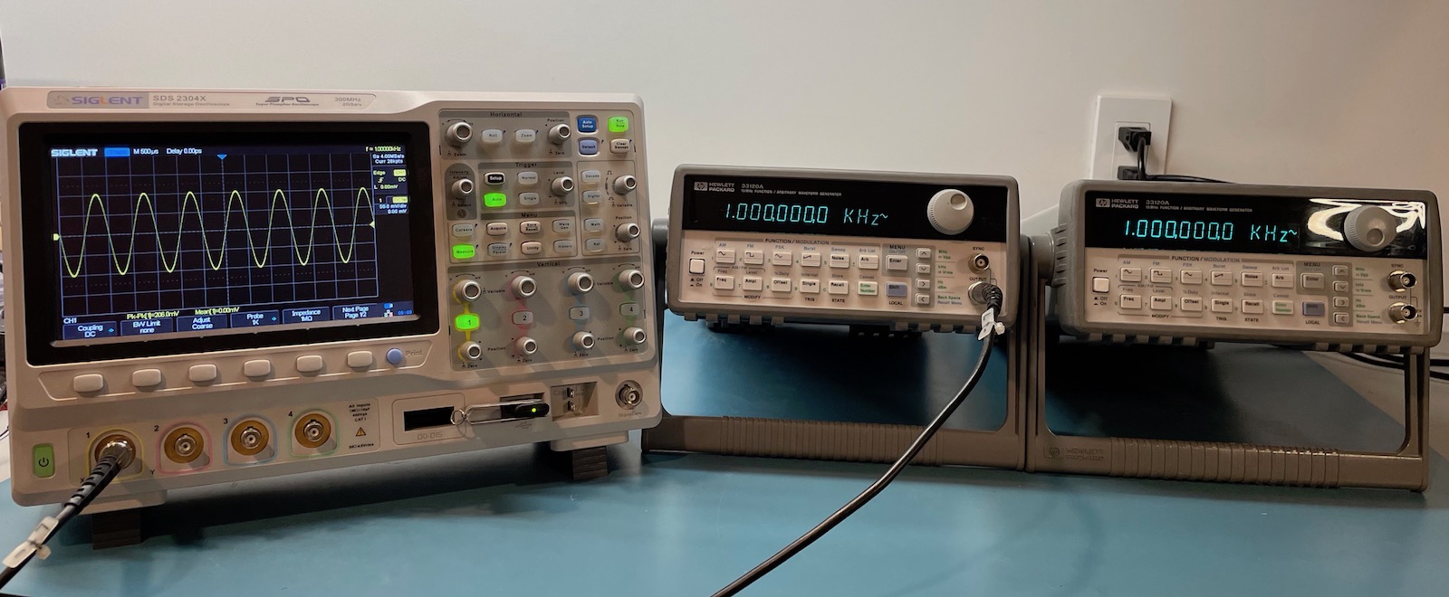
When the soon-to-be-defunct startup of a friend closed down one of its labs, he was allowed to take a few toys home. Part of the loot were 2 HP 33120A 15MHz function/arbitrary waveform generators.

They used to be pretty popular, and you can often find them secondhand on eBay or Craiglist for around $250. That doesn’t mean that they’re exceptional instruments. The datasheet praises a straightforward and intuitive front-panel user interface that gets often ridiculed by actual users. They only have a 12-bit DAC and a sampling rate of 40MSa/s, the specs for phase noise, harmonics, rise time are underwhelming, and one channel per unit can be a limitation too. But at least there’s a GPIB and an RS-232 interface to create automated test and measurement setups.
A quick look at the Siglent website shows that a 2 channel 30MHz SDG1032X exceeds the 33120A for every feature, for $359. So there’s really no good reason to buy a secondhand 33120A, unless you have a legacy automated setup that requires one.
But enough about relative deficiencies, it’s still a nice piece of kit for a home lab, especially when acquired for free.
One day while he was cleaning up his garage, I passed by and saw the two units sitting there on a shelve gathering dust. I’ve never had a use for a signal generator (does anyone ever?), but I love to play with test equipment just for the fun of it, so I borrowed them and took them home. That was 2 years ago.
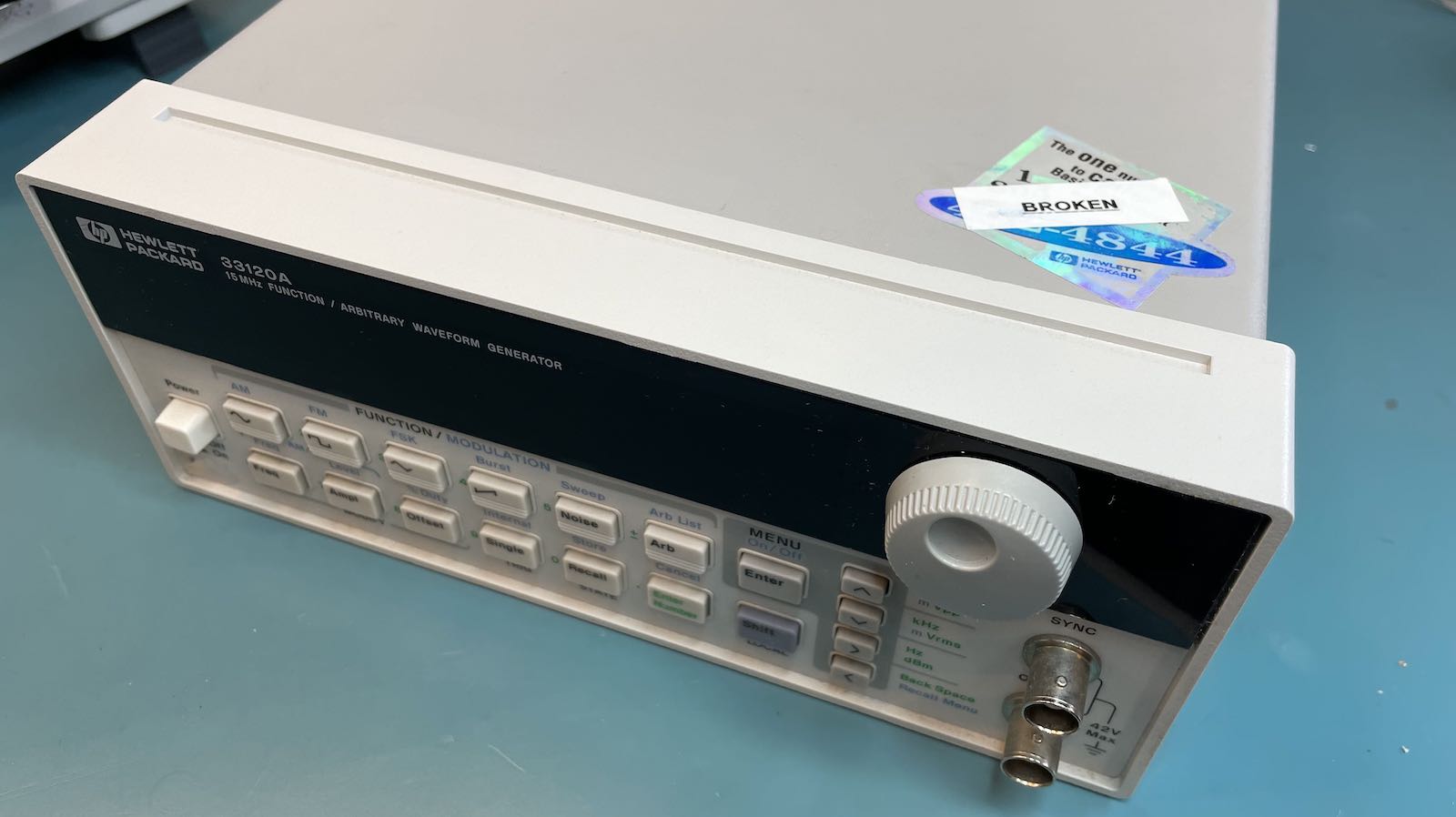
After powering them up, it was obvious that only one of them was working correctly, sending out the default 1kHz 100mVpp sine wave. The other one had a 1kHz square wave signal on the SYNC output, but the main output was dead.
It was time to open them up and have a look inside!
Opening Up an HP 33120A
I almost feel embarassed about posting how to open instructions for a 33120A: it’s just too simple. But I’ve overdone it for other devices, so let’s just get it over with…
There’s a grand total of 3 Torx T15 screws:
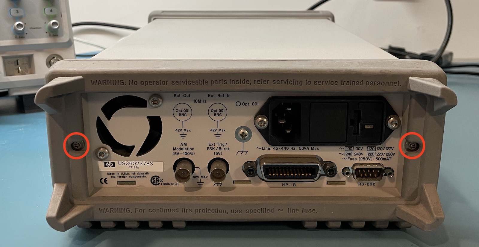
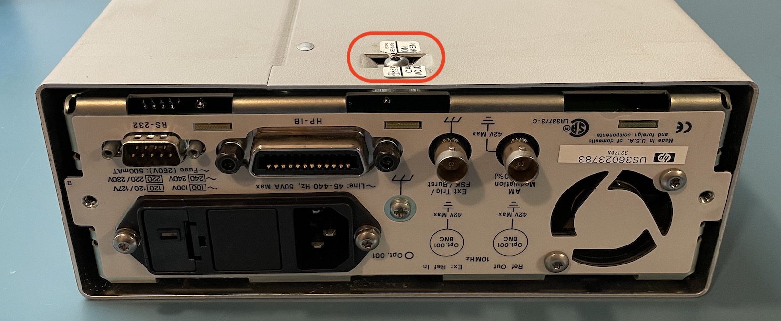
After that, you can slide off the enclosure, as long as you’ve already removed the handle.
 (Click to enlarge)
There’s a large number of integrated circuits on the left, but towards the front, there’s plenty of small individual analog components such as transistors, resistors and capacitors as well. That’s good, because those are much easier to replace.
When you click on that top view picture, you’ll get a high resolution version. Go ahead and check out if you can see anything interesting. We’ll come back to that later.
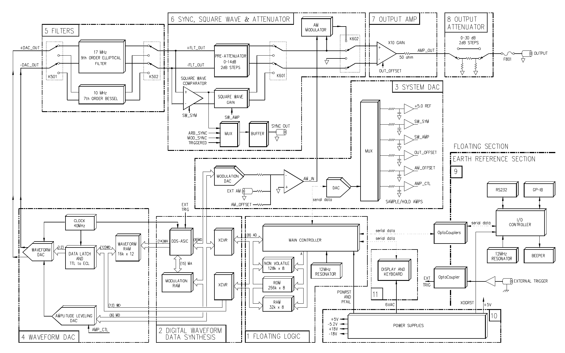
A Walk Through the Block Diagram
The service manual is excellent, with an extensive section dedicated to theory of operation and full schematics. My only minor complaints are that the component annotation in the schematics isn’t PDF searchable, and that the component list has ranges like this: C714-C719, which means that a search for, say, C716 won’t turn up anything.
The block diagram is split up 11 sections. Each section is a major functional block, and a separate schematic page as well. What I absolutely love is that the leading number of components is the section number as well. In other words, if you’re looking at the PCB and see resistor R723, you know right away that it’s part of section 7, the output amplifier. It’s a huge time saver when trying to match a component against a schematic.
 (Click to enlarge.)
You can safely skip to the next section if you’re not interested in the architecture of a 33120A.
The different sections have the following functionatily:
-
Floating Logic
This section contains a small microcomputer built around an 80C196 microcontroller, 256KB of ROM, 32KB of RAM, and 128KB of flash memory. It’s responsible for managing the signal generating functions.
Like the rest of the signal generating functions, it has a floating ground which allows a user to connect the ground of the output to any reference point they want.
The controller has a serial link to the IO controller that’s responsible for all control interactions with the outside world. (See below.) The serial link goes through opto-couplers because the IO controller uses an earth referenced ground.
-
Digital Waveform Data Synthesis
The 33120A uses a pretty standard and straightforward way to generated signals: it has a RAM with waveform data and fetches waveform values from this RAM, skipping from one address to the next based on the selected output frequency.
It also has support for AM, FM and FSK modulation.
This section contains an ASIC that generates that addresses that must be fetched from the main waveform RAM. It also generates that signal that will be used for AM: you’d think that amplitude modulation is done in the digital domain, but it actually uses an analog multiplier.
-
System DAC
We’re deviating from the main pipeline for a moment. The System DAC generates all kinds of mostly static control voltages that will be used in the analog pipeline. Things like the DC offset voltage of the output signal, etc.
-
Waveform DAC
This block fetches data values from a waveform RAM and applies it to a DAC. The DAC always runs at 40MHz, irrespective of the desired output frequency of the signal that must be generated.
The amplitude of the signal that comes out of the DAC can be controlled with a range of only ±2dB. Further amplitude control is performed later in the pipeline.
-
Filters
Now fully in the analog domain, some serious amount of filtering is needed to get rid of aliasing effects. Sine and square waves are going through a steep 9th order filter, the rest goes through a 7th order filter.
-
Sync, Square Wave and Attenuator
An attenuator in this block reduces the amplitude in steps of 2dB but only down to -14dB, which is why it’s called the pre-attenuator.
There’s also a SYNC generator, and a square wave generator which are created by using a comparator opamp against the signal that comes out of the filter block.
-
Output Amplifier
The output amplifier amplifies the signal by a fixed factor of 10 and also adds the fixed DC offset if requested. It’s designed to drive a 50Ohm load.
-
Output Attenuator
The main attenuator can reduce the signal from 0dB to -30dB with, again, steps of 2dB.
There are 4 stages with roughly double the attenuation that can be switched in and out of the main signal path.
-
Earth Referenced Logic
This section contains the IO controller that takes care of the front panel user interface, the RS232 serial port, the GPIB interface and a beeper.
-
Power Supply
There are 5 main voltages: +5V, -5.2V, +18V, -18V, and +5V.
There are 2 +5V rails, one for the floating ground electronics and the other for the earth referenced ground.
-
Display and Keyboard
Like all the HP instruments of its day, the 33120A uses a vacuum fluorescent display (VFD). These have a tendency to fade over time and replacment parts are often pricey.
On my units, they are in fantastic shape.
Bug Hunting
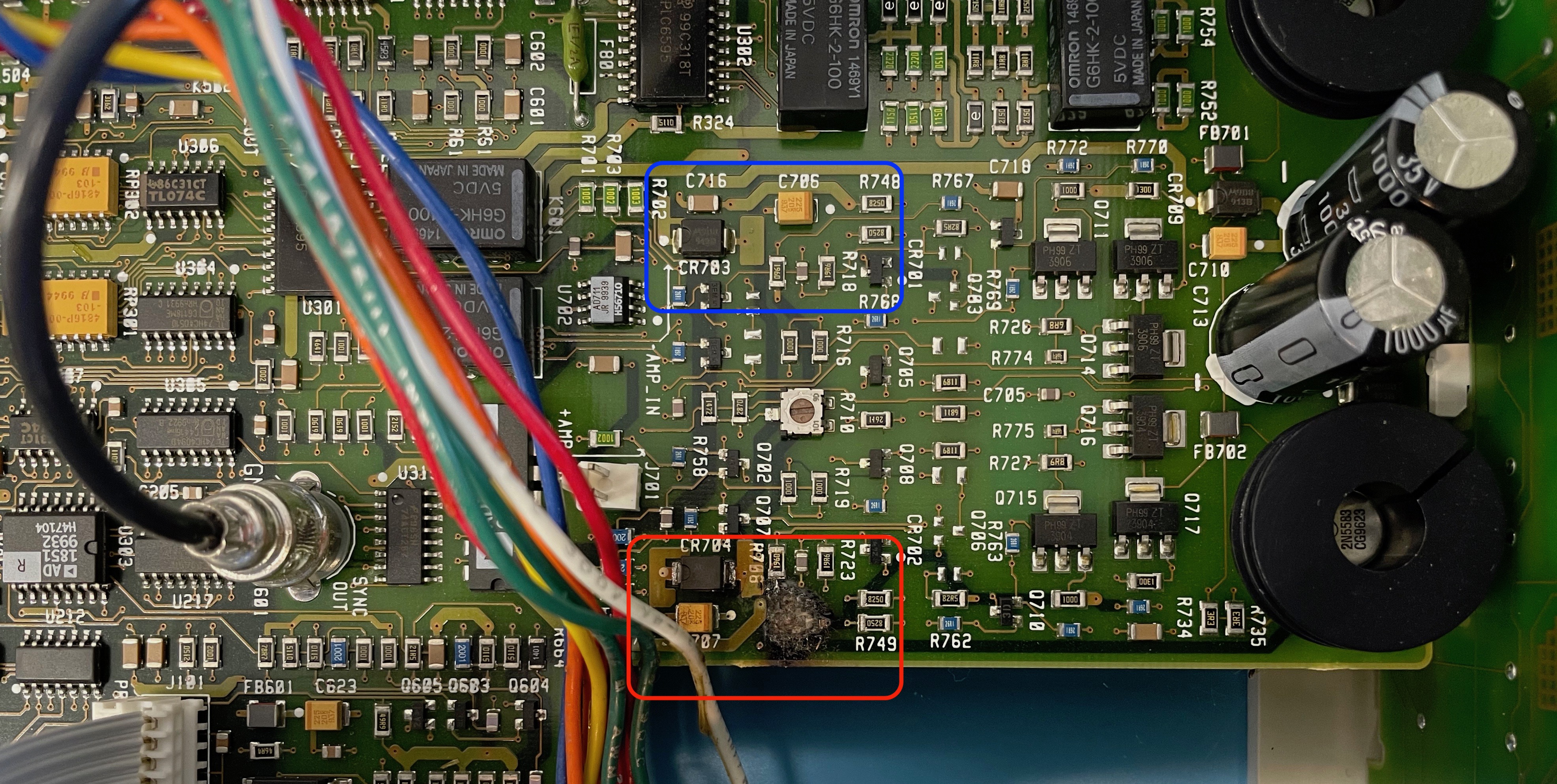
If you tried to look for something interesting in the previous picture, chances are that you noticed the area that’s marked in red:
 (Click to enlarge)
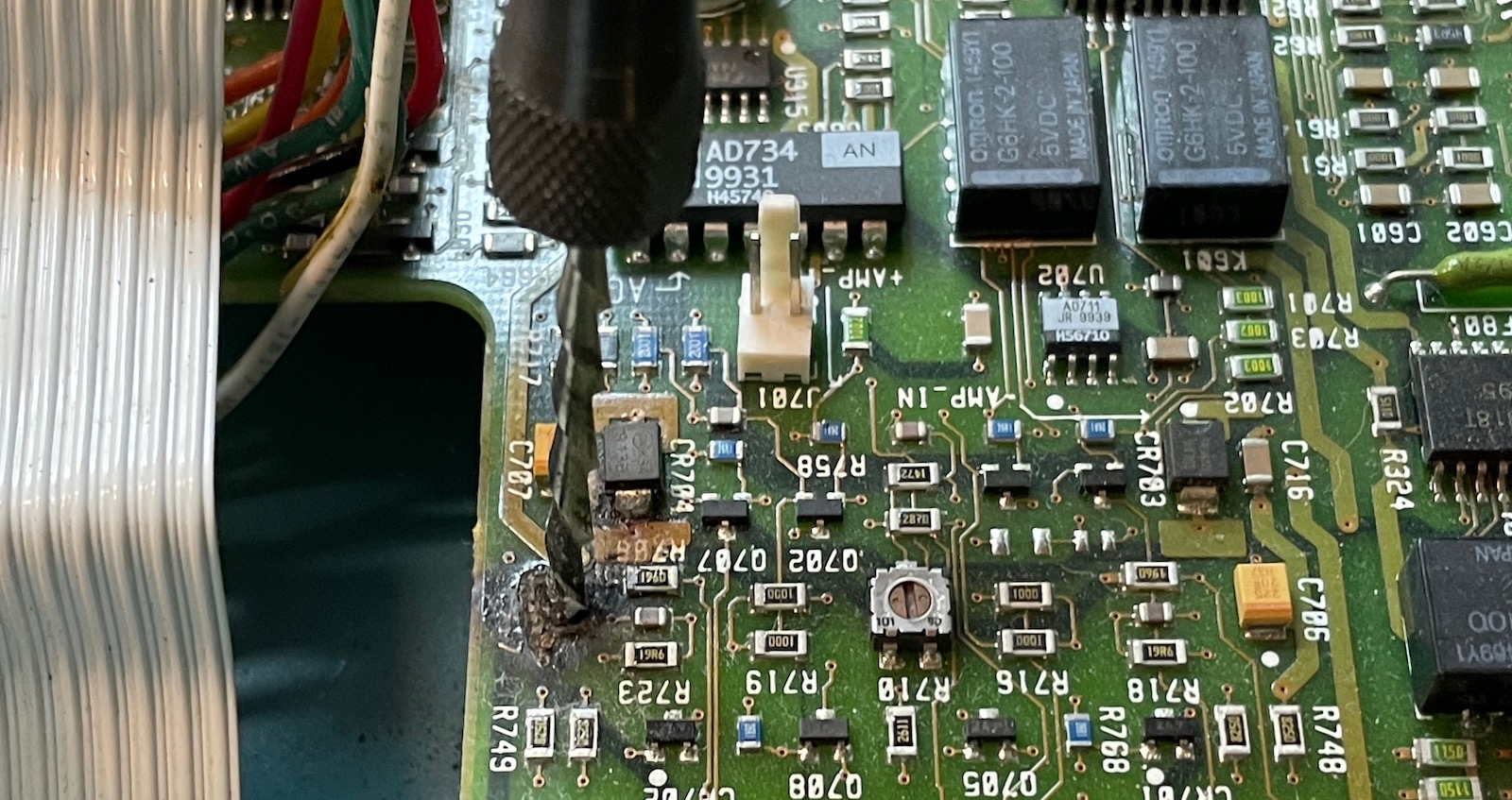
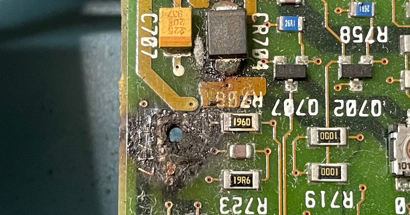
You can’t quite see it on the broken device but capacitor C717 has completely disappeared and there’s a very clear burn mark. That’s not good. In addition to the burnt area, we can also see that there is heavy PCB discoloration around components C707, CR703 (a 3.3V Zener diode), and R706.
This section of the PCB is part of the output amplifier. The DAC produces a positive and a negative version of the signal, and these 2 signals get passed through all the way to the output amplifier. There is a strong top/bottom symmetry in both the schematic and the PCB, and almost every component exists twice.
For example, the 9 components in the red area are present in the blue area as well. Even if we didn’t have the schematic, this would have been very useful to determine if certain components had been damaged, and what kind of value they were.
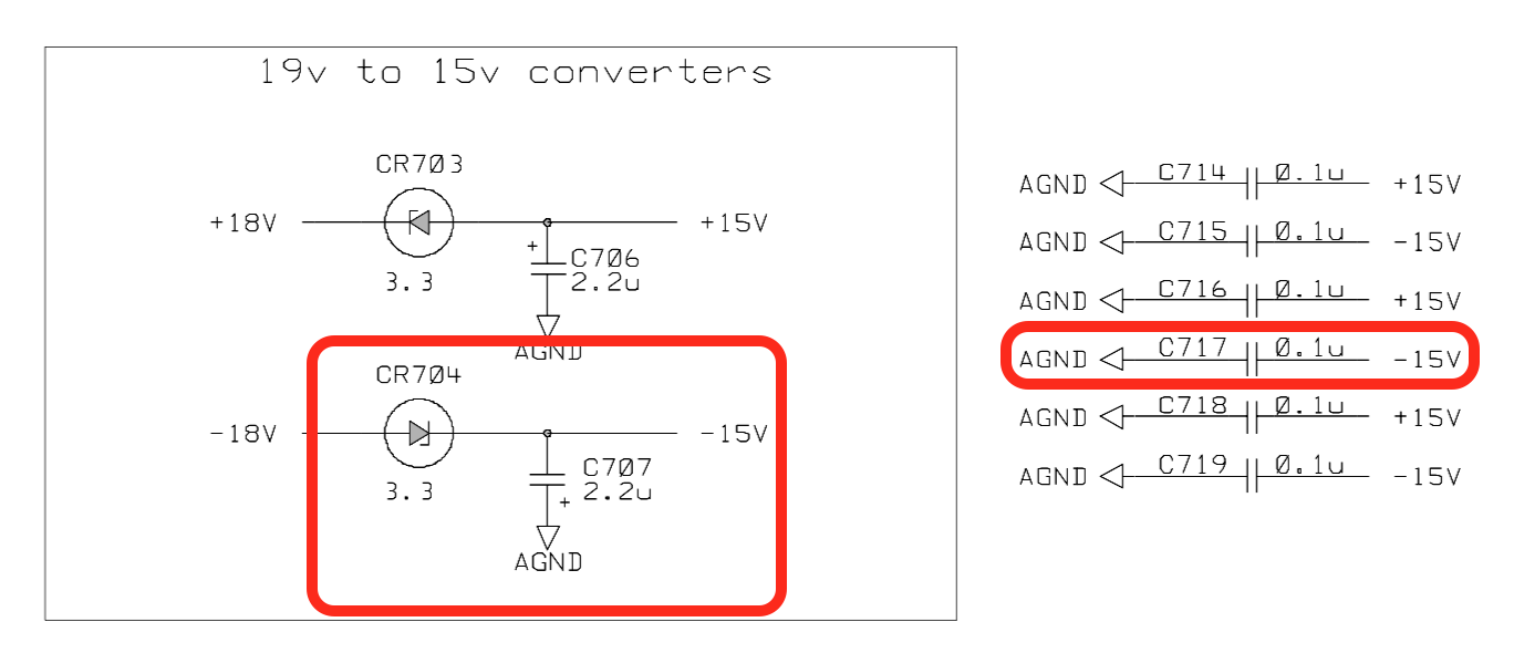
But we have the schematics, and they show that Zener CR704 creates -15V from the -18V rail, and that C707 and C717 are decoupling caps on this -15V rail.
Zener Replacement
If you’re trying to do electronics repair, you should always check power rails first. A quick check on the CR704 pins showed that the -18V rail was fine, but the -15V rail was not.
So we have a burn scar, a missing (vaporized?) decoupling cap, and a broken Zener. This now becomes a cause-and-effect problem. Did the Zener break because of the heat, or did heat develop because of a defective Zener? During extensive probing, I didn’t notice any magic smoke coming out of the burnt area, so I assumed that the Zener was the cause of it all.
Either way, it had to be replaced, so I ordered an Onsemi 1SMB5913BT3G at LCSC.
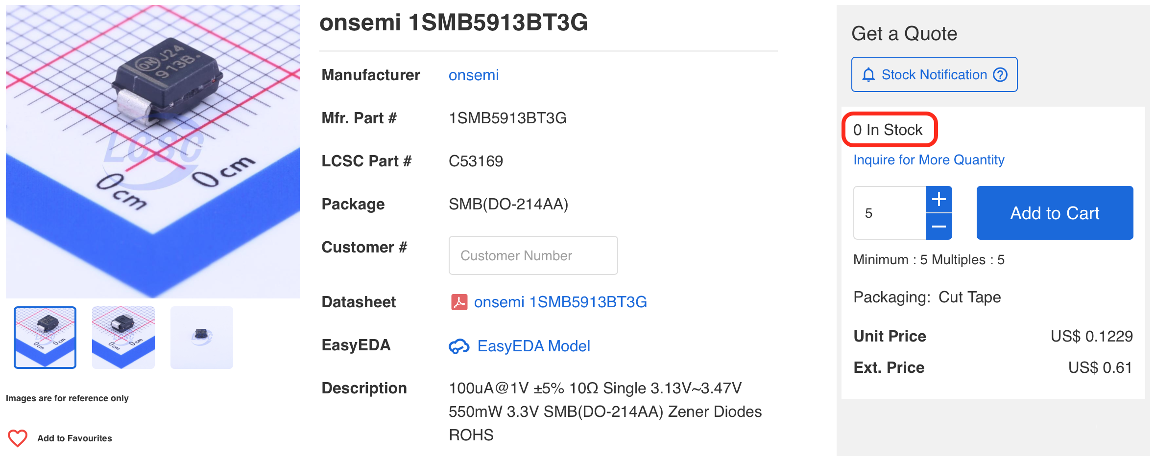
See that “0 In Stock”? At the time, LCSC was the only place where I was able to find such a Zener. DigiKey had, and still has, nothing available.
That was in April 2021. I lost interest in the repair and picked it back up 20 months later in December 2022 when I found the LCSC box… while cleaning up my garage.
Replacing the Zener was uneventful…
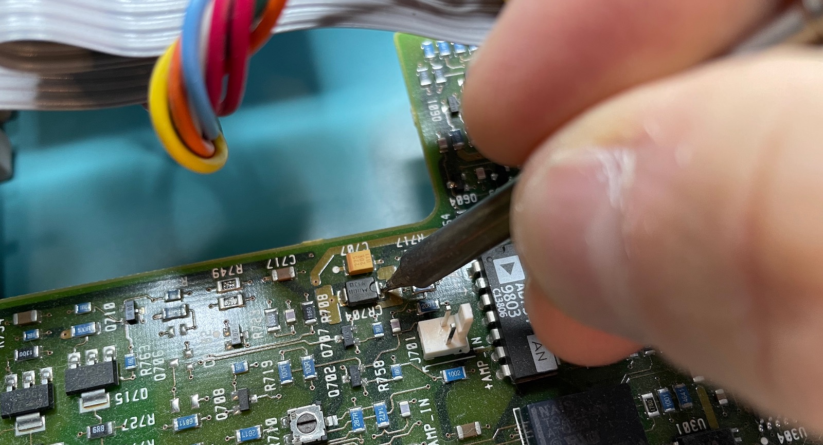
… but while the -15V rail was now reading the right voltage, the output of the function generator was still a flat line.
Staring at the Eye of Sauron
I once again started probing all around the PCB to check if anything else might be wrong.
Tip: if you’re probing a live circuit with an oscilloscope and you set the impedance at 50 Ohm, you’ll get really weird results…
I did this for at least 15 uneventful minutes when suddenly I was staring at the Eye of Sauron:
I’ve seen magic smoke in the past, but this thing was glowing red hot! The smoke of burnt FR4 material lingered in my lungs for the rest of the day. I had my priorities straight and took a picture first before shutting down power.
There was clearly some kind of short inside the PCB, though it’s unclear why it took a while to show up. The chances of a successful repair were not looking great.
FLIR IR Imaging
How do you get rid of a short inside a PCB? You use a drill to remove the piece with the short entirely, and then you try to reconstruct the collateral damage.
But before you can do that, it’s best if you have a good idea about the exact location of the defect, and whether or not you have actually fixed it. This is where IR imaging comes in really handy.
I have a friend who owns a FLIR IR camera module. It’s not a full camera, but an extension that can be plugged into the iPhone lightning connector:
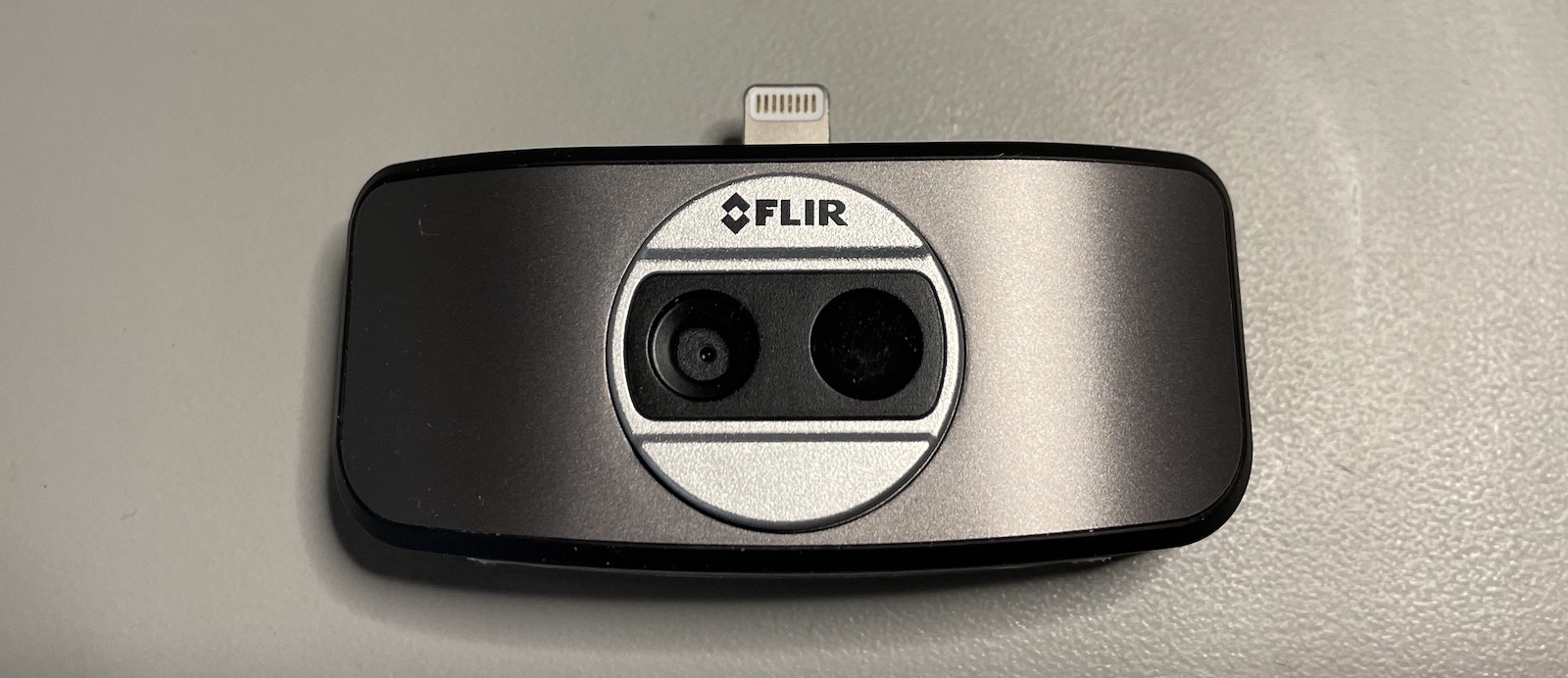
At around $300, these things are not cheap, but they’re amazing.
Here’s what happened in IR when I switched the 33120A on again:
This time, it heated up immediately. This, at least, makes it much easier to verify whether or not the issue is gone.
With a working unit in hand, I could take an IR picture to use as a reference signature image and check how things should look when everything is fixed.
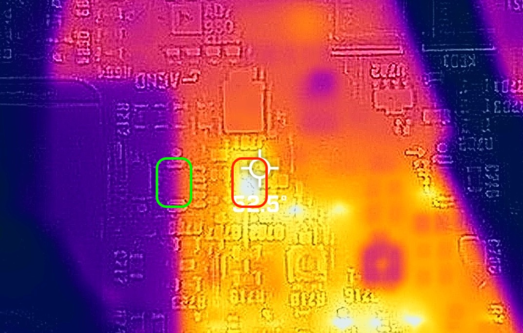
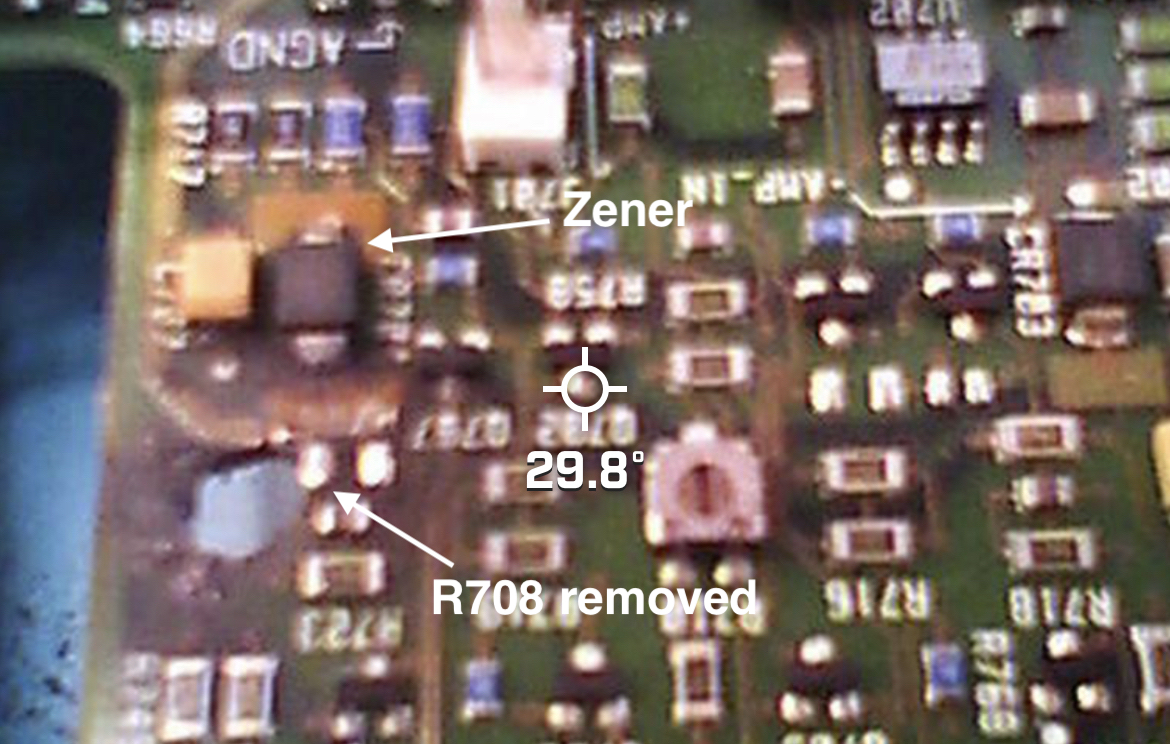
The FLIR camera overlays the IR image with the non-IR image, but the iPhone lens and the FLIR module lens are on the opposite side of the phone, and not aligned along the same axis. The FLIR software has an image shift function to correct for this, but only along 1 axis.
In the picture below, the green rectangle shows the Zener diode in non-IR while the corresponding IR image is in red. We can see that the Zener heats up to a temperature of roughly 52C, or a bit more because I didn’t quite hit the warmest spot:
To Destroy a PCB in Order to Save It
It just feels wrong to use a Dremel tool to drill a hole in something you’re supposed to repair, but here we are. There weren’t really any other options.
Here’s the situation after the first drill:
I drilled right above where C717 used to be, trying not to cut into the connections of R706.
The IR image after the first drill is much improved, but there’s still a 79C hotspot that I didn’t think should be there:
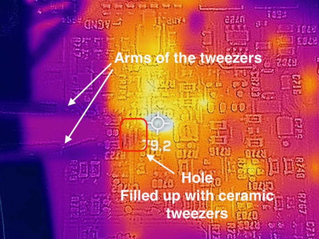
You can’t see the drill hole in the image above because I was using ceramic non-conductive(!) tweezers to better get my bearings on the IR image.
Since the hotspot was to the top-right of the drill hole, I decided to enlarge the hole in that direction. There was a high chance that I’d destroy the connection to the left of R708 in the process, but so be it. I did desolder R708 first because I didn’t have a spare 196 Ohm resistor in my component box.
Here’s the situation after the second drill:
The hole now almost touches the left pad of R708.
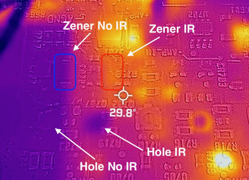
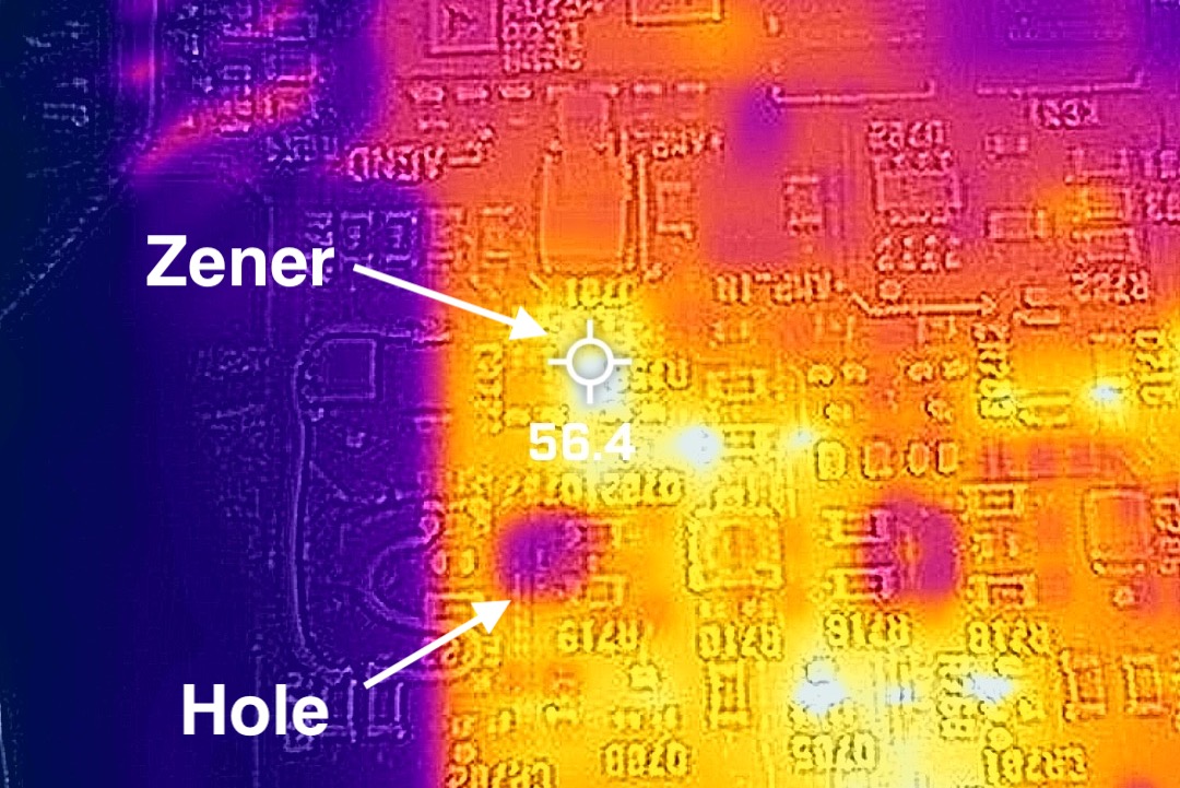
- You can clearly see the IR hole: when there’s nothing there, there’s nothing to warm up.
- There’s no 79C hotspot anymore at the top right of the hole. That’s great: the short seems to be completely gone now!
- The Zener doesn’t warm up. That can be easily be explained by the drilling: if the hole has cut off the -15V rail to the rest of the components, then no current can flow and there’s thus nothing to warm up.
After soldering R708 back, the IR image stayed the same.
Circuit Reconstruction
It was no surprise that the generator still didn’t output anything: some signals were destroyed and needed to be rebuilt. First step is to figure out what was broken. As reasonable assumption was that the broken signals would go to the nearby components.
With the help of my working 33120A, the schematic, and a bunch of probing with a multimeter, I ended up with the following interconnections:
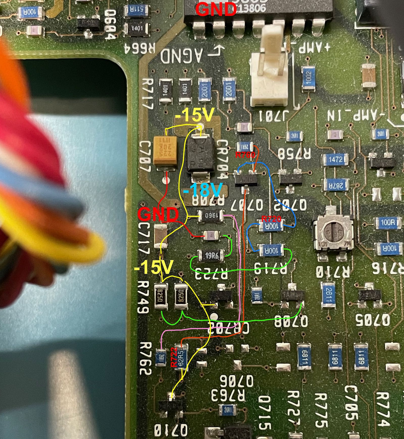 (Click to enlarge)
After measuring things on the drilled PCB, the only missing connections were the -15V rail for R708 and R749!
I didn’t not have a 2.2uF C717 replacement, but since that’s just a decoupling cap that sits in parallel with the much larger C707, it shouldn’t prevent the signal generator from generating a signal. The only potential impact might be a slight reduction in noise performance.
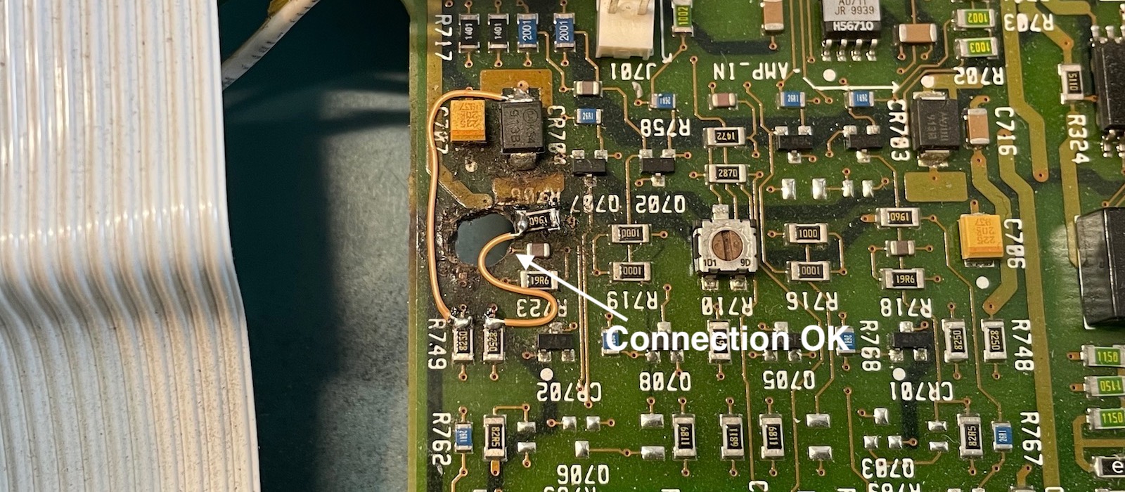
After the earlier drama, the reconstruction of the PCB is a bit of an anti-climax with just 2 wires.
Ohm-ing out the remaining connections didn’t show anything else missing. Even the connection left of the capacitor that’s sitting between R708 and R723 turned out to be fine.
Success!
Next up was the moment of truth: would the thing work now? It did!
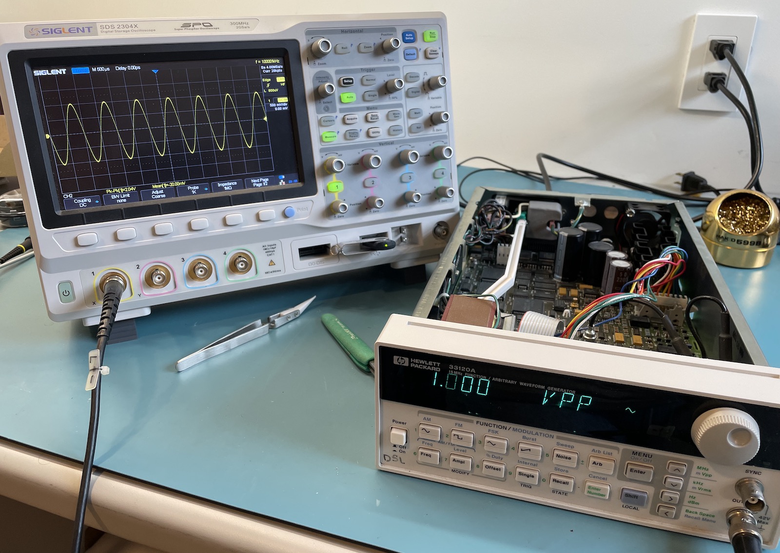
Such a rush!
Trust but Verify
All that was left was to check if everything was truly fixed.
The IR image is exactly as it should be, with the Zener at 56C, very close to the 52C that I measured on the working unit.
I also checked the signal quality by sending the output of the reference and the repaired unit to a spectrum analyzer and comparing the difference:
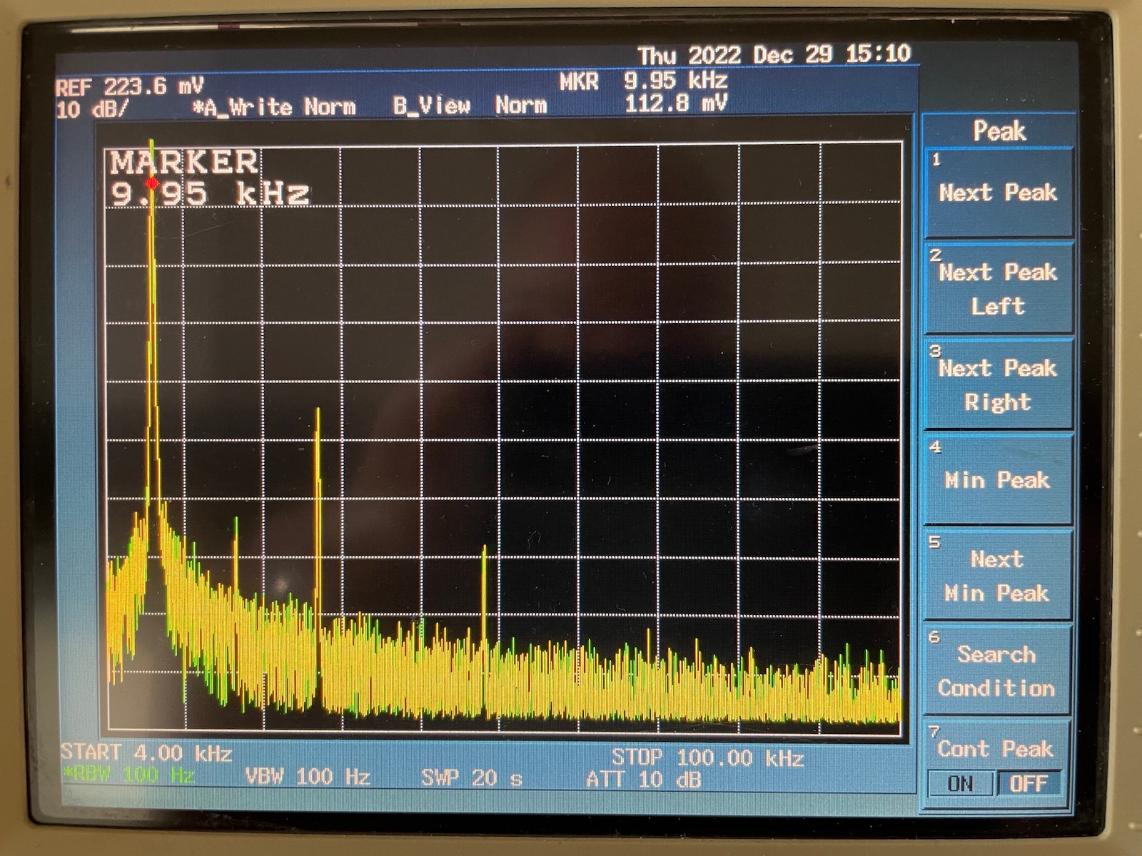
The image above shows the spectrum of a 10kHz sine wave and its harmonics up to 100kHz. Green is the result of the reference unit, yellow the repaired one. If you only see a few pixels of green, that’s because the yellow and green are overlapping almost perfectly.
I did a number of tests at different frequencies and with different waveforms: the 2 units always performed the same.
Conclusion
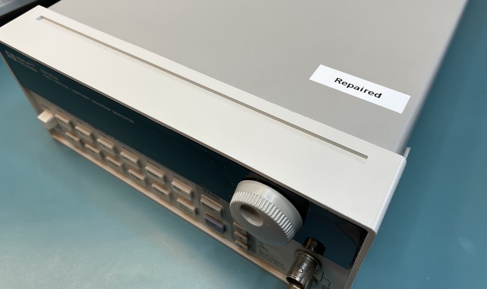
After this journey, I can officially retire the Broken label and replace it with Repaired.
The reference unit will eventually go back to the original owner, once he has a bit more space in his garage. He decided to give the repaired unit to me, so I’m now the happy owner of a signal generator. Maybe one day I’ll find a good use for it!
I would never sell the unit on eBay though. While the repair has been successful, I don’t think I’d ever trust the device enough to keep it permanently on in some kind of automated test setup. If a PCB can develop an internal short once, it could always happen a second time? I don’t want the liability of that happening to somebody else.
I totally loved the FLIR camera. I personally don’t do enough repair work to justify the $300 expense, but I can see this as an essential tool for anyone who does. The ability to see unusual stuff is amazing.
I don’t have any broken toys in my inventory for now, so on to other things to play with!