Inside an Isotemp OCXO107-10 Oven Controlled Crystal Oscillator
- The Isotemp OCXO107-10
- Gathering Information from time-nuts
- Getting It to Run
- On the Bench
- Inside the OCXO107-10
- Looking Forward
The Isotemp OCXO107-10
I spent $5 at the Silicon Valley Electronics Flea Market on an Isotemp OCXO107-10 oscillator.
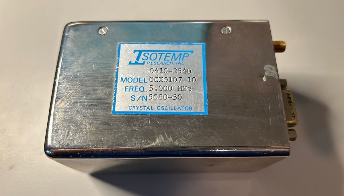
Compared to my other OCXOs, this one is a real chonker, which is often correlates with its ability to keep the output frequency stable during changing environmental conditions: a large volume gives you more real estate for tricks to keep the internal temperature constant.
Despite the -10 suffix of the product name, it has an output frequency of 5 MHz, not the 10 MHz that can be found on most equipment these days. 5 MHz used to be more popular; HP’s famous 5061A and 5071A Cesium atomic clocks have a 5 MHz output, for example, and my HP 5370A and SRS SR620 time interval counters accept both 5 MHz and 10 MHz clocks on their external reference clock input.
Gathering Information from time-nuts
I did some Google research and, to the surprise of no one, found a few scraps of information on the time-nuts email list:
- These oscillators used to cost more than $1000 a piece.
- In addition to Isotemp, CTS Knights made a product with the same 0410-2450 SKU number.
- These oscillators were used by Lucent. The CTS Knights unit has a date code of 1989, well before AT&T spun off its AT&T Technologies business unit into Lucent in 1996. My unit has a scribble of 1986.
- There’s an OCXO107-16 version which is also a 5 MHz option.
- Someone opened up his unit, did a bunch of stability measurements, and posted pictures. Those pictures have since disappeared, but I contacted the author, Ed Palmer, who graciously sent them to me.
- One of the pins of the 9-pin connector of the OCXO107 is a reference voltage that can be used to construct an EFC (electronic frequency control) input voltage to tune the output frequency. There’s apparently quite a bit of noise on this Vref output.
- There’s a datasheet for an Isotemp OCXO107-3. It’s not identical to the OCXO107-10: it has a different connector, uses more power, and there’s also mention of a 16-bit D/A converter to discipline the output frequency. But chances are that some of the characteristics are similar?
- Photo with pinout of the DE-9 connector.
That’s all I could find, but it’s more than enough to get started.
Getting It to Run
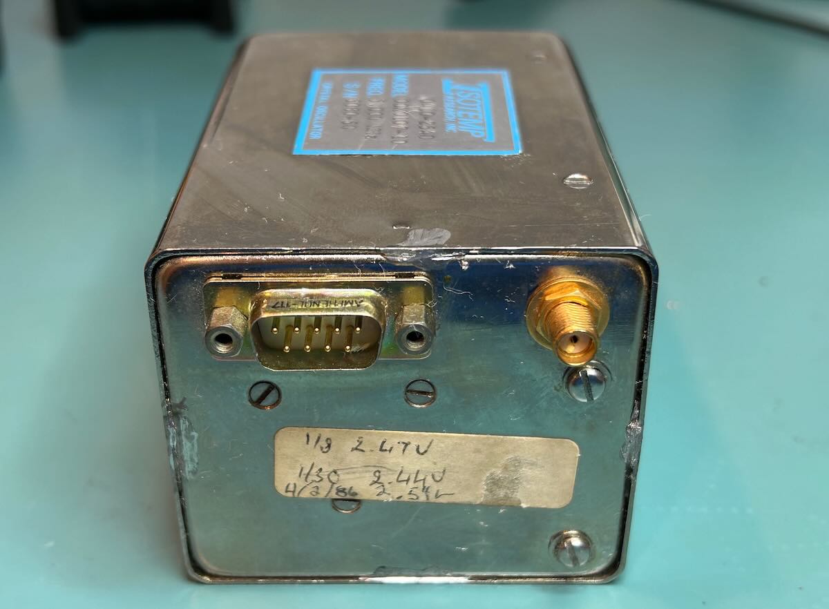
The 107-10 has DE-9 connector for power and control and an SMA connector for the clock output.
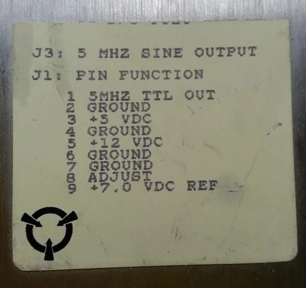
The DE-9 pinout:
1 - 5MHz TTL Out
2 - Ground
3 - +5V
4 - Ground
5 - +12V (Oven)
6 - Ground
7 - Ground
8 - EFC
9 - VREF 7.0V
The 5 V power rail is only used for the 5 MHz digital output. The OCXO will work fine and output a sine wave on the SMA port when you leave this 5 V rail unconnected.
On the Bench
I don’t have a setup to make long-term measurements, but I just wanted to see if I could get the thing to work. Here’s my earthquake-hardened bench setup:
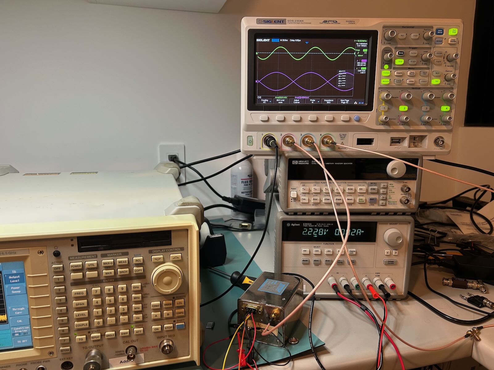
One output of an HP E3631A power supply creates the 12 V rail, the other an EFC voltage that is tuned to match 5 MHz output against the 10 MHz of my TM4313 GPSDO.
When I power up the unit, the 12 V rail initially pulls around 320 mA (3.8W) to heat up the internal oven. The current quickly drops below 100 mA and eventually settles to 69 mA (0.83 mW.)
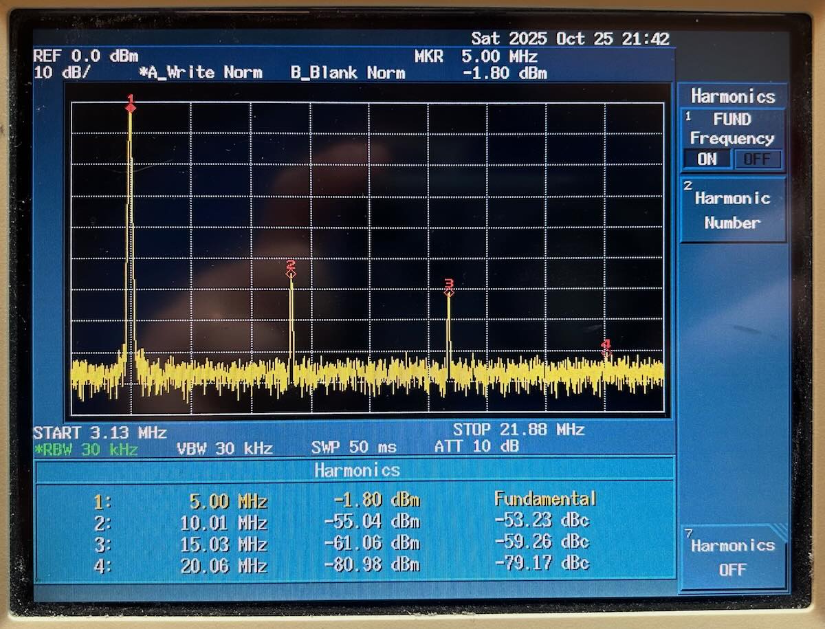
When fed into a 50 Ohm termination, my uncalibrated spectrum analyzer measures a power level of -1.80 dBm and a second harmonic of -55.04 dBm or -53.23 dBc. The output level is different than the >+3 dBm that is listed in the datasheet for the OCXO107-3, but it is similar to what others on the time-nuts list have measured.
My unit has a tag to it that says:
1/8 2.47V
1/30 2.44V
4/2/86 2.54V
This must be the voltage level that’s required on the EFC input to tune the output frequency at 5 MHz. In my current setup, that voltage level is roughly 2.228 V though that’s only 2 days after powering it up. An OCXO107-10 needs about a week to truly stablize.
The Vref output measures 6.78 V, not too far off the expected 7 V.
Inside the OCXO107-10
The OCXO has 4 solder points to weld the outside case to inside sliding assembly. I tried to get it open with a soldering iron, but the metal enclosure immediately dissipated the heat away. I wasn’t able to open my unit, but luckily Ed gave permission to use his pictures. Let’s have a look:
 (Click to enlarge)
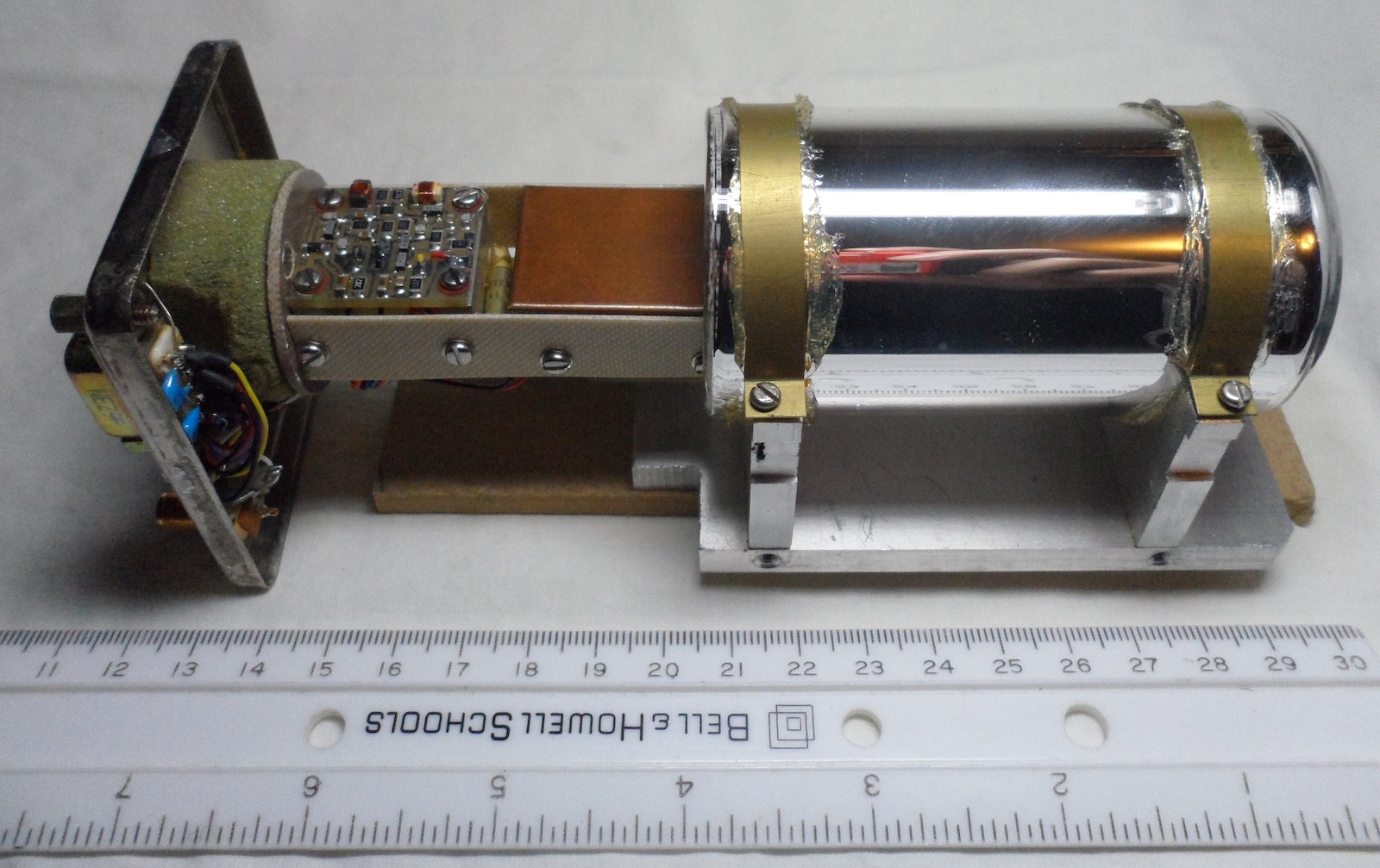
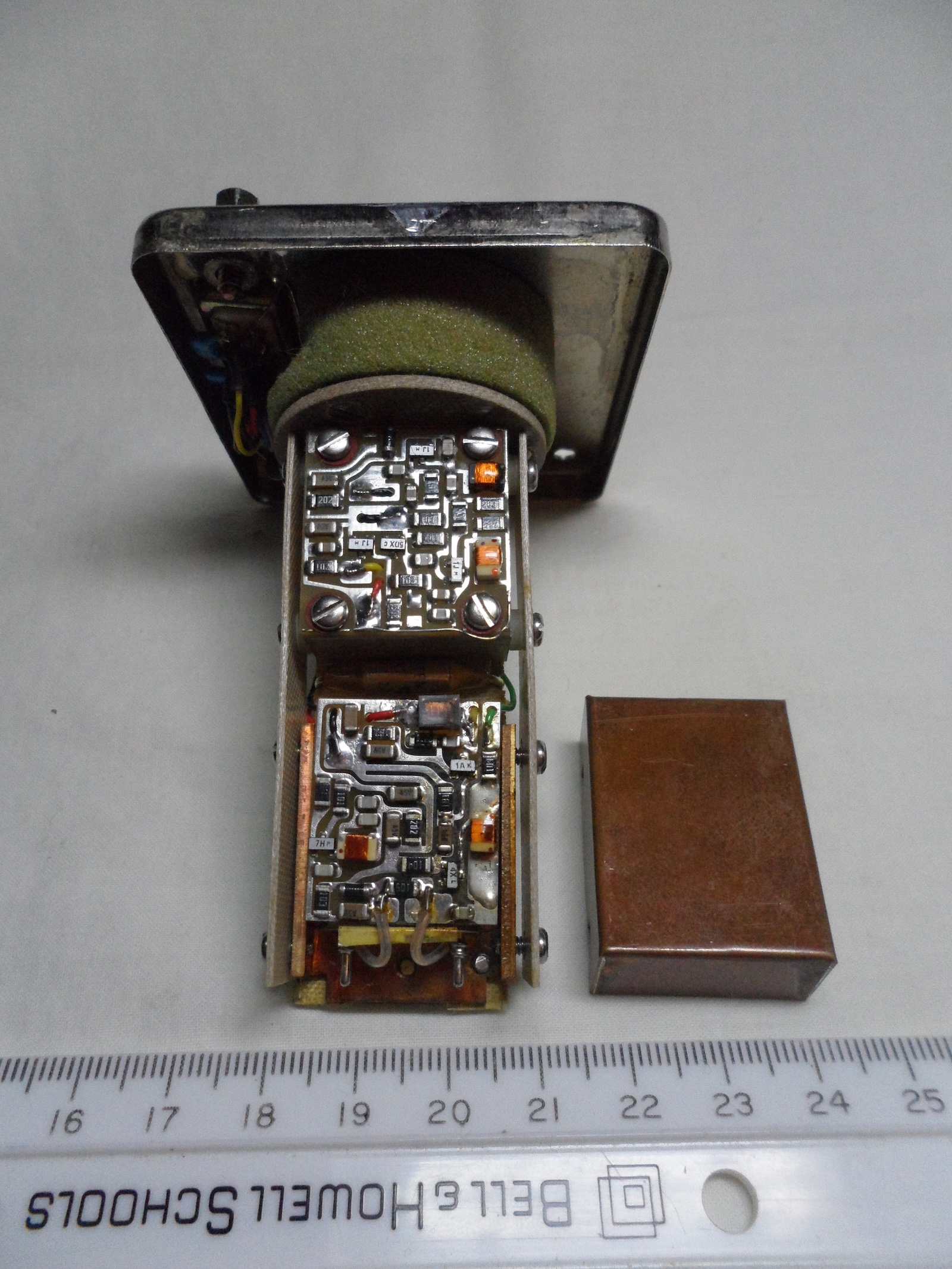
All the components of the OCXO107 reside inside a Dewar flask. Think coffee thermos with double sided wall with near-vacuum to reduce the heat transfer between the center cavity and the outside world.
In the picture above, you see the Dewar flask on the right, the electronics slided-out on the left, and an insulating foam on the far left to plug off the open side of the Dewar cylinder.
The Dewar flask makes the OCXO more resistant against varying outside temperatures, but it also makes the unit very expensive and fragile. Ed’s first unit wasn’t packaged correctly and arrived with a broken flask, which makes the OCXO useless. These days, high stability OCXOs have one or two ovens and insulating material around it, though the website of Quantic Wenzel, producer of very high performance oscillators, says that “units with Dewar flasks are still available for superior temperature performance and lower power consumption”.
I’m too much of a beginner to compare the specifications of different OCXOs but I’ll give it a try anyway, so caveat emptor. The OCXO107-3 datasheet mentions a temperature stability of < +/- 0.06 ppb for an ambient temperature between 0 C and 60 C.
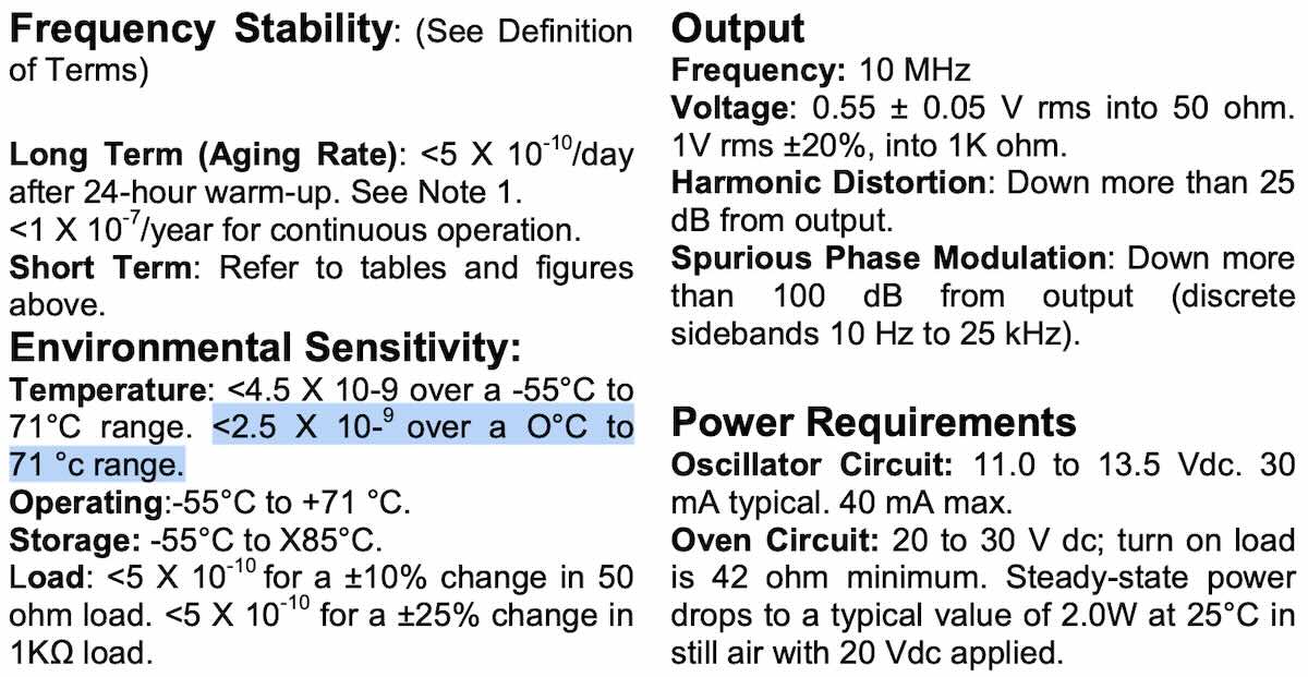
The datasheet of the HP 10811 OCXO lists a frequency vs temperature sensitivity of < 2.5 10^-9 between 0 C and 71 C. If that’s apples to apples that would make the OCXO107-3 41 times more resistant against temperature variations.
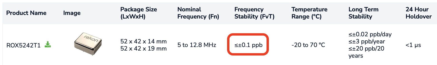
I randomly searched for specs of contemporary double-oven OCXOs and found numbers from 0.1 ppb for a Rakon ROX5242T1 and even 0.05 ppb, for units that are smaller and definitely less fragile. Just a case of old fashioned technological progress?
Note that temperature sensitivity is just one of many OXCO metrics. You also need to compare again voltage stability, phase noise and a whole bunch of other parameters, and select the one that matches your needs. For example, the temperature sensitivity of a 10 MHz lab reference clock may be more important than phase noise, while the opposite can be true for an oscillator that’s used for multi-GHz communication links.
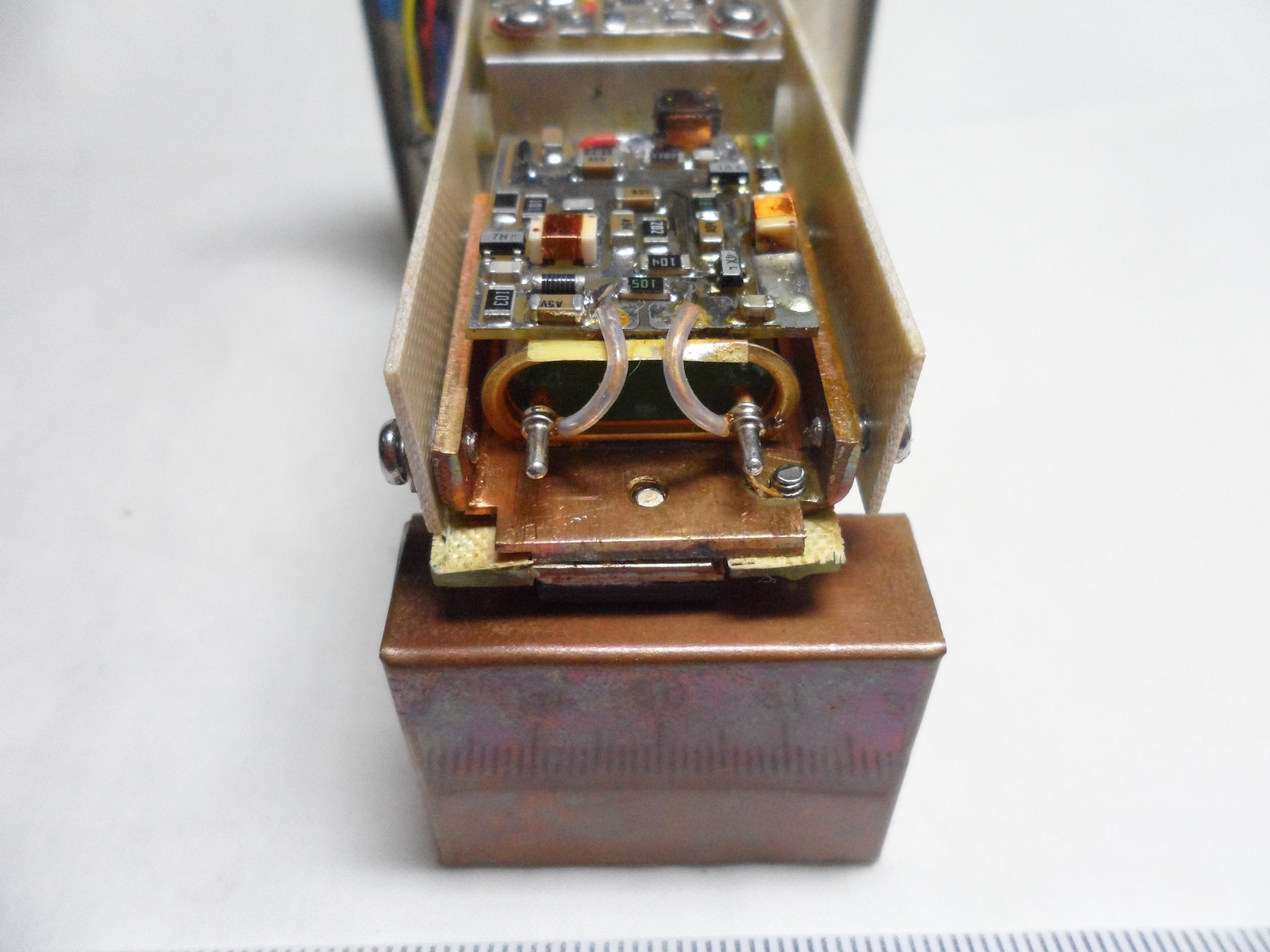
After removing the copper heatsink, you can see the oscillator control board on top of a large crystal:
 (Click to enlarge)
Here’s another view of this side of the assembly:
 (Click to enlarge)
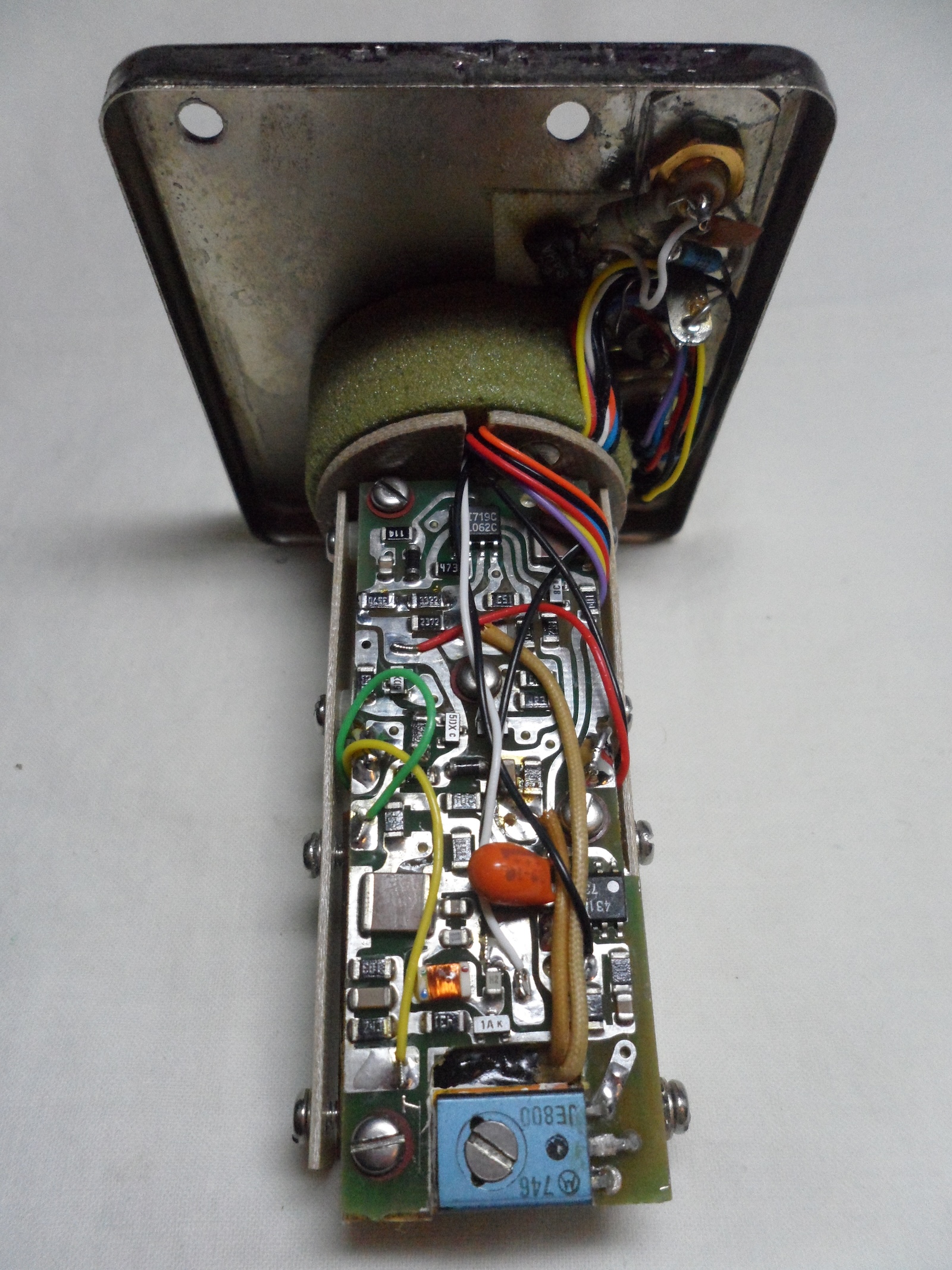
If you turn around the assembly, you see this:
 (Click to enlarge)
The blue component at the bottom is a Motorola JE800 Darlington transistor that is used as heating element. Closeby, to the right of the orange capacitor, is an IC with 431 marking. It’s tempting at first to speculate that this is a TMP431 temperature sensor, , but since those require a microcontroller to configure that’s unlikely. Maybe it’s TL431 voltage reference instead? Either way, there must be something on the PCB to measure voltage and feed that back to the heating transistor to keep temperature stable.
Looking Forward
My home lab currently has 2 clock references: the TM4313 GPSDO and the free-running GT300 frequency standard that I tore down last year. I’ve been wanting to do a bunch of long-term comparative measurements on a bunch of OCXOs, just for the fun of it. However, since crystal oscillators need a long time to truly stabilize, think a week for the OCXO107, this is not something I want to do with a power guzzling and noisy E3631A bench supply. The first step is to build a custom smaller scale linear power supply just for this purpose. In other words: yet another project to put on the stack!