Cable Length Measurement with an HP 8007B Pulse Generator
- Introduction
- Some Applications for Pulse Generators
- The HP 8007B Pulse Generator
- A Quick Look Inside
- The Most Basic Time Domain Reflectometry Experiment
- The Same Measurement on a lowly TDS420A
- Conclusion
- References
- Footnotes
Introduction
Living in the Bay Area is not all roses, but one amazing benefit is the amount of electrical engineers who are retiring, downsizing, and finally getting rid of their old test equipment. There’s John, who has my number on speed dial when he wants to get rid of signal generators, spectrum analyzers, and frequency counters. (“I know the price is way too low, but I don’t want to sell to somebody who’d just put it on eBay”), and there’s Lew who’s similarly cleaning up his lab of old but extremely well maintained RF equipment.
 (Click to enlarge)
A few weeks ago, Lew posted not one but 2 HP 8007B pulse generators on Craiglist for a total of $50, sold as a pair only. Granted, only one unit was working and the other for parts only, but Lew had already tracked down the failure to the output amplifier so it might be fixable. That’s maybe for another time…
Let’s be clear: I have no use for a pulse generator, and before writing this blog post I didn’t know what these things are normally used for either. Wikipedia tells me they are often used to create a stimulus to analyze a device under test, confirm proper operation, or pinpoint a fault in a device.
But for $50 it seems like a fun thing to play with, and it looks cool, so I made the 2 mile trek from Sunnyvale to Los Altos to pick up the units.
Some Applications for Pulse Generators
I went through a lot of documents to get a better idea about pulse generator use cases. Here are some examples, though some of them are outdated…
Cable length measurement
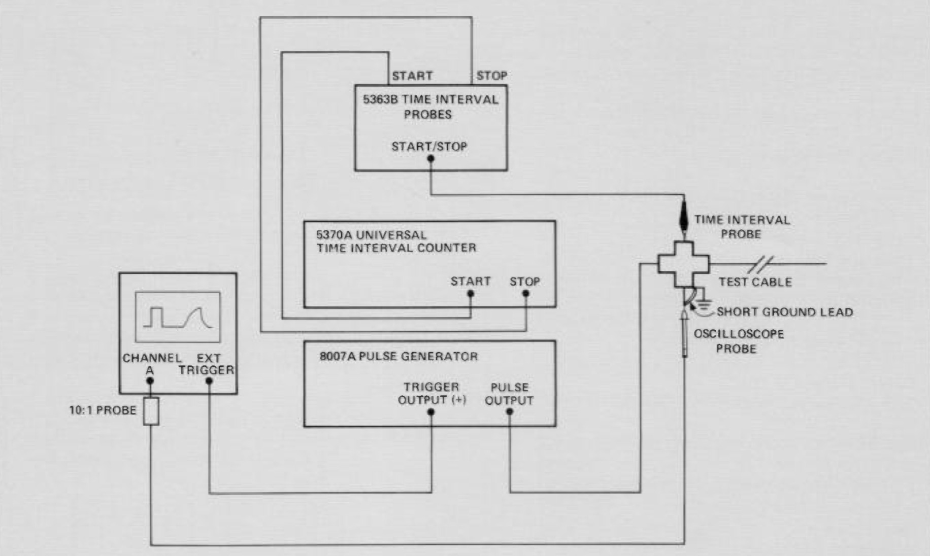
A fancy name for this technique is Time Domain Reflectometry (TDR). You send a pulse into a cable, and observe when it gets reflected back.
The diagram above is a fancy automated setup, but you can make do with just an oscilloscope.
I’ll get back to this below.
Impedance measurement of a transmission line
This is still part of the TDR field. In this case, you don’t only look at when things happen, but also what happens. As the signal travels along its transmission line, the amplitude will be different for sections with a different impedance.
This can be used to test the quality of an RF PCB (changes in thickness result in different impedance), check the quality of connector-to-PCB connection, find out where along a cable there’s a breakage (partial or not), and so forth.
For cases like this, the rise time of the generated pulse and the rise time of the your oscilloscope are crucial, since it will impact the spatial resolution of the transmission line features that can be observed. With a 16GHz oscilloscope with a 28ps rise time, you can distinguish PCB features that are smaller than 3mm. Meanwhile, a 500MHz oscillsocope with a 850ps rise time will have a resolution of only around 10cm.1
Here’s a really cool video that shows how moving your finger along a microstrip changes the impedance along the strip:
And in this article, they’re using a pulse generator to measure the impedance of Ethernet twisted pair cables.
Testing the noise immunity of TTL logic
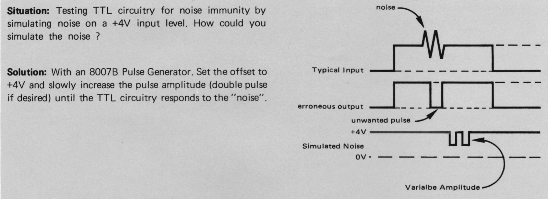
In this case, you’re creating a pulse with fixed voltage offset and with varying amplitude, you apply it to the input of a TTL gate, and you check when that TTL gate start toggling.
This can obviously also used for other logic families.
I can see how this was useful back in the early seventies when logic families were starting to become popular, but it’s not very relevant today.
Measuring the sensitivity of a flip-flop
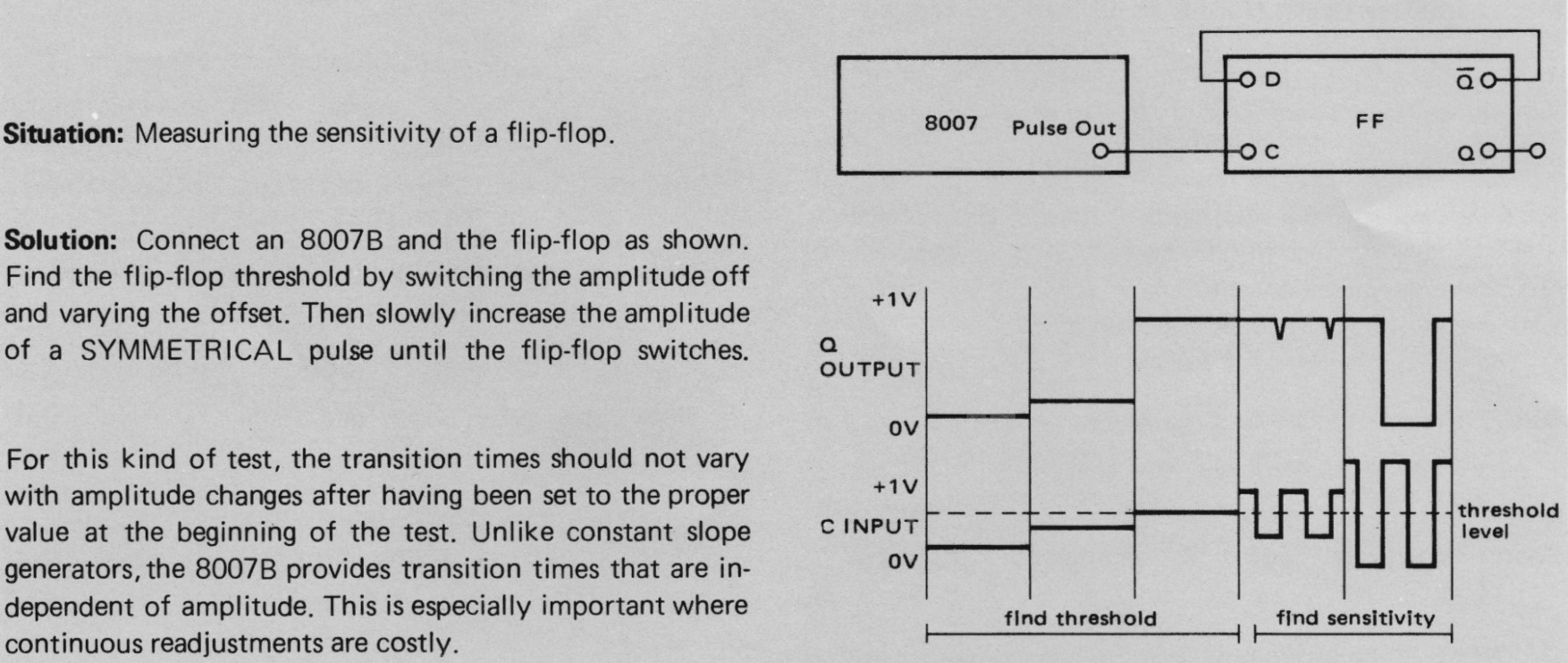
This use case is quite similar to the previous one, except that you’re now testing the threshold of the clock of a flip-flop.
Testing the threshold voltage of digital logic
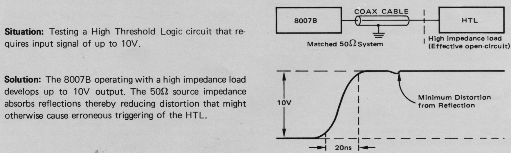
The example above is for High Threshold Logic (HTL), a logic family with much higher voltages that the 5V, 3.3V and 1.2V levels that we’re seeing today. It is (or was?) used for industrial equipment.
The idea is once again the same as above: use the pulse generator test logic voltage level and noise sensitivity.
For example, I’ve used the pulse generator to see if it’s possible to use LVDS inputs of an FPGA as voltage comparator.
Testing the bandwidth of lab equipment and probes
One common feature of pulse generators are the ability to generate edges with a very short rise time. This makes them useful to test the bandwidth of oscilloscope probes.
If you feed a pulse with a very short rise time into an oscilloscope with a larger rise time, the output will be the pulse with the larger rise time. There’s a rule of thumb to convert from rise time to oscilloscope bandwidth:
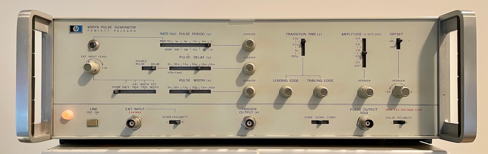
\[BW(Hz) = 0.35/rise\ time(s)\]The HP 8007B Pulse Generator
I don’t know the exact date when the 8007B came to be, but the manual was printed in October 1972, which makes it more than 50 years old.
Here’s some information I’ve been able to gather on the web:
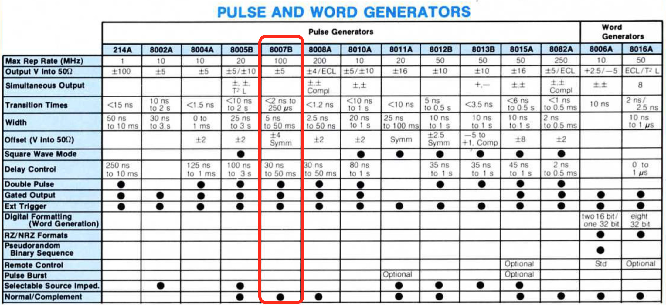
An HP Pulse Generators catalog contains a few bullet points and a pulse generation comparison table:
For a bit more detail, you can turn to page 287 of the huge 1976 HP general products catalog which has a nice one-page spec sheet. It also lists a price of a cool $2000!
As usual, Keysight still maintains an 8007B product page which has the operating and service manual, but the scan quality is not great. I decided to splurge on a high quality scanned copy at ArtekManuals for $12.2
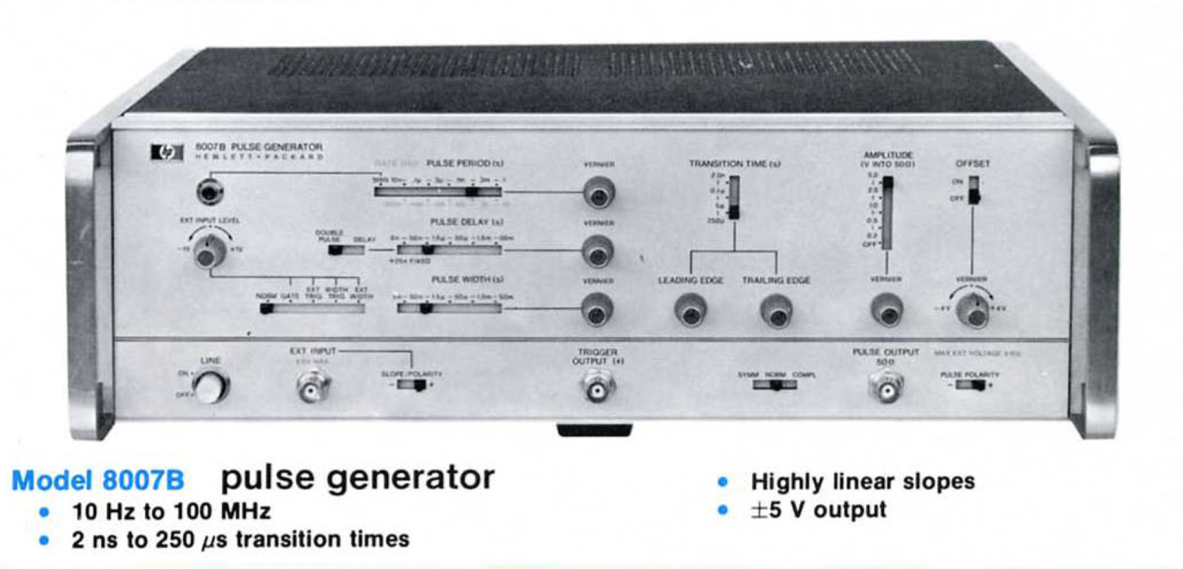
Here are some of the key features of the 8007A:
- 10Hz to 100MHz
- 2ns to 250us transition times
- highly linear slopes
- up to ±5V output into a 50 Ohm load
- pulse delay control from an external trigger
Of those, a transition time of 2ns is probably the one that is hardest to get with run-off-the-mill signal generators that you can find in a lab. For example, fastest rise time of my HP 33120A signal generator is a whopping 40ns.
That said, a Leo Bodnar Pulse Generator generates pulses with a 40ps rise time for just $70.
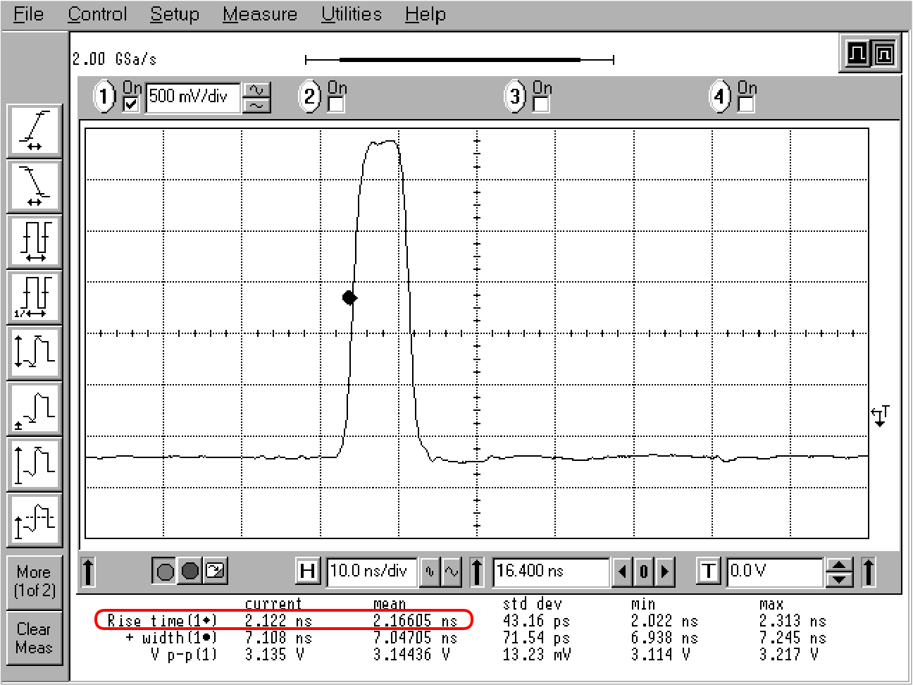
Let’s connect the pulse generator an HP Infiniium 54825A, a 25 year old but still very capable oscilloscope with a 500MHz bandwidth and a 2 GSa/s sample rate. The datasheet lists a rise time of 700ps, but a footnote says that this number is derived with the 0.35/bandwidth rule of thumb.
 Click to enlarge
We can see a rise time of 2.1ns, a pulse width of 7.1ns (it can be made shorter), and a peak-to-peak voltage of 3.1V. In this measurement, the oscilliscope is configured with a 50 Ohm termination to match the source impedance of the pulse generator.
With these formulas and a rise time of 2.1ns, we get a bandwidth of 166MHz, so we can be pretty sure that we’re nowhere near to being limited by the bandwidth of the 500MHz oscilloscope. I’m using a coax cable here instead of a probe, so there’s no need to worry about bandwith limitations of a probe either. In other words, we can be reasonably sure that the measured 2.1ns is accurate.
A Quick Look Inside
I haven’t done an in-depth teardown of the 8007B yet, but here’s a quick look inside.
The top:
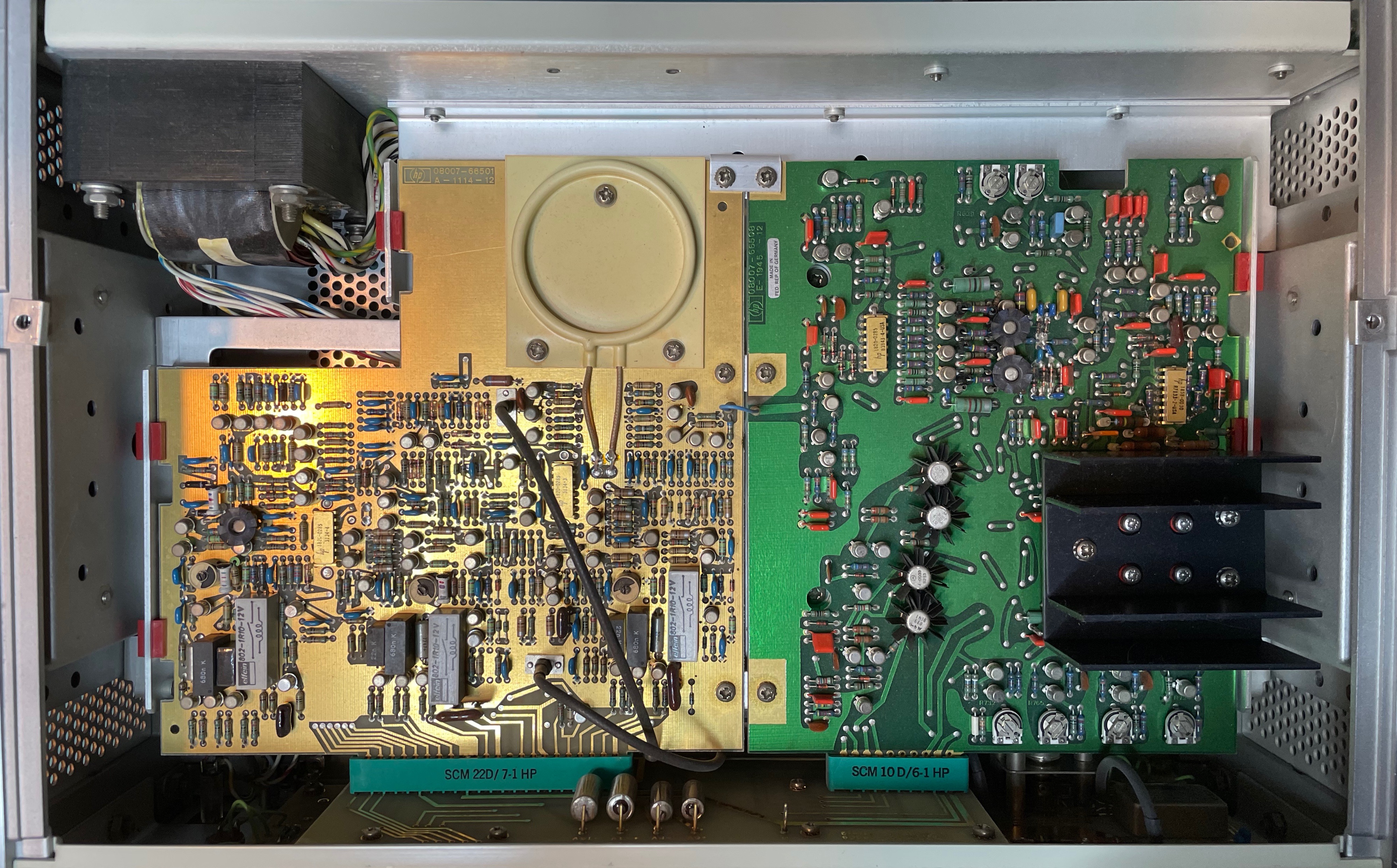 Click to enlarge
One thing that I find really cool in the picture above is the ring. Marked “DL2”, it’s a delay line. There’s a second one on the other side of the same PCB, but it’s hidden behind a different PCB.
The design is almost entirely built out of discrete components with a few custom ICs. I’ve yet to find the 2 delay lines in the schematic.
The bottom:
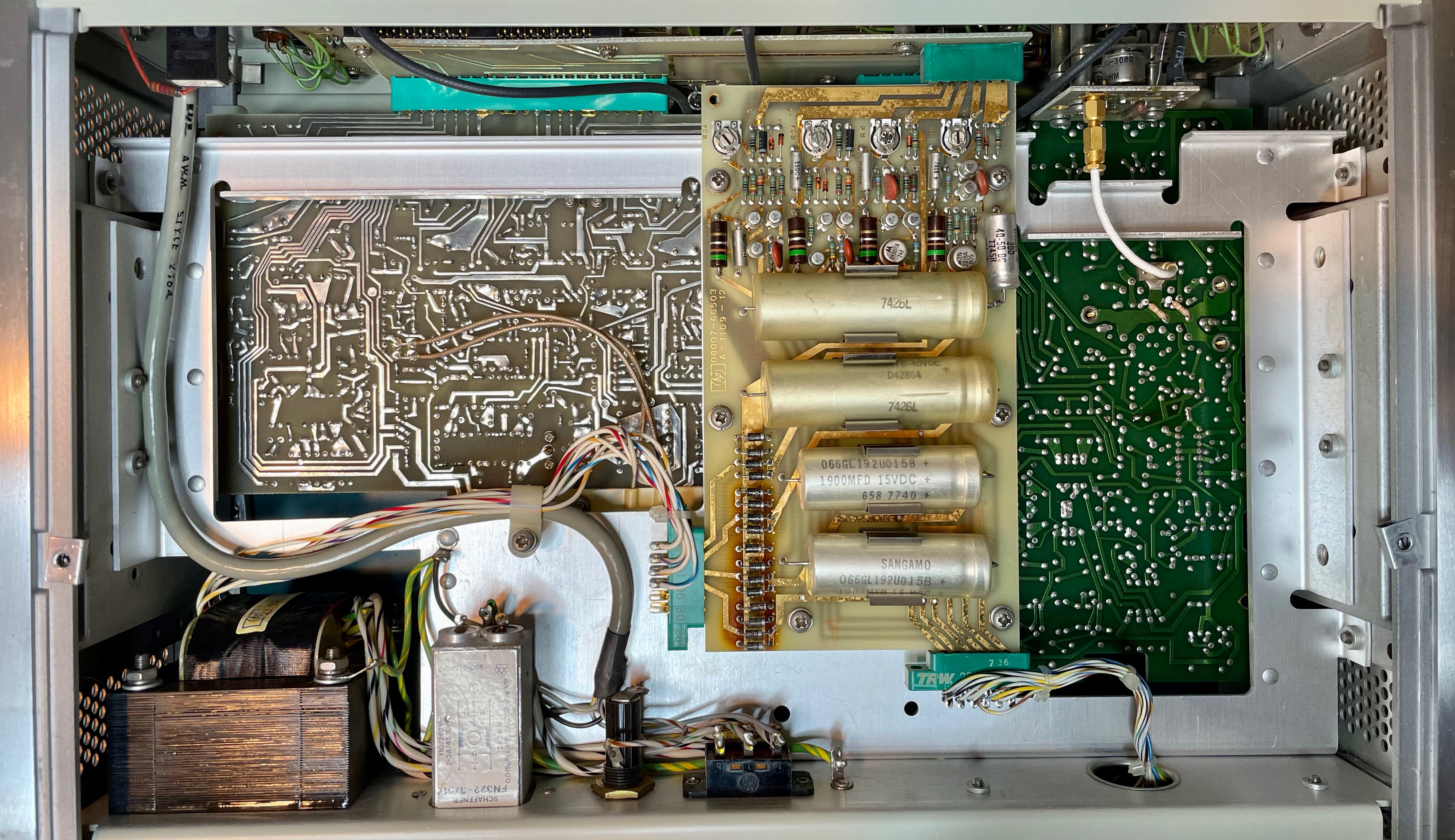 Click to enlarge
You should check out this amazing 8007B repair, where the author recreates one of the custom ICs from scratch.
The Most Basic Time Domain Reflectometry Experiment
I’m not very good with analog electronics and RF, so I decided to use the pulse generator get more familiar with characteristic impedance, reflections, coax cables, and RF probing.
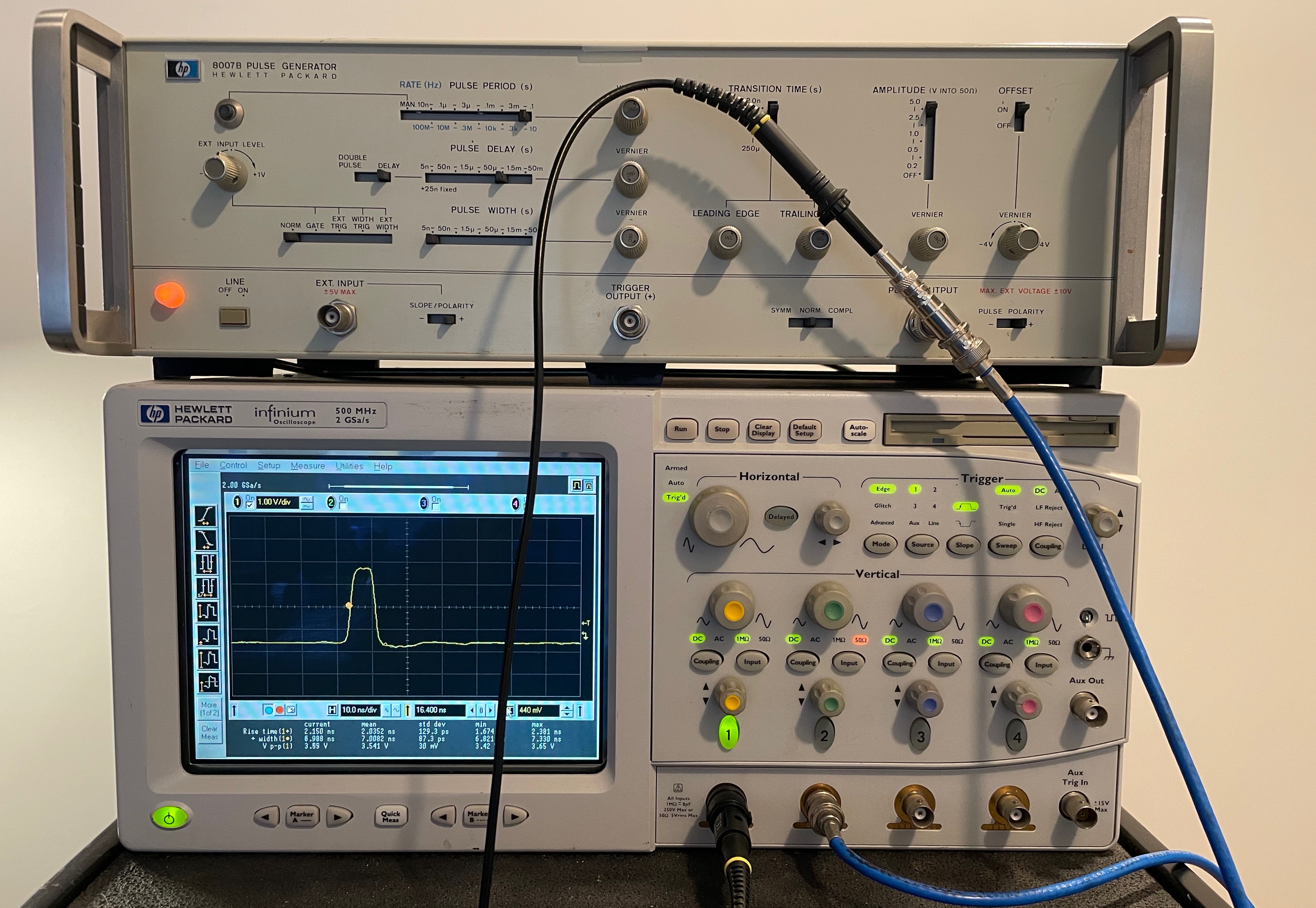
My setup was really simple:
- the 8007A pulse generator driving a BNC splitter
- the HP Infiniium oscilloscope
- a probe that records the signals at the pulse generator source
- a coax cable that connects the other side of the BNC splitter to channel 2 of the oscilloscope
That’s really all there is to it!
Here’s a picture of the setup:
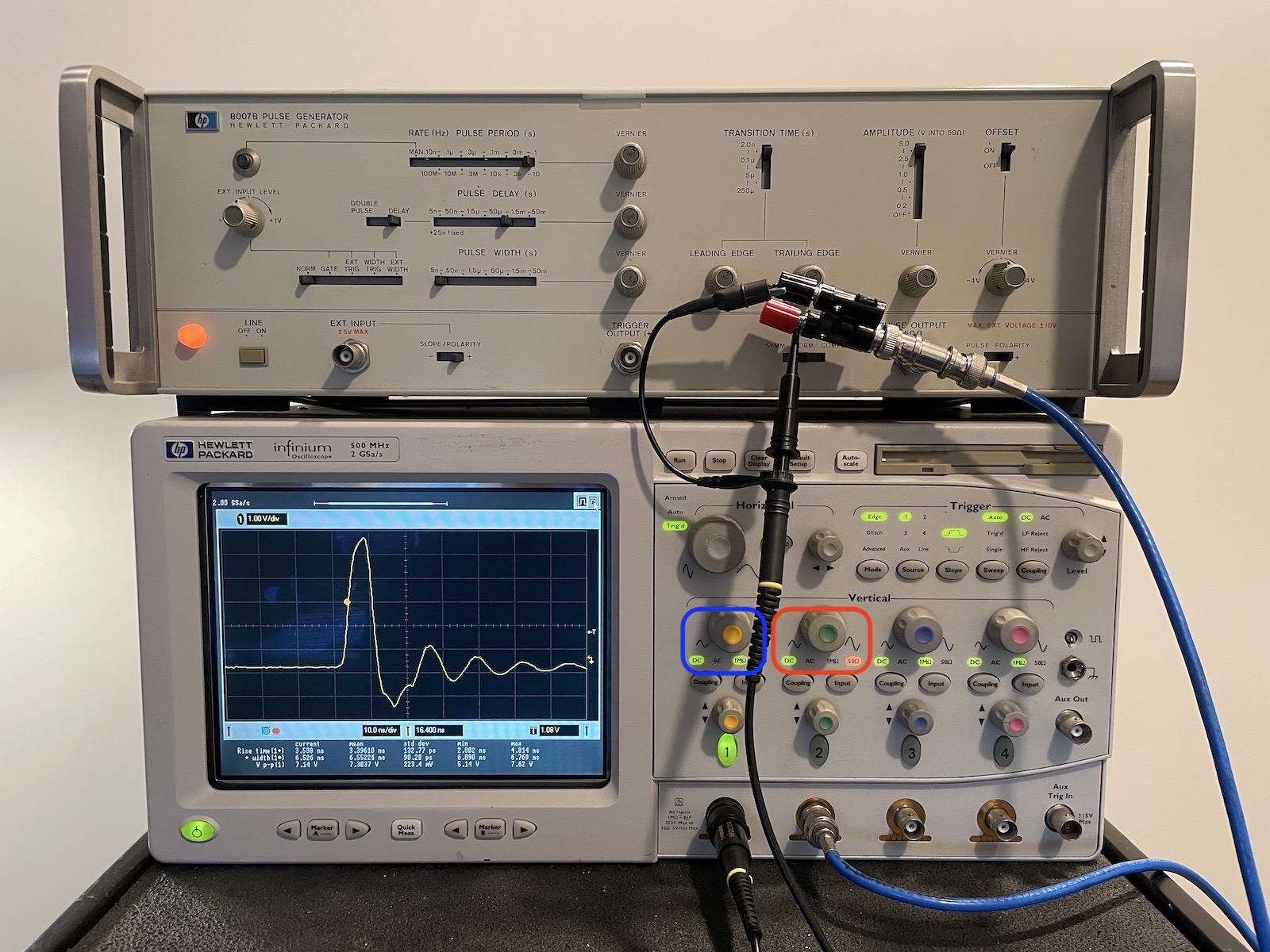 Click to enlarge
A few things to note here:
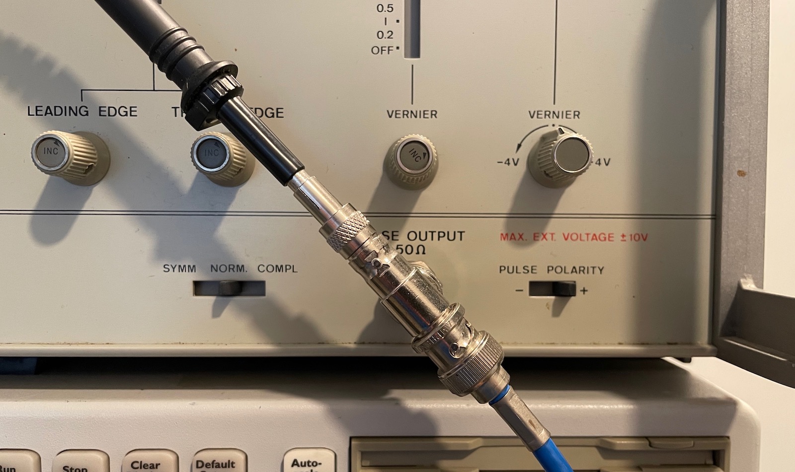
- channel 1 of the scope is connected to a regular capacitive 10:1 probe, so it has a termination of 1M. (Check the right green indicator in the blue rectangle.)
- channel 2 of the scope has the coax cable. It has a termination of 50 Ohm. (See the right red indicator in the red rectangle.)
The 50 Ohm termination matches the source impedance of the pulse generator and characteristic impedance of the coax cable. There should be no reflections. The scope is showing the signal that’s measured by probe, but it has horrible ringing!
The reason for this is the crappy setup at the source, with a horrible plug that’s connected to the BNC splitter, and a probe that uses a long ground wire which introduces a good amount of induction to the circuit.
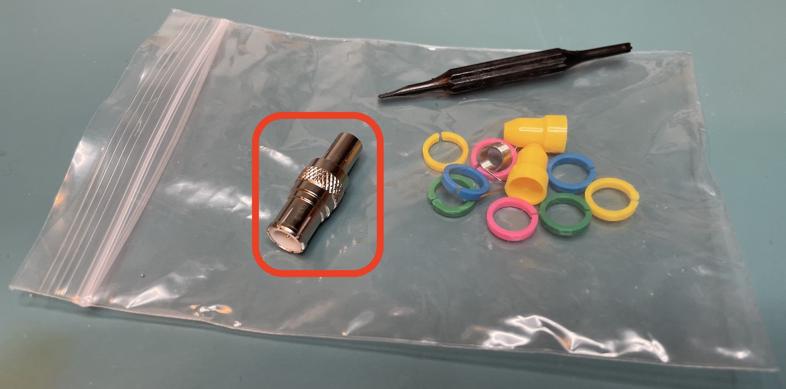
This is the moment where I finally figured out the use of that metal gizmo in the goodie bag of my oscilloscope probe: it’s a probe BNC adapter!
And it does wonders to the quality of the signal:
 Click to enlarge
Let’s now switch the termination of channel 2 of the oscilloscope from 50 Ohm to 1 M. (You can also just disconnect the cable from the oscilloscope.) The pulse that’s traveling down the cable will see a mismatching impedance and will reflect back to the source, resulting a second pulse a bit later. And indeed:
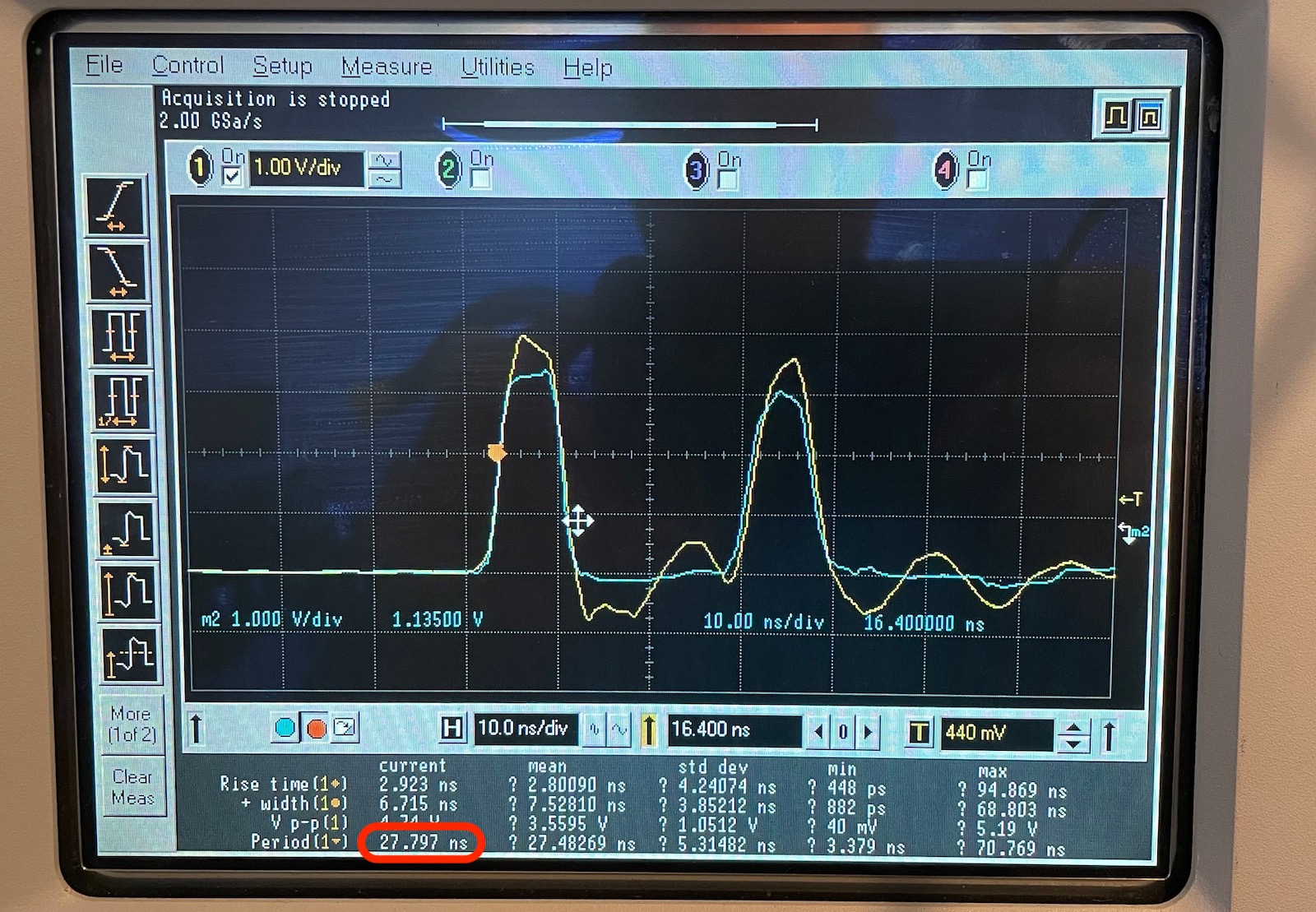
In the image above, the yellow signal are the pulses measured without the probe BNC adapter, the blue signal with adapter.
The scope measures a time of 27.8ns between the rising edge of the two pulses. We can use this time to calculate the length of the cable with the following formula:
\[length=\frac{speed\ of\ light \cdot measured\ time}{2}\]The speed of light in a coax cable is around 0.65 of the one in a vacuum. And we’re dividing by 2 because the signal needed to travel both ways.
\[\frac{0.65 \cdot 300 \times 10^6 \cdot 27.8 \times 10^{-9}}{2} \rightarrow 2.7m\]Which is indeed the length of the cable.
The Same Measurement on a lowly TDS420A
That Infiniium scope is a ‘permanent’ loaner from a friend, and a pretty high-end oscilloscope by today’s hobbyist standards. I repeated the measurments with my lowly TDS420A oscillscope. It’s rated at 200MHz and just 100MS/s. How can one possibly measure events that happen in the nanosecond range on a scope like this?
The trick is that a TDS420A supports equivalent time sampling.
For repetitive signals it keeps on sampling the signal at random so that, over time, the signal gets reconstructed with a much higher resolution. In the case of a TDS420A, that higher resolution is equivalent of sampling at 5GS/s!
Here’s that same pulse as before. After 15 acquisitions, you start to see the outline of the pulse:
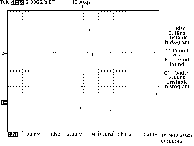
And after a few hundred acquisitions, you end up with this:
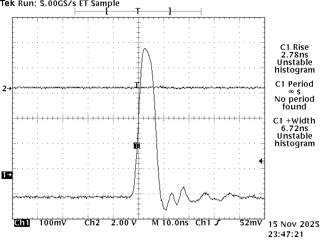
Here’s the result of the cable length measurement.
The top signal is at the other side of the coax cable. The bottom one is the reflected signal at the source.
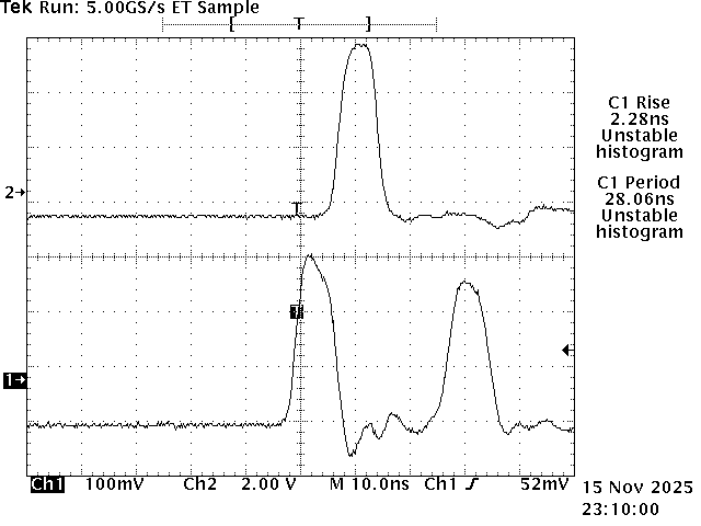
The scope measures a rise time of 2.3ns and a delay of 28ns between pulses.
The ringing on the bottom signal is because I took that screenshot before discovering the probe BNC adapter.
Conclusion
Pulse generators aren’t commonly found on the bench of a hobbyist. When I need something to trigger a circuit, it’s usually in the context of working with an FPGA and then it might as well generate that pulse with that FPGA.
But I liked how playing with one guided me into learning about rise times, probing fast changing circuits, time domain reflectometry, and cable impedance and more. It’s just so much easier to retain information by actually doing them.
I don’t suggest actively looking for a pulse generator, but if you can find one (or two) for cheap and you have enough storage space left in your garage, give it a try.
References
- Reverse-Engineering an IC to fix an HP 8007A Pulse generator
- Curious Marc - HP 8082A Pulse Generator
- HP Magazine 1973 - 8015A: A Pulse Generator for Today’s Digital Circuits
- HP Memory Project - Evolution of the Pulse Generator Product Line during the 1960s & 1970s
- Agilent - Fundamentals of Time Interval Measurements
- HP Memory Project - Precise Cable Length and Matching Measurements
Footnotes
-
These numbers come from a discussion I had with Andrew Zonenberg on Mastodon. ↩
-
ArtekManuals is allowed to distribute these manuals under license from Keysight. Purchased copies can not be shared with others. ↩