The Agilent/HP E3631A Power Supply Repair that Wasn't
- Introduction
- Verifying the Goods
- Schematic of the 25V/-25V Power Supply
- Schematic of the Analog Multiplexer and ADC
- Measurements on the Bench
- The Solution
- Conclusion
- References
Introduction
I was browsing Agilent power supplies on eBay, as one does, and ran into the following listing:
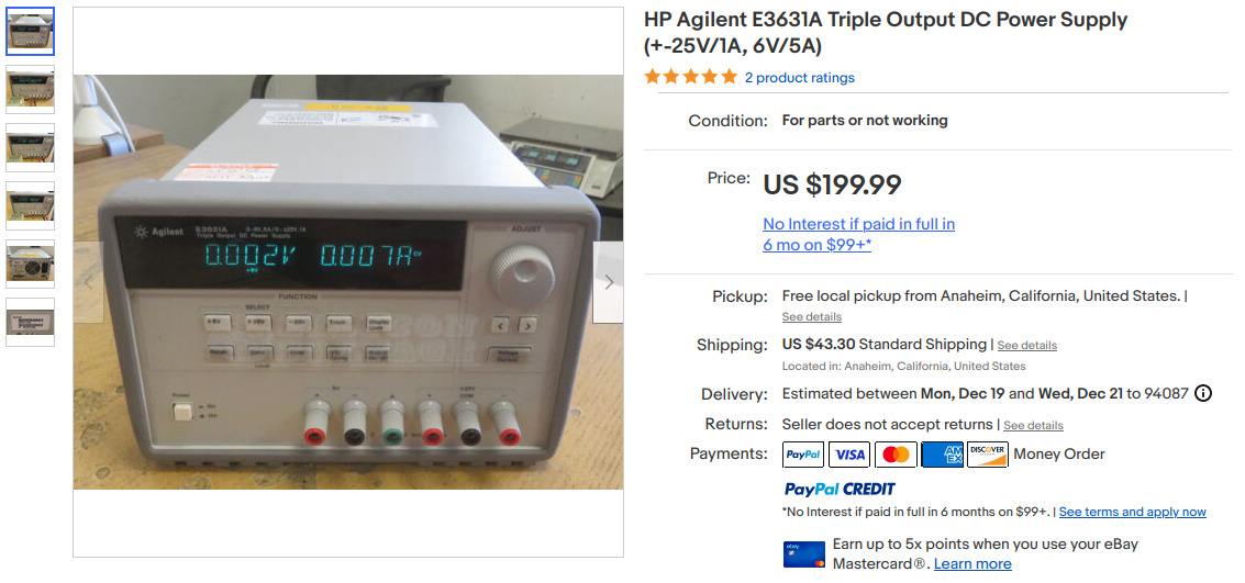
$199 + $43 shipping + tax for something that’s listed as “For parts or not working” is, believe it or not, a pretty good deal of an E3631A.
I already have an E3631A. After repairing its rotary knob, it has a permanent place on my lab bench, wired up for PC control over GPIB. It’s an excellent power supply.
The eBay listing had the following in the description:
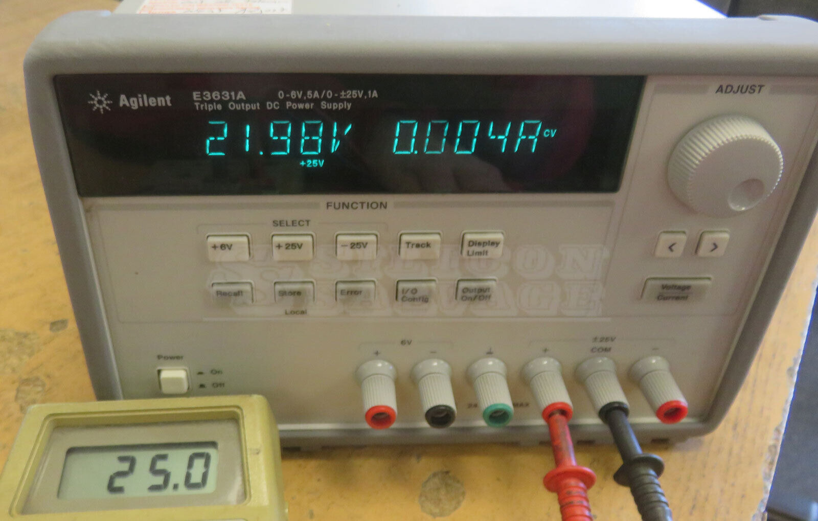
Used, powers up, displays voltages shown, at 25V it only displays 21.98V but the meter displays 25V, same with the -25V, untested any further, sold AS-IS for parts or repair.
There was also the following picture (and a near identical one of the negative 25V):
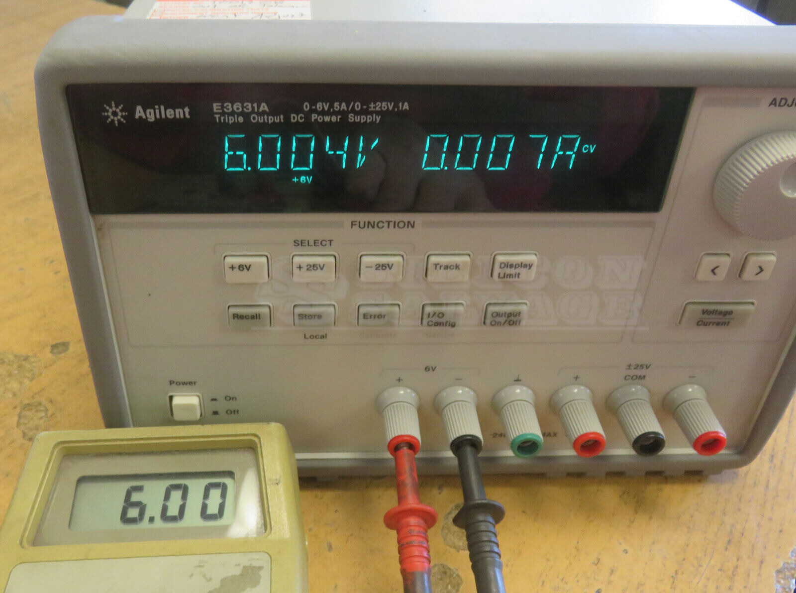
Meanwhile, the 6V rail was fine:
Let’s think this through:
- the 6V output seems totally fine.
-
the 25V and -25V are outputting 25V and -25V according to the external multimeter, but the internal read-out is wrong, showing 21.98V and -21.95V respectively.
This means that the voltage and current control loop is likely working fine, and that only the path from the output back to the microcontroller is broken.
- I knew from my earlier repair that the E3631A is built almost entirely out of off-the-shelve discrete components.
What are the chances that this will be a difficult repair? How hard could it really be?
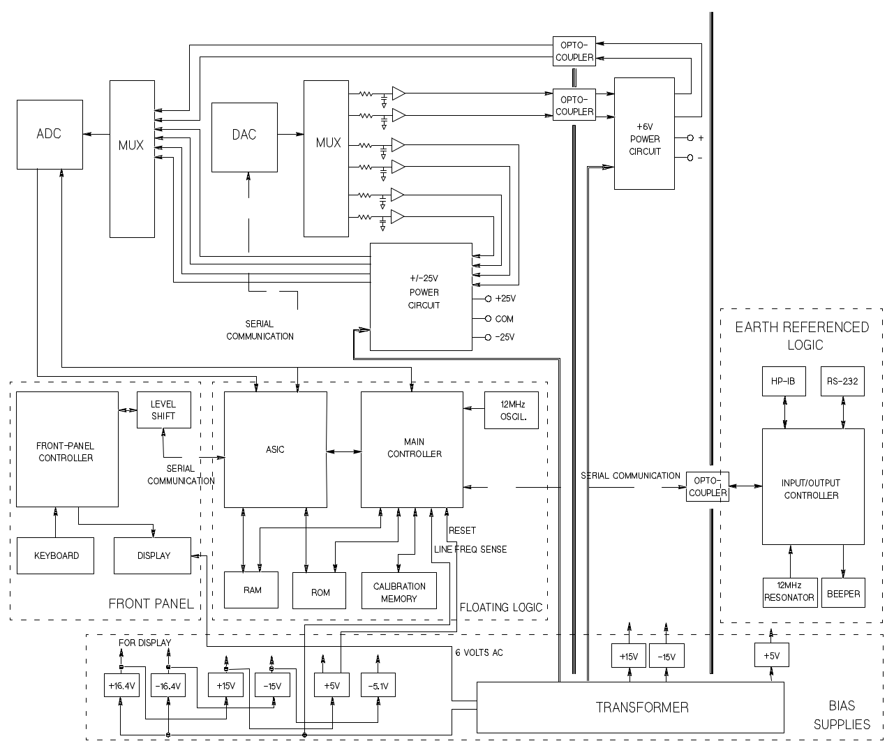
A closer look at the service manual strengthened my believe that this could be pretty easy:
 Click to Enlarge
In the top right corner, you can see that there’s only 1 DAC and 1 ADC, with multiplexers to drive and read back analog values. If the 6V rail is working, then the error should be isolated the section between the power supply output for the 25V/-25V rails and the ADC. In other words: the analog multiplexer.
I decided to take the plunge and place the order. The unit arrived just before dinner today, about a week earlier than expected. Hurray!
Verifying the Goods
Like my other E3631A, the unit was in excellent cosmetic condition. The vacuum fluorescent display is in great shape as well, as expected based on the listing pictures. Unfortunately, it only has the front bumper, but I knew that going in. Replacement bumpers are ~$35 on eBay, which feels a little high.
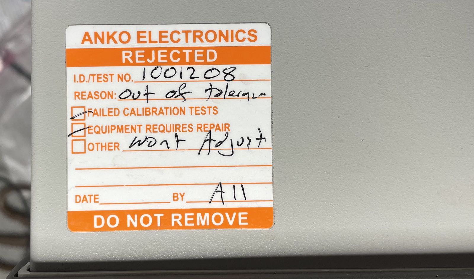
A sticker on top says:
- Rejected - Out of tolerance
- Failed calibration tests
- Equipment requires repair
- Won’t Adjust
The unit behaved as described:
- 6V working great
- read-out of 25V and -25V always 13% lower than the actual value
I checked current control with a resistor, and that seemed to work fine for all 3 outputs. Yay!
Schematic of the 25V/-25V Power Supply
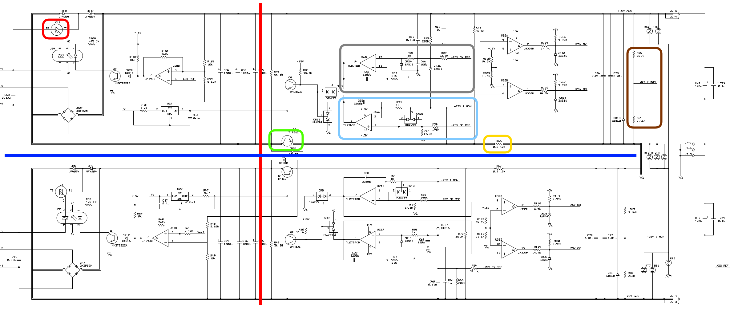
Here’s the annotated schematic of the 25V and -25V power supply. Because everything is built from discrete components, it looks quite complicated, but except for a pre-regulator it’s fairly conventional:
 Click to Enlarge
I’m not a analog designer and can’t explain all the details, but here’s my rough understanding:
The top half creates the 0V to 25V output, the bottom half 0V to -25V. Both halves are nearly identical, so I’ll only look at the top half.
The Pre-Regulator
Left of the red line is the unconventional part: the pre-regulator.
The E3631A is an old-school linear power supply, as opposed to a switched power supply. Almost all modern electronics use switched power regulators these days (except, sometimes, for the very last step to go from, say, 5V to 1.2V).
The reason for this is that switch power regulators are very power efficient but their output is often a lot noisier which is something you really don’t want in a lab setup. So linear power regulators have a cleaner output but consume more power the larger the difference between the DC voltage at the input, and the desired, regulated, voltage at the output.
If the power supply has a DC voltage that is a bit higher than 25V at the input, but the output is programmed to, say, 1V, and the output current is 1A, then the regulator itself will burn up 24W of power to feed a load that only consumes 1W. That’s a bit excessive…
Normal power supplies have a diode bridge to rectify the AC after the transform to DC. This one has that too. (It’s at the bottom left in both halves.) But what’s special here is that there’s also a triac, marked in red, that, under low output voltage circumstances, applies only a part of the AC sine wave to the rectifier. This way, the averaged rectified voltage across the 3 1000uF capacitors that are left of the red line is (pre)regulated to be lower.
I haven’t analyzed the circuit in detail, a Spice simulutation would provide more clarity, but I believe that the triac is being used as a dimmer.
The Power Transistor
Marked in green is a traditional power transistor that acts as a variable resistor to keep the voltage or the current at the desired level.
Voltage or current, because like all good lab power supplies, the user can set both power or current limits. When the current is lower than the limit, the output voltage is regulated to the programmed voltage. Otherwise, the voltage is lowered until the desired current is reached.
Voltage Control
The area in gray is the voltage control. The left side of the rectangle has +25V_CV_REF which
is a signal that comes from the DAC. It specifies the programmed voltage limit.
The reference value is compared against the actual output voltage value and a difference
is used to increase or decrease the resistance of the power transistor.
Current Control
The light blue area is the current control. It’s not super obvious, but it measures the voltage
difference between the left and the right side of the 0.2 Ohm 10W shunt resistor that’s circled
in yellow. Just like the voltage control part, the +25V_CC_REF signal contains the user
specified current limit.
Output Voltage Measurement
Marked in brown on the left, are just 2 resistors that form that divide down the output voltage.
Not particularly interesting but what if I tell you that the signal in the middle,
+25V_V_MON is the one that goes to the ADC multiplexer?
If there’s something wrong with the read-out of the 25V line, one can expect this signal to be wrong. At least, that’s what you’d think if the +25V and -25V behaved differently.
But they don’t! What are the chances that resistive dividers are broken for 2 completely separate power circuits? Maybe there’s something later that’s common?
Voltage Control vs Current Control
Not marked on the schematic, but the 2 comparator opamps to the right of the voltage and current control sections just create a digital signal to tell the microcontroller whether the regulator is in voltage or current control.
Schematic of the Analog Multiplexer and ADC
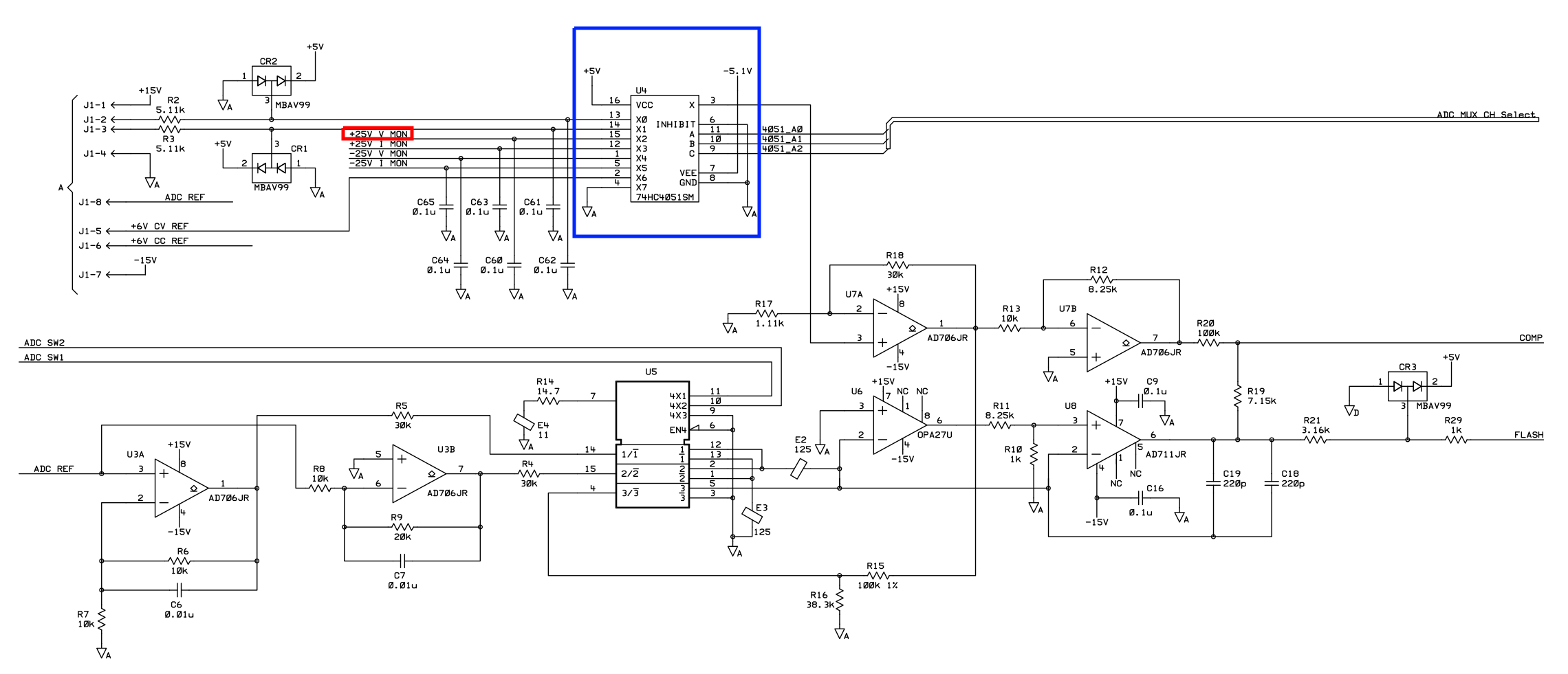
Let’s track that +25V_V_MON signal through the multiplexer and the ADC:
 Click to Enlarge
Remember how the ADC should be fine because it’s also used for the 6V output? Well, there’s nothing
else other than a 74HC4051 analog multiplixer IC, marked in blue, and nothing before that: both
+25V_V_MON and -25V_V_MON are connected straight to the multiplexer input. It is once again
extremely unlikely that 2 inputs of the multiplexer are broken (how?) while the others work fine.
As for the ADC itself: the E3631A uses a form of multi-slope A/D conversion. I could explain how that works, roughly, but it’s much easier to point to my 3478A multimeter repair blog post, because the principle is more or less the same. For more details, check out this article. The E3631A Service Guide also has a section devoted to it.
Measurements on the Bench
After studying the schematic, it felt a bit pointless to measure on a live machine, but I had the unit already open anyway.
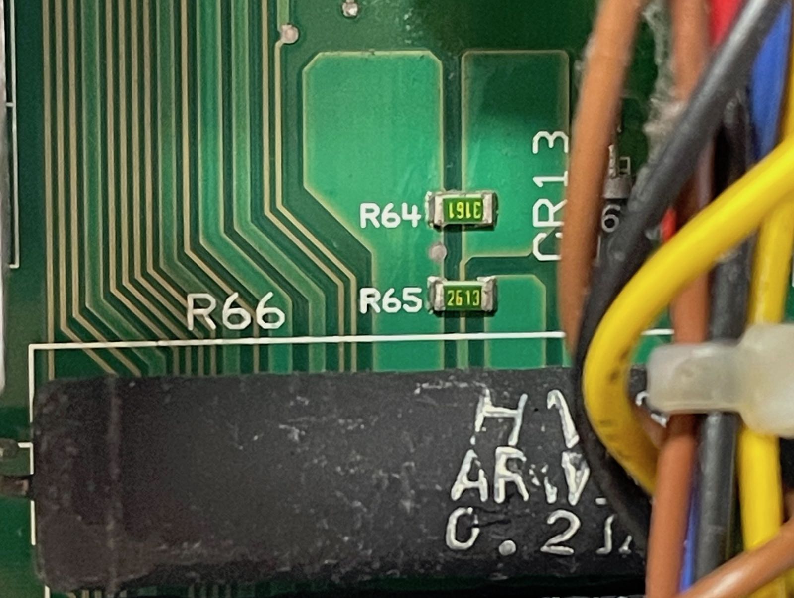
The results were as expected: the voltage measured on +25V_V_MON, the dot between the
R64 and R65 0.1% precision resistors, was exactly 1.12% of the output voltage. Perfectly in line with
what you get with a 3.15K/261K resistive divider.
BTW, R66 is the 10W 0.2 Ohm current measurement shunt.
The Solution
After the ADC, it’s all digital and firmware.
I ran the extended internal self-test (it only takes 2 seconds) which resulted in a PASS.
The only thing left to try was to recalibrate and see where that would get me. But remember the sticker: ‘Failed calibration tests’, ‘Equipment requires repair’, ‘Won’t Adjust’.
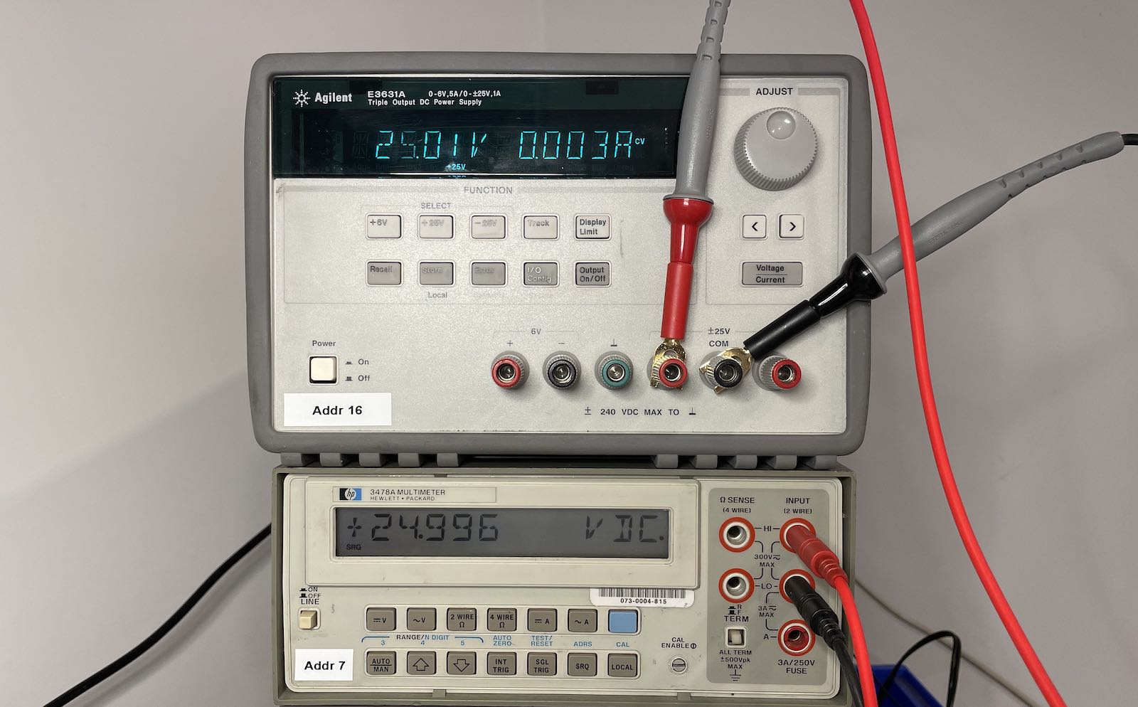
The E3631A calibration procedure is very modular: you can pick and choose what to calibrate and what not. I only went through +25V and -25V voltage calibration and nothing else. All it takes is an accurate multimeter and 2 minutes of your time.
After doing that, the E3631A worked as it should. DUH.
One way or the other, somebody must have miscalibrated the 25V and -25V outputs in the same way, and nobody thought about giving it another try…
Conclusion
You have no idea how many blog posts or Youtube videos there are about how a supposedly broken eBay purchase turned out to be just a matter of recalibrating the thing. I’ve read and watched quite a bit of them. And I ignored them.
Instead of an exhilarating repair adventure, I got served with a lesson to first check the obvious.
What a disappointment! :-)
But, seriously, I’m a working E3631A richer, and I learned a few new things about power supplies. I call that a win.
Not at bad way to spend an evening.