Repairing an HP 3478A Multimeter with a Hacksaw
- Introduction
- 3478A Features
- Documentation
- The 3478A Architecture
- A First Look inside the Box
- Tracking Down Failing Buttons
- Taking Everything Apart
- The Button Board to Main Board Connector
- Fix 1: Works, then Fails after 5 minutes
- Fix 2: Bring Out the Hacksaw!
- Conclusion
- References
Introduction
I’m slowly building a small stable of test and measurement equipment for my home lab. I’d be lying if I said that it’s out of hard necessity: almost all my projects are FPGA based and digital in nature. You don’t need a nice high precision power supply to power a generic FPGA development board, but when there’s one for offered on Craigslist for a good price, it’s hard to resist. One day that that GPIB control interface might come in real handy after all.
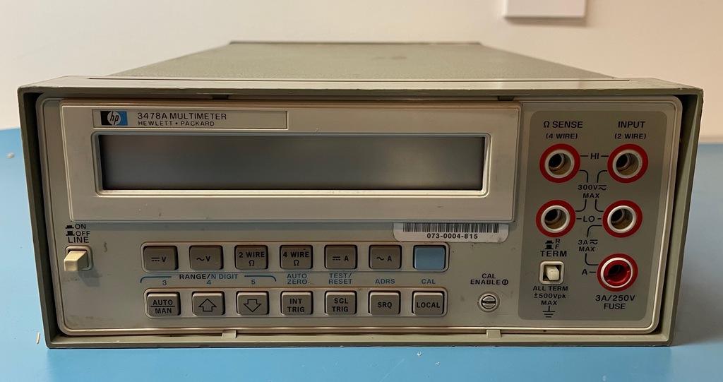
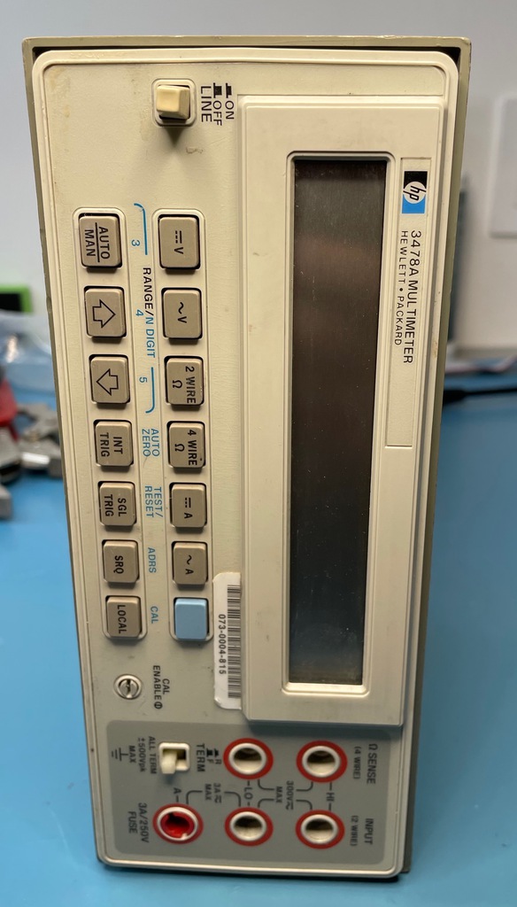
And that’s how, a few months ago, this HP 3478A benchtop multimeter appeared at my front door:
On eBay, these 5 1/2 digit meters go for around $140 when listed as Pre-Owned, while Parts Only devices go for around $70. In both cases, shipping cost is usually around $25. My unit was advertised as Pre-Owned with a “Passes Self-Test” description for a low low price of only $100, so I decided to take a chance on it.
Well, a passing self-test was what advertised, and a passing self-test is what I got!
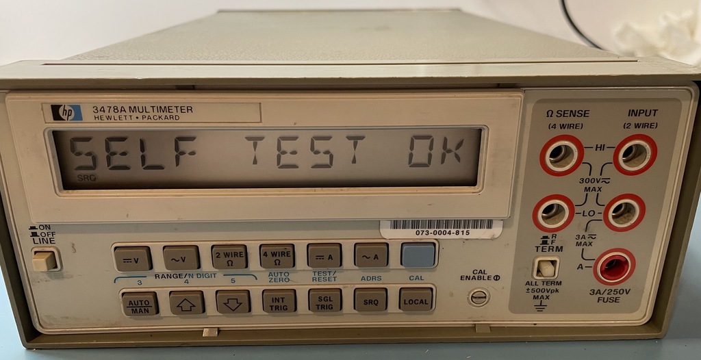
But that’s where it ended. Because other than the power switch, none of the front panel buttons had an effect. I could use the thing to measure DC voltages, the default setting after powering up, but that was about it.
The multimeter went onto an empty shelve, waiting for its time in the spotlight.
After playing with JTAG and other debugging techniques for a bit too long, Thanksgiving week was the perfect time to give the 3478A some tender loving care.
3478A Features
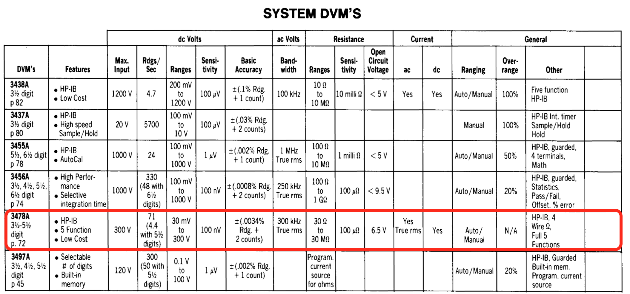
Check out the datasheet for the details, but here’s a quick summary of some of the 3478A features:
- 5 measurement types: AC and DC voltage, AC and DC current, resistance
- 3.5, 4.5 and 5.5 digit resolution
- 71 measurements per second when using 3.5 digit resolution
- GPIB interface
- 2-wire and 4-wire resistance measurement
- AC voltage and current measurements are true RMS
Let there be no doubt: a working 3478A far exceeds my measurement needs.
Documentation
The 3478A has been retired long ago, but there’s a lot of information online. It still has a page on the Keysight webiste, where it’s marked as obselete, but the operator’s and service manuals can found under the resources tab.
The service manual is great, with full schematics and detailed trouble-shooting instructions for all kinds of failure modes.
There’s also plenty of material of Youtube: teardowns, how to replace the calibration battery without losing calibration data (very important!), how to download and restore calibration data over GPIB, how to clean the display, and so forth.
There’s even a work-in-progress MAME 3478A emulator which is a great resource to understand some of the internals of the device.
This quote from discussion thread on the EEVblog forum is a bit ominous:
3478 are not bad but they are virtually unrepairable if they break. Especially the display is unobtainium…
But somebody managed to replace the LCD on a 3457A with an LED display so maybe something similar is possible on a 3478A?
Checkout the bottom of this blog post for a list.
The 3478A Architecture
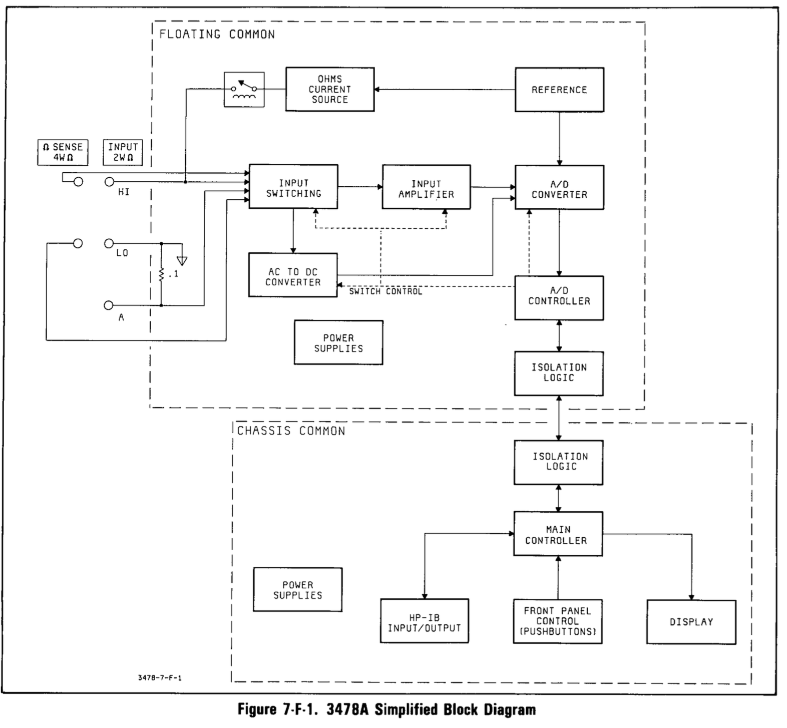
The 3478A first came to market in 1981. But despite being 40 years old, it has not one but 2 microcontrollers. That’s because it’s split into 2 electrically isolated sections: the “chassis common” section has the ground connected to the chassis and takes care of the display, the buttons, the GPIB interface, and configuration management. The “floating common” section handles measurements of voltage, current, and resistance.
The chassis common section has an Intel 8039 microcontroller without internal ROM. The ADC controller is an Intel 8049 with internal ROM. Both are microcontrollers of the Intel MCS-48 family with a whopping 128 bytes of on-chip RAM. The firmware of the 8039 is stored on an 8KB 2764 EPROM, one of those old style types that must be erased by shining a bright UV light on a glass window. A 256 x 4bit static RAM is used to store calibration data. A 3V lithium battery powers the SRAM when main power is switched off.
The AD converter of the 3478A doesn’t use a high precision integrated circuit, but it’s built from discrete components and uses an integrator, a voltage reference and a comparator, under control of the 8049 microcontroller.
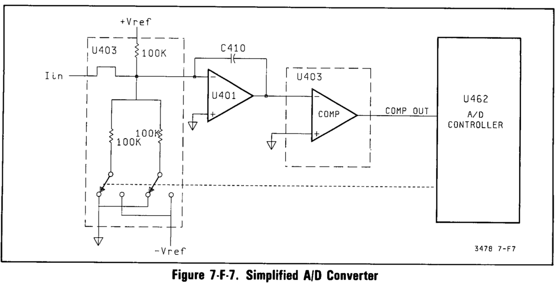
The ADC is based on a dual-slope conversion:
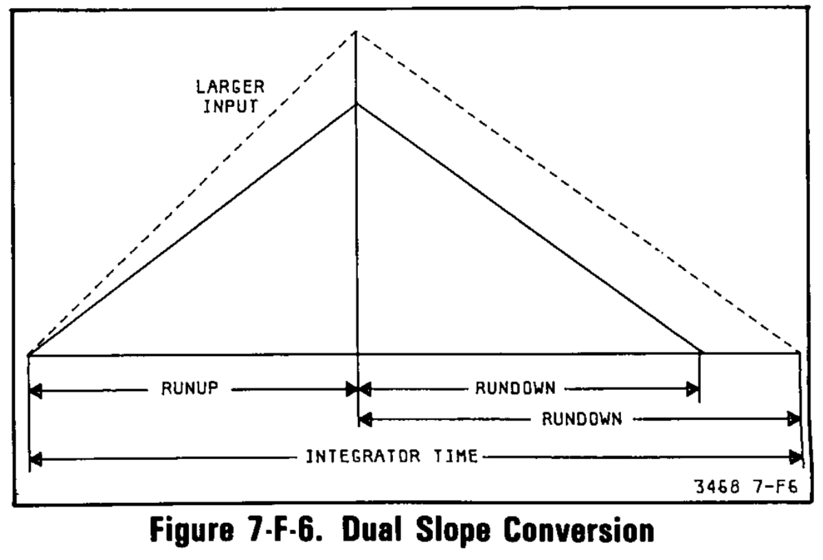
- During the runup phase, the signal that must be measured is applied to the input of the integrator for a fixed amount of time.
- This charges a capacitor with a charge that’s proportional to the voltage of the signal.
- during the following rundown phase, the integrator is discharged by applying a constant, known voltage reference to the input.
- the time needed to discharge the capacitor is proportional to the voltage of the input signal.
In other words, the AD convertor transforms a voltage to time, which is much easier to measure with high precision.
The real implementation is a bit more complex and uses the so-called Multi-Slope II method, which uses the runup phase to determine the most significant digits and the rundown phase for the least significant digits.
The detailed explanation is well beyond the scope of this blog post, but section 7-F-31 of the service manual describes the process very well.
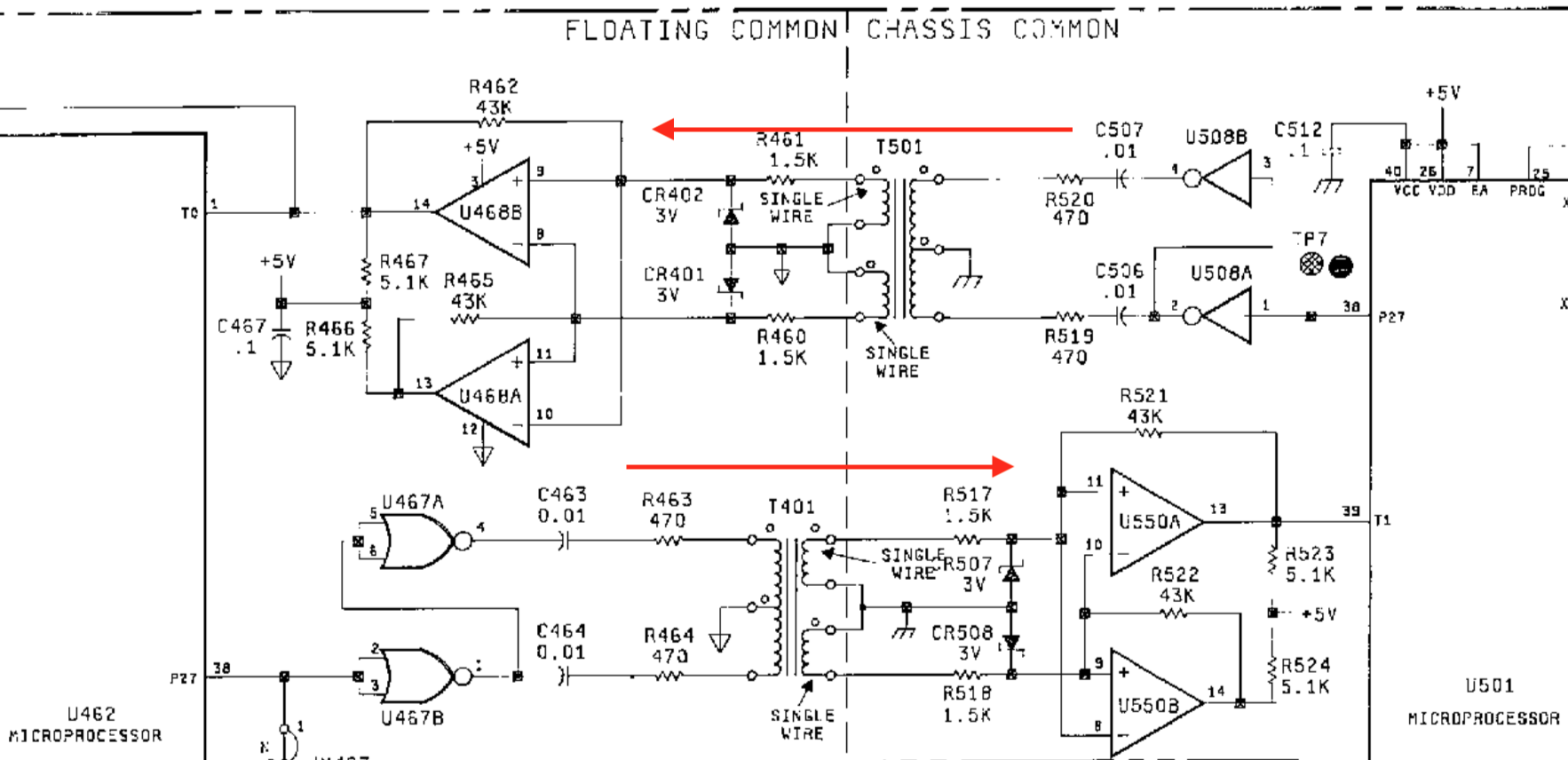
The floating ground of the measurement section makes it possible to connect the ground of the multimeter to any random reference point of the device under test and measure other voltage compared to that reference point. However, since the digital control section and the measurement section must remain electrically isolated, communication between the section can’t be done with a simple wire.
In most such configurations, an optocoupler is used. Later versions of the 3478A, such as the one featured in the EEVblog teardown video, use exactly that. But older ones like mine have magnetic couplers. There’s one for each direction, from the digital part to the measurement part, and back.
A First Look inside the Box
To get a first inside look, you need to remove 2 screws on the back, and one in the back at the bottom. The metal enclosure will slide right off, and you get to see this:
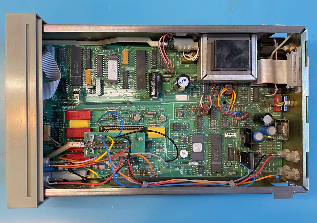
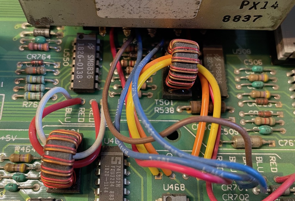
The layout is really straigthforward. You can clearly see the separation between the control and power sections at the top and the floating measurement section at the bottom. And just below the main power transformer on the right, there’s the 2 smaller transformers that form the magnetic couplers.
Tracking Down Failing Buttons
Time to starting looking at the issue at hand: failing buttons. Not one, not a few, but all of them. That can be a good thing, because it suggest that’s there’s a single, catastrophic, issue. Chances are that fixing this one thing will make all buttons work again.
The schematic couldn’t be easier:
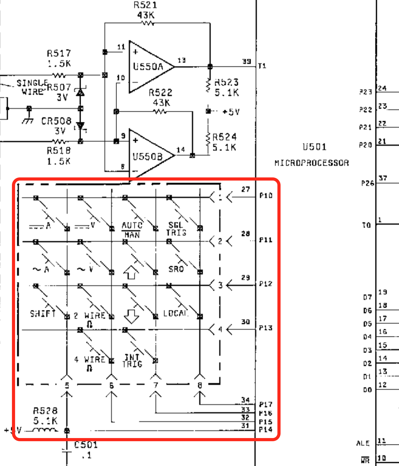
The expected 14 buttons are wired up in a 4 by 4 matrix configuration that is controlled by 8 GPIO pins of digital control microcontroller U501.
With a circuit this simple, there’s only a few possible ways things could fail:
-
the switches of the buttons are broken.
But what are the chances that all buttons are broken at the same time?
-
the ports P10-P17 of the microcontroller are broken.
In other words, the microcontroller is toast. That’d be a worst case situation.
-
a connection issue between the microcontroller and the buttons.
Since the device is still printing out “Self Test OK” and showing a DC voltages, the microcontroller is at least partially working, so the last option is the most likely.
I first put a continuity tester on the ~A button, pressed it and had a beep. (Good!) Then I put the probes on pins 28 and 31 (ports P11 and P14) of the microcontroller, pressed the button again, and… got nothing.
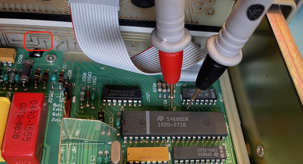
Conclusion: it’s almost certainly a connection issue between button board PCB and the main PCB!
Let’s have a closer look at this connector.
Taking Everything Apart
It’s easier said than done: the connector is on the bottom side of the PCB and impossible to reach because there’s a fat bezel around it. We’ll have to take the thing apart. Or at least partially: the main PCB, and the front assembly with the buttons and the LCD needs to slide out enough to get access to the button PCB and the connector that links it to the main PCB.
The disassembly isn’t very complicated, but make sure to keep track of how cables were connected so that you can later reconnect them correctly. (Or just use the pictures below!)
Here’s a short list of what I needed to do:
-
Unplug the GPIB cable. This took quite a bit of effort, and was probably the scariest part.
One pin of the connector was bent. I’m almost certain that it was already bent before I removed it.
-
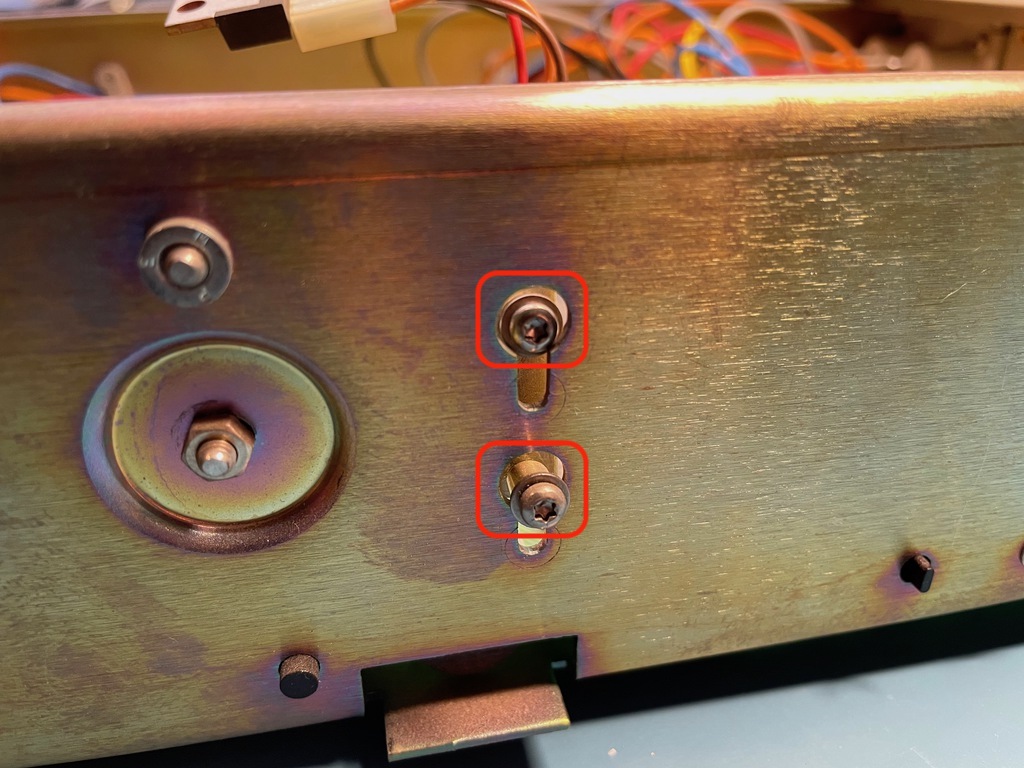
Loosen the main power switch assembly by removing its 2 screws.
-
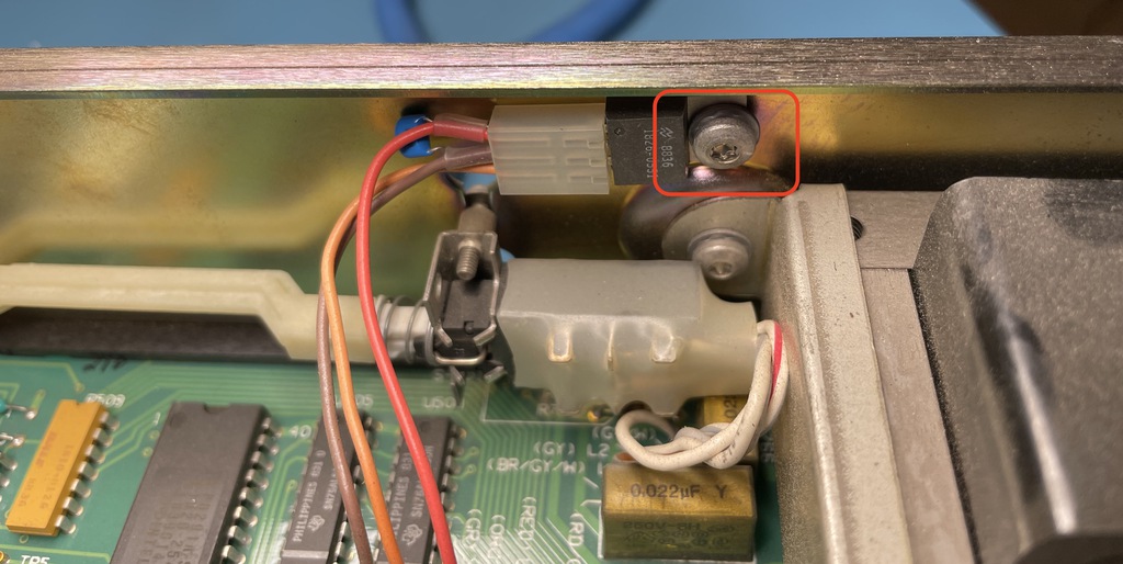
Dismount the power regulator that’s screwed to the chassis right next to the power switch.
-
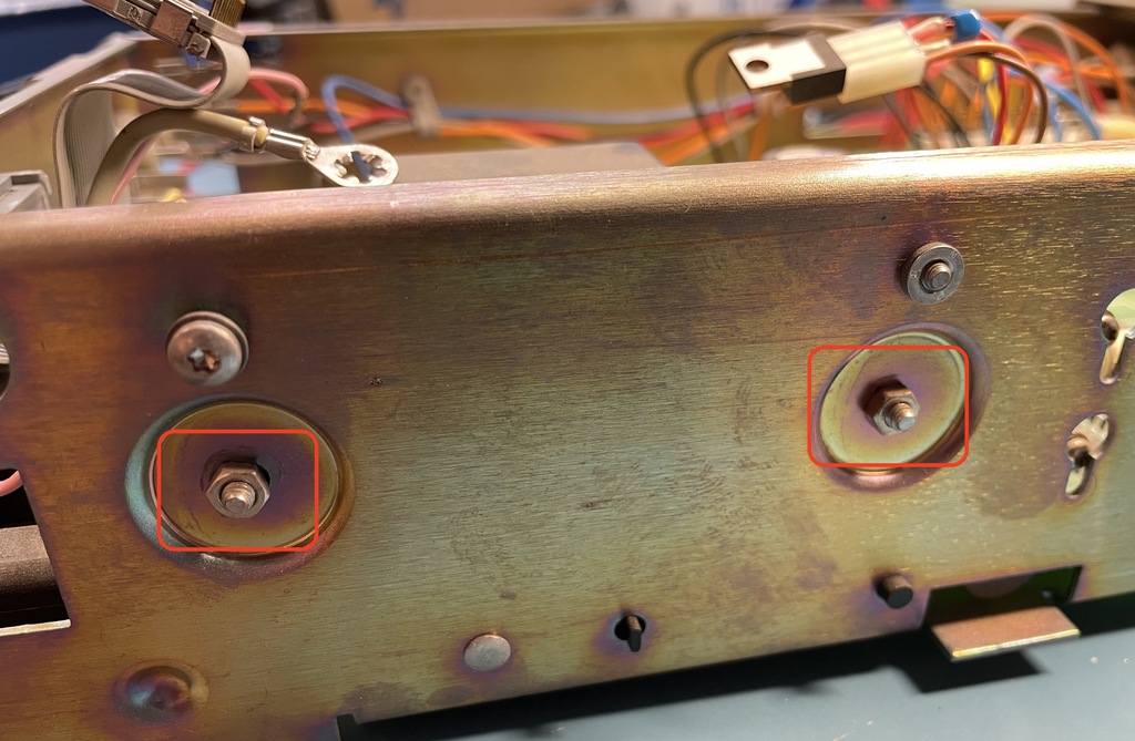
Remove the 2 screws that tie the main transformer to the chassis.
-
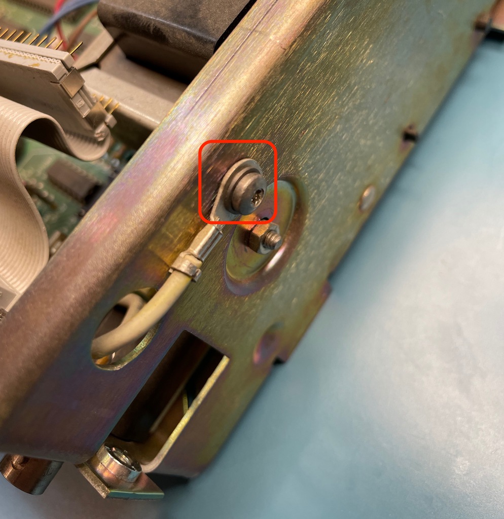
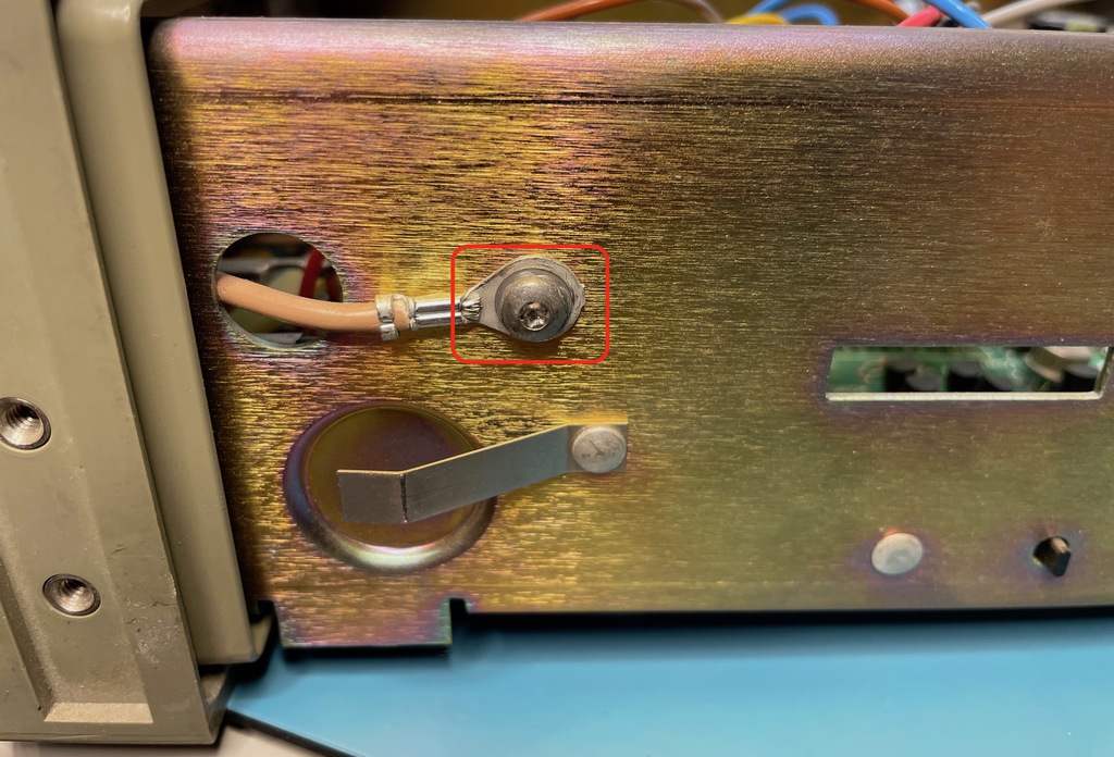
Remove the ground chassis screw in the back.
-
Remove the ground chassis screw in the front.
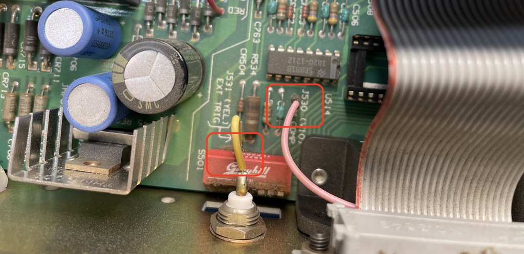
-
Unplug the yellow and pink wires next to the GPIB plug.
-
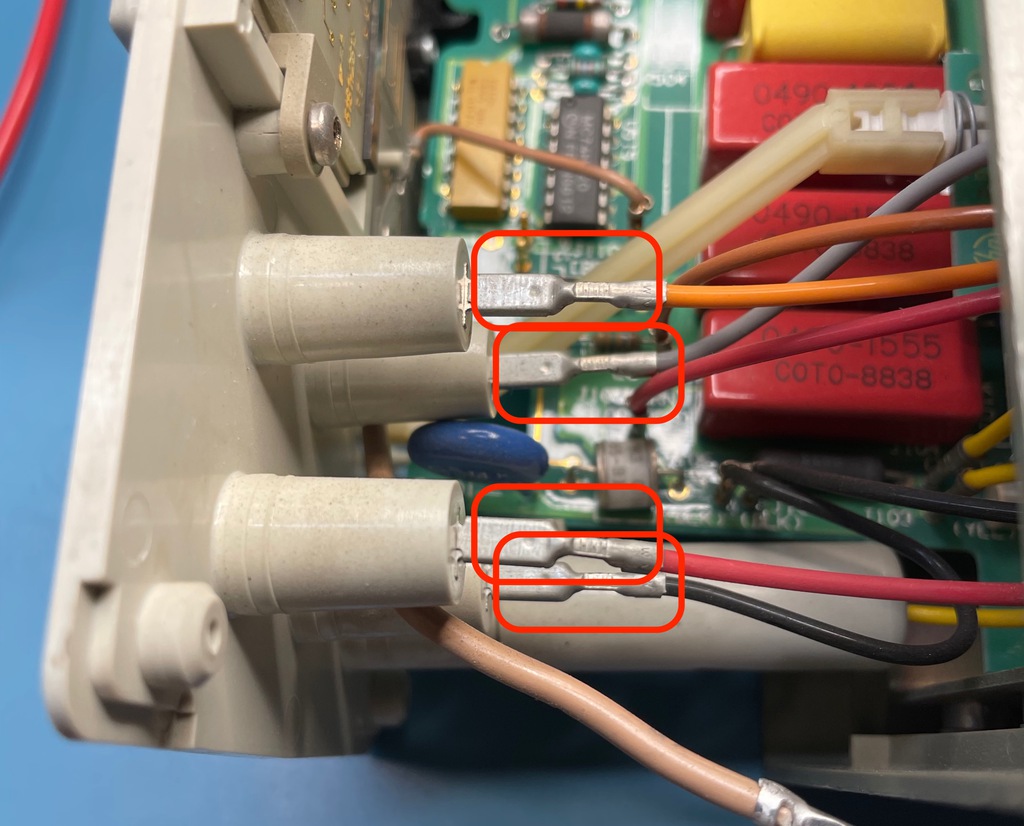
Unplug the orange, brown, read, black and blue wires in the back.
-
Rotate the device 90 degrees so that it rests on a narrow side, with the front facing to you. You’ll see 4 notches that keep the PCBs locked into place.
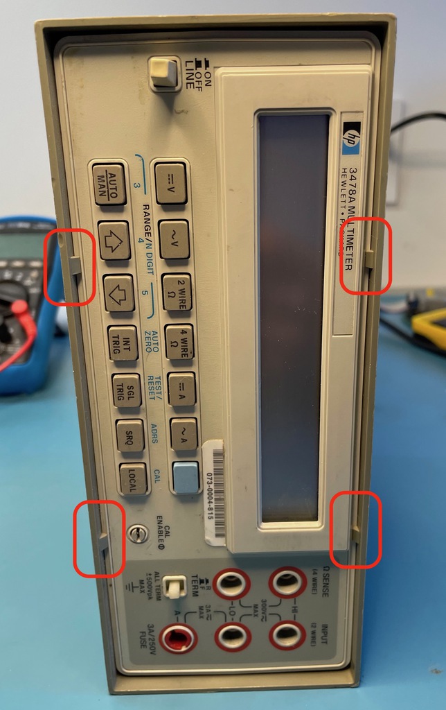
-
Force the plastic enclosure open to unlock the front panel, and apply some pressure on the power connector in the back. When all 4 notches are unlock, the front panel and main PCB will slide forward.
Don’t slide out everything out completely: the 5 wires that you unplugged earlier are connected to the chassis through some ties. It’s sufficient to slide everything forward by a little bit over an inch or 2.
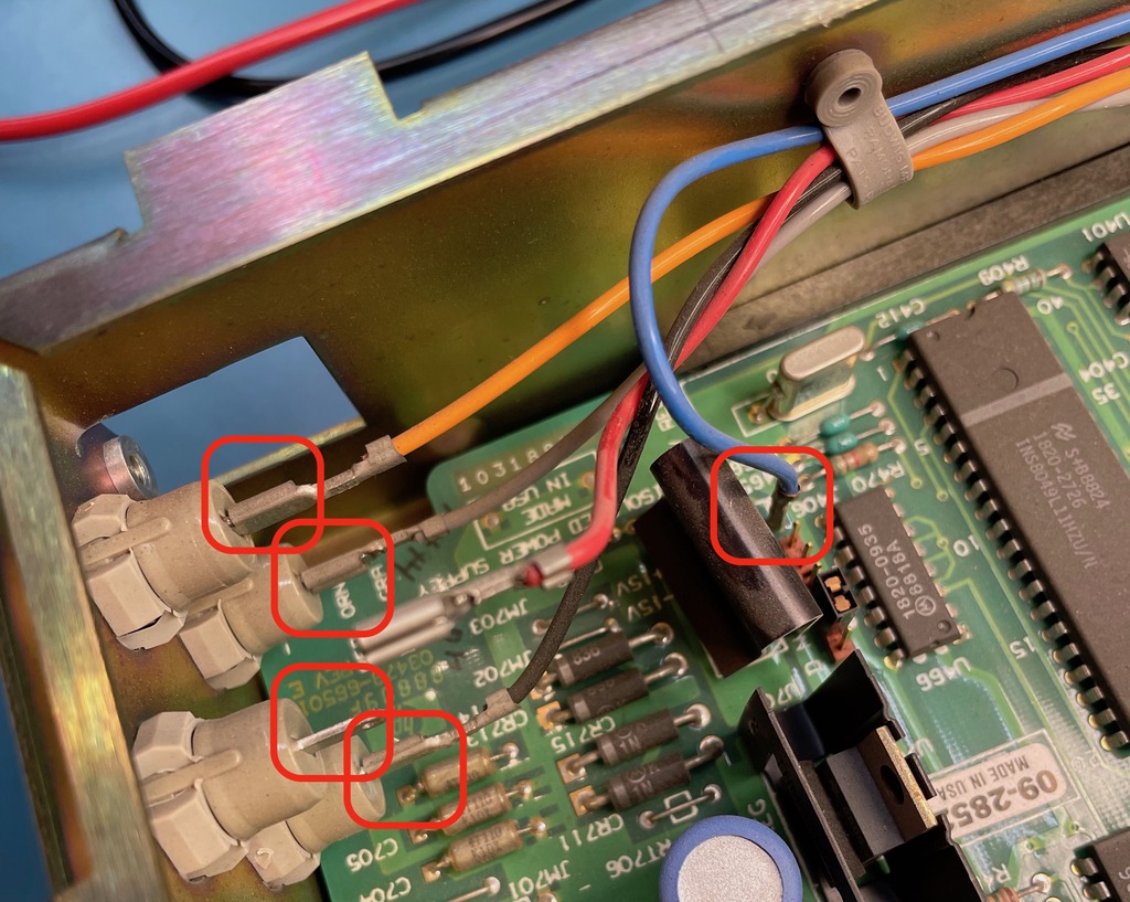
-
Unplug 4 wires between the front panel and the main board: orange, gray, red, black.
-
Finally, unplug the yellow wire, also between the front panel and the main board, but this time, the fixed pin is located on the main board, and a bit recessed below the plastic enclosure.
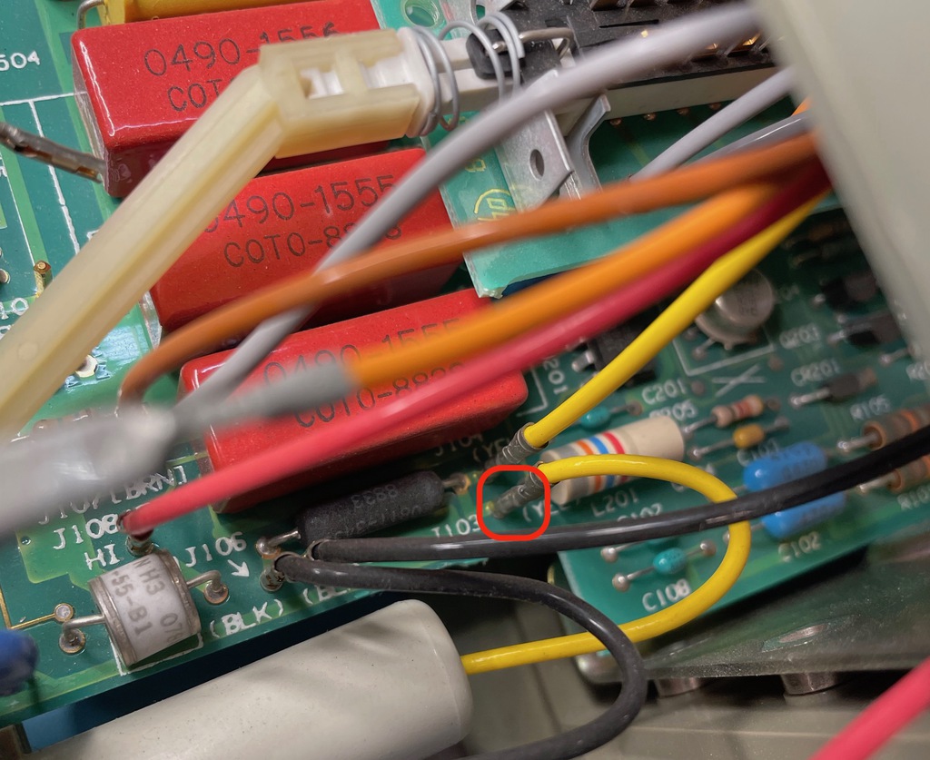
-
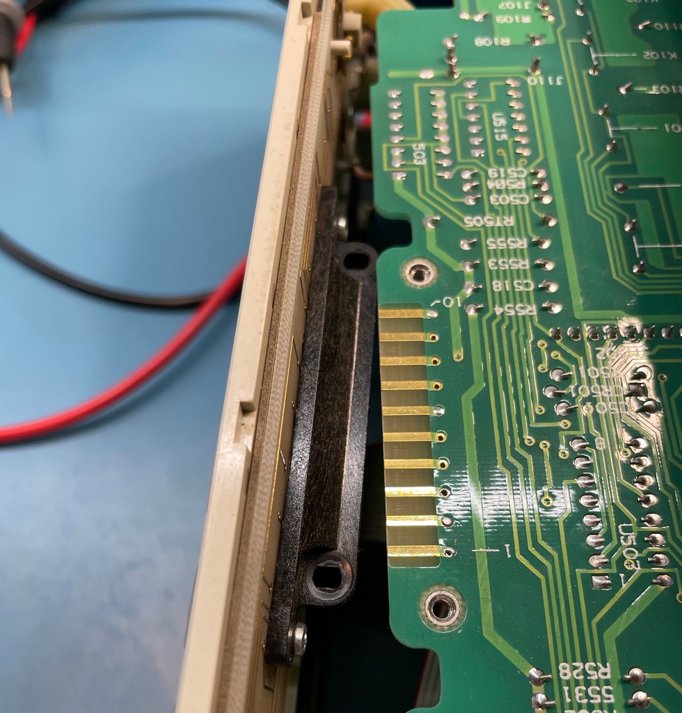
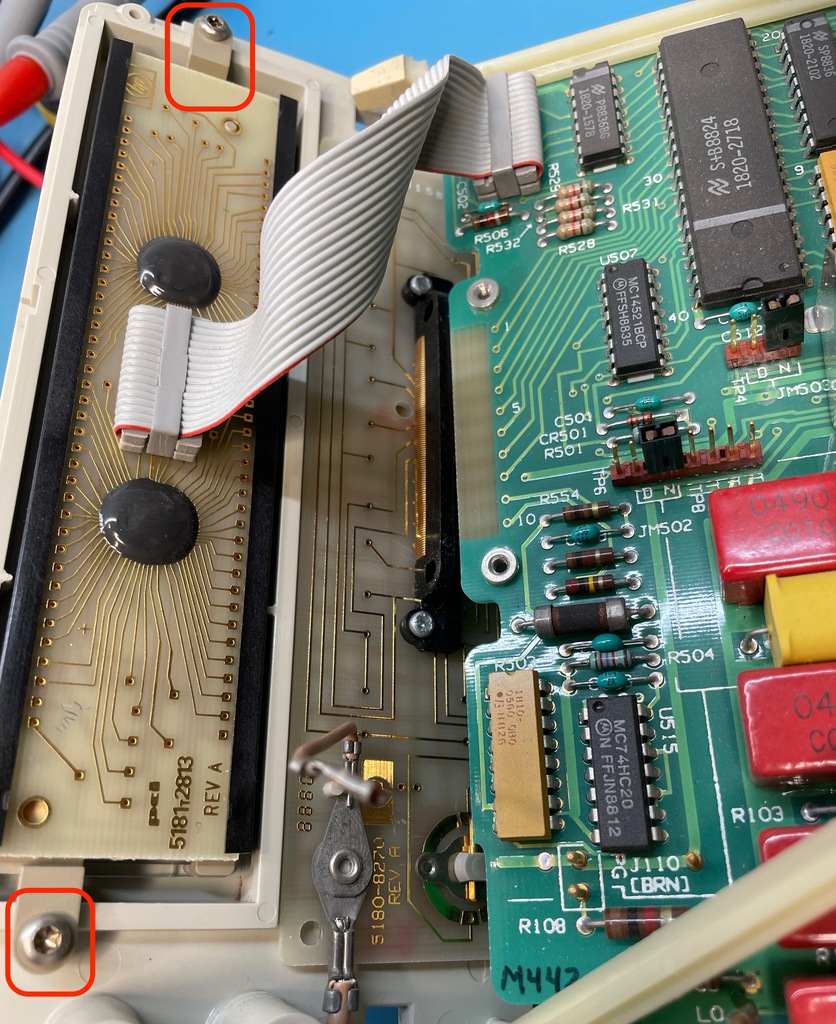
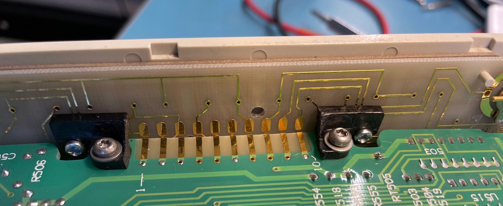
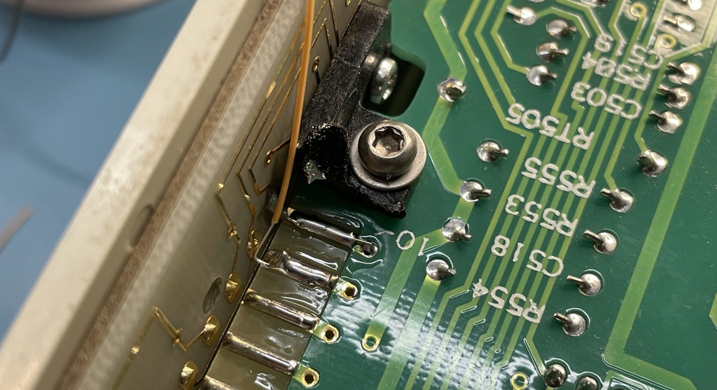
Turn the device upside down. You can see the connector between the button PCB and the main board:
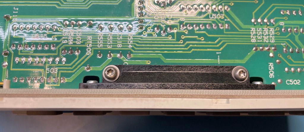
-
Remove those 2 screws. The front panel will now be loose, except for the flat-cable that goes between the main board and the LCD.
-
If it’s possible to unplug the cable between LCD and main board, it’s definitely hard to do so. Much easier to keep it connected and unscrew the LCD from the front panel instead.
-
The front panel is now completely disconnected. Let’s remove those last 2 screws to remove the connector from the front panel.
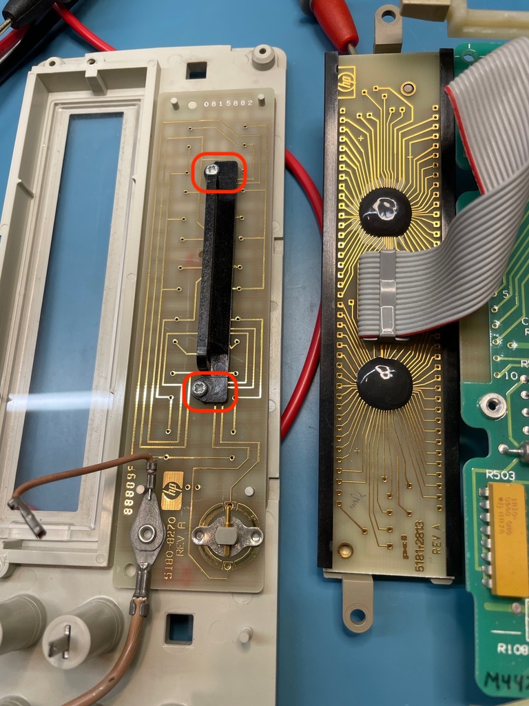
-
With the connector removed, we are at the end of this journey!
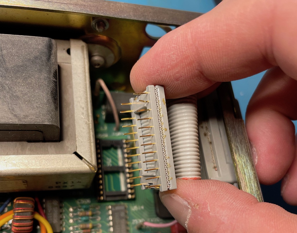
The Button Board to Main Board Connector
The electrical connection between the 2 button board and the main board is unusual: instead of a cable, there is a element with a 90 degree angle that consists of tiny individual metal wires. The connector presses this element against the copper pads on both PCBs and creates an electric connection between them.
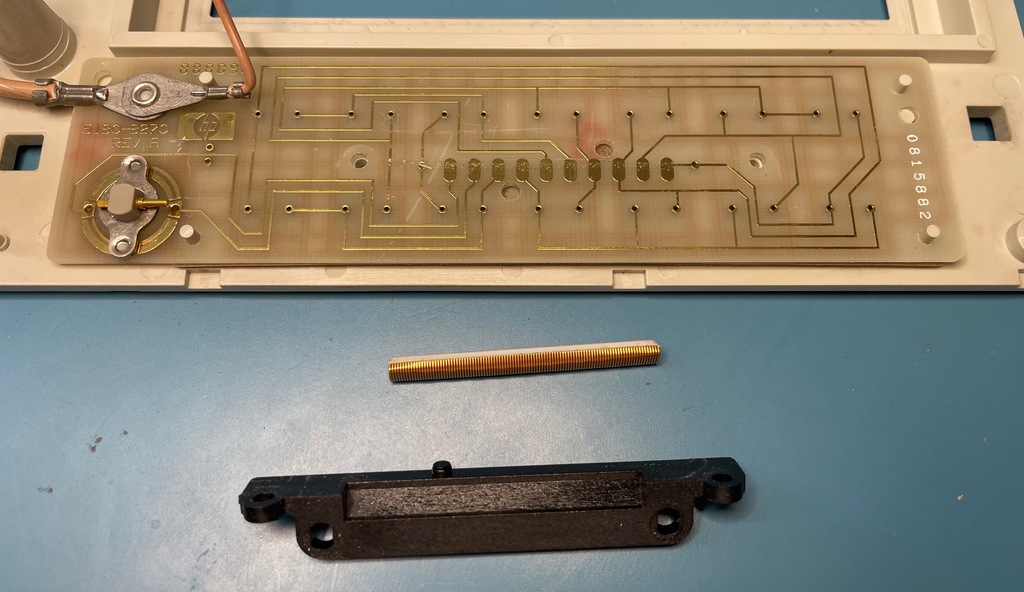
Or at least, that’s what it’s supposed to do.
One way or the other, all 8 connections on my device stopped working. I assume it had to do with oxidation on the contacts?
This method of linking 2 board seems flimsy to me, and prone to fail over time. On the other hand, Google didn’t find anything related to buttons failing on 3478A multimeters, so maybe mine is really an exception?
Fix 1: Works, then Fails after 5 minutes
Everything looked very clean, no visible oxidation to be seen, but I used isopropyl alcohol to clean the contacts and connection strip. I assembled the connector back onto the LCD and the main board PCB and verified with a continuity tester that there was an electrical connection now between all contacts.
I then put the whole multimeter back together (retrace all the steps I documented earlier), powered it on and… SUCCESS!
All buttons were now working perfectly… for 5 minutes.
After that, 4 out of the 14 buttons became unresponsive again.
Fix 2: Bring Out the Hacksaw!
If that unusual connector mechanism doesn’t work, why not switch to the more traditional way of doing things, with wires? That’s exactly what I did.
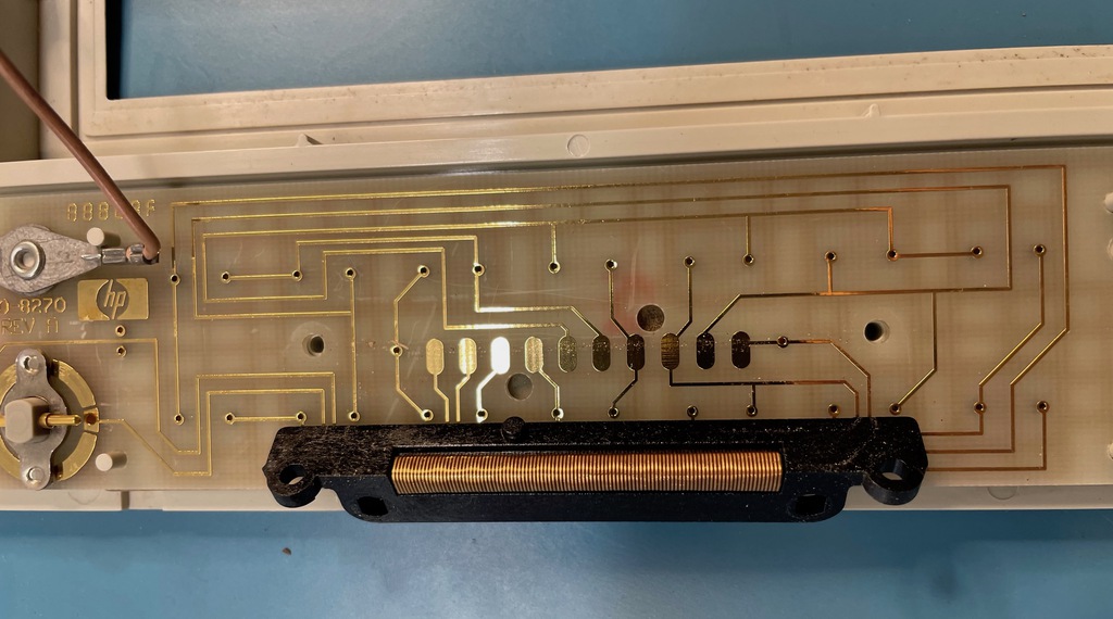
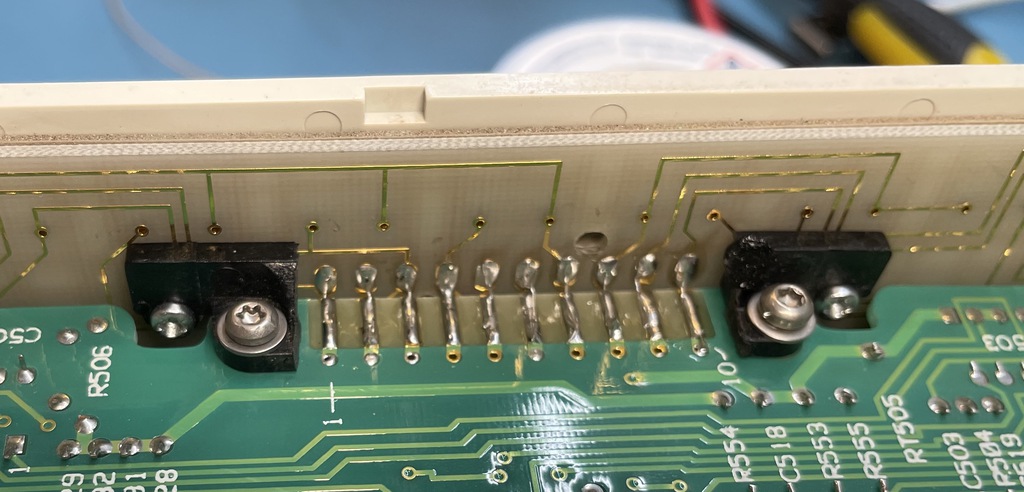
The connector is still useful to mechanically align the 2 PCBs, so I simply sawed away the center part of the connector, retained the 2 ends with the screw holes, and ended up with this:
The rest is obvious: I soldered a tiny wire between each of the connection pads.
Instead of using a tiny wire, I could have created a solder bridge between the opposing connection pads of the 2 PCBs, but that would probably have been too brittle to survive long term use. A wire will allow some flex when enthousiastically pressing on a button.
After soldering all connections, it looked like this:
I went through the whole reassembly procedure once more, and, again… SUCCESS! But this time, it kept working after 5 minutes.
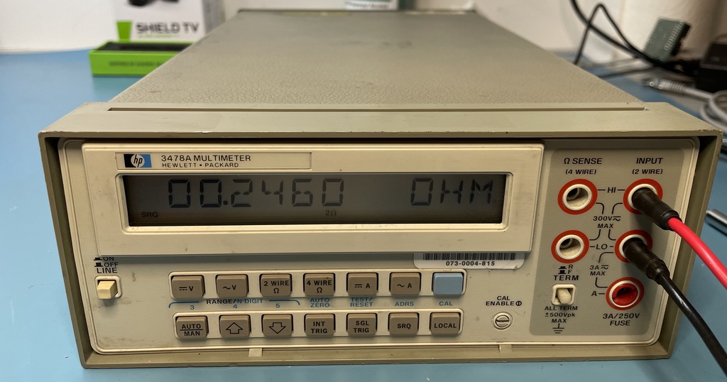
Here’s the multimeter measuring a zero Ohm connection with some very cheap crocodile clips.
Conclusion
This was a fun evening project, and I’ve learned a bunch about the internal of multimeters too. There’s a lot of information out there. I’ve listed some of it in the references below.
I’ve compared a number of measurements between my handheld multimeter and this one, and the results are pretty much the same. That said, I have no clue how long it has been since the meter was last calibrated, and I don’t have any calibrated voltage sources or reference resistors so who knows how accurate my measurements really are? Since calibration can easily cost $100 or more, I have no plans to do so until I really need 5 digit accuracy.
For now, the multimeter will take its place back on the shelve. A handheld multimeter is more convenient. But if, one day, I’ll need an automated measurement setup, it will be ready to go.
After publishing this blog post, multiple people told me to replace the RIFA capacitors and to replace up the permanent battery. It took more than year before I got to that, but I write about that in HP 3478A Multimeter Calibration Data Backup and Battery Replacement.
References
Official Documentation
- 3478A Datasheet
- 3478A Service Manual
-
Technical description of the closely related 3468A multimeter.
- HP Catalog 1983
- Keysight 3478A
Youtube Videos
- EEVblog #427 - HP 3478A Multimeter Teardown
- NFM - HP 3478A Multimeter Repair and Test
- Tony Albus - HP 3478A Multimeter Teardown
Various Discussions and Articles