A Hardware Interposer to Fix the Symmetricom SyncServer S200 GPS Week Number Rollover Problem
- Introduction
- IMPORTANT: Use the Right GPS Antenna!
- The Problem: SyncServer Refuses to Lock to GPS
- The GPS Week Number Rollover Issue
- Making the Furuno GT-8031 Work Again
- How It Works
- Build Instructions
- Power Supply Recapping
- The Future: A Software-Only Solution
- The Result
- References
- Footnotes
Introduction
In my earlier blog post, I wrote about how to set up a SyncServer S200 as a regular NTP server, and how to install the backside BNC connectors to bring out the 10 MHz and 1PPS outputs.
The ultimate goal is to use the SyncServer as a lab timing reference, but at the end of that blog post, it’s clear that using NTP alone is not good enough to get a precise 10 MHz clock: the output frequency was off by almost 100Hz!
To get a more accurate output clock, you need to synchronize the SyncServer to the GPS system so that it becomes a GPS disciplined oscillator (GPSDO) and a stratum 1 time keeping device.
The S200 has a GPS antenna input and a GPS receiver module inside, so in theory this should be a matter of connecting the right GPS antenna. But in practice it wasn’t simple at all because the GPS module in the SyncServer S200 is so old that it suffers from the so-called Week Number Roll-Over (WNRO) problem.
In this blog post, I’ll discuss what the WNRO problem is all about and show my custom hardware solution that fixed the problem.
IMPORTANT: Use the Right GPS Antenna!
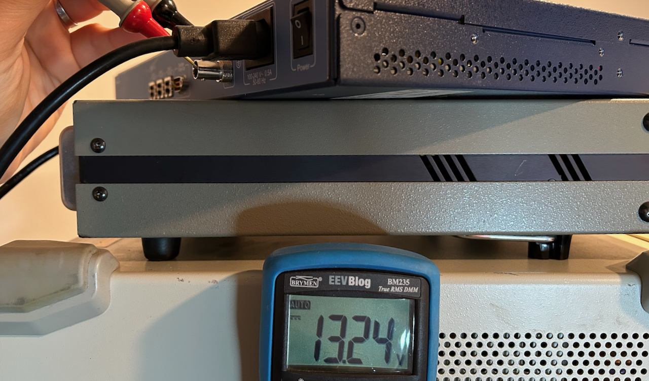
Let me once again point out the importance of using the right GPS antenna to avoid damaging it permanently due to over-voltage.
GPS antennas have active elements that amplify the received signal right at the point of reception before sending it down the cable to the GPS unit. Most antennas need 3.3V or 5V that is supplied through the GPS antenna connector, but Symmetricom S200 supplies 12V!
Make sure you are using a 12V GPS antenna!
Check out my earlier blog post for more information.
The Problem: SyncServer Refuses to Lock to GPS
When you connect a GPS antenna to a SyncServer in its original configuration, everything seems to go fine initially. The front panel reports the antenna connection as “Good”, a few minutes later the number of satellites detected goes up, and the right location gets reported.
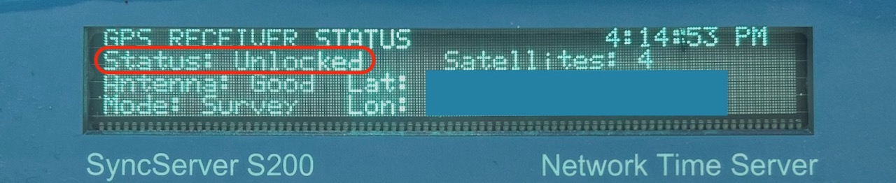
But the most important “Status” field remains stuck in the “Unlocked” state which means that the SyncServer refuses to lock its internal clock to the GPS unit.
This issue has been discussed to death in a number of EEVblog forum threads, but conclusion is always the same: the Furuno GT-8031 GPS module suffers from the GPS Week Number Roll-Over (WNRO) issue and nothing can be done about it other than replacing the GPS module with an after-market replacement one.
The GPS Week Number Rollover Issue
The original GPS system used a 10-bit number to count the number of weeks that have elapsed since January 6, 1980. Every 19.7 years, this number rolls over from 1023 back to 0. The first rollover happened on August 21, 1999, the second on April 6, 2019, and the next one will be on November 20, 2038. Check out this US Naval Observatory presention for some more information.
GPS module manufacturers have dealt with the issue is by using a dynamic base year or variable pivot year. Let’s say that a device is designed in at the start of 2013 during week 697 of the 19.7 year epoch that started in 1999. The device then assumes that all week numbers higher than 697 are for years 2013 to 2019, and that numbers from 0 to 697 are for the years 2019 and later.
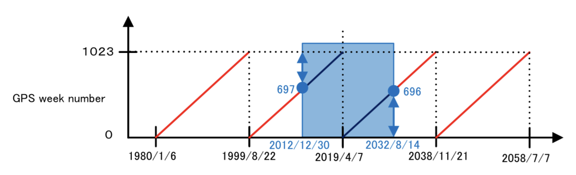
Such a device will work fine for the 19.7 years from 2013 until 2032.
And with just a few bits of non-volatile storage it is even possible to make a GPS unit robust against this kind of rollover forever: if the last seen date by the GPS unit was 2019 and suddenly it sees a date of 1999, it can infer that there was a rollover and record in the storage that the next GPS epoch has started. Unfortunately many modules don’t do that. The only way to fix the issue is to either update the module firmware or for some external device to tell the GPS module about the current GPS epoch.
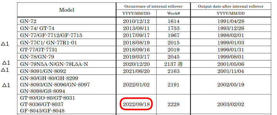
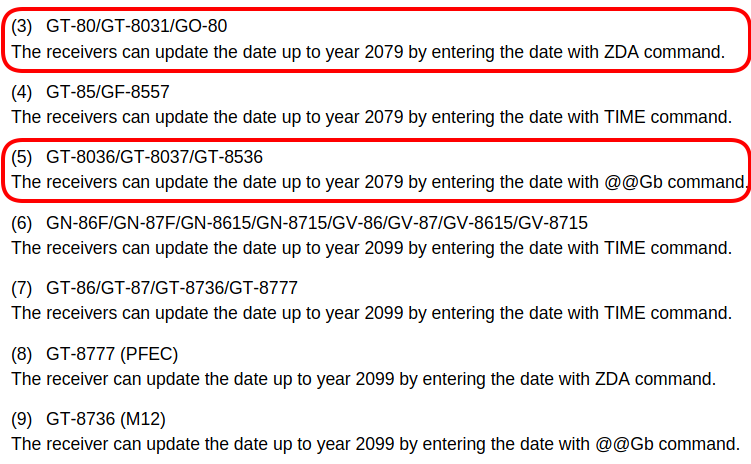
Many SyncServer S2xx devices shipped with a Motorola M12 compatible module that is based on a Furuno GT-8031 which has a starting date of February 2, 2003 and rolled over on September 18, 2022. You can send a command to the module that hints the current date and that fixes the issue, but there is no SyncServer S200 firmware that supports that. Check out this Furuno technical document for more the rollover details.
The same document also tells us how to adjust the rollover date. It depends on the protocol
that is supposed by the module. For a GT-8031, you need to use the ZDA command, other modules require the
@@Gb or the TIME command.
If you want to run a SyncServer for its intended purpose, a time server, it is of course important that you get the correct date. But if you don’t care about the date because the primary purpose it to use it as a GPSDO then the 1PPS output from the GPS module should be sufficient to drive a PLL that locks the internal 10 MHz oscillator to the GPS system.
This 1PPS signal is still present on the GT-8031 of my unit and I verified with an oscilloscope that it matches the 1PPS output of my TM4313 GPSDO both in frequency and in phase as soon as it sees a copule of satellites.
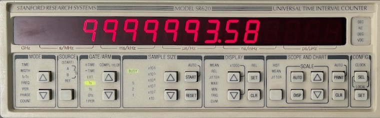
But there is something in the SyncServer firmware that depends on more than just the 1PPS signal because my S200 refuses to enter into “GPS Locked” mode, and the 10 MHz oscillator stays in free-running mode at the miserable frequency of roughly 9,999,993 Hz.
Making the Furuno GT-8031 Work Again
There are aftermarket replacement modules out there with a rollover date that is far into the future, but they are priced pretty high. There’s the iLotus IL-GPS-0030-B Module which goes for around $100 in AliExpress but that one has a rollover date on August 2024, and other modules go as high as $240. The reason for these high prices is because these modules don’t use a $5 location GPS chip but specialized ones that are designed for accurate time keeping such as the u-blox NEO/LEA series.
Instead of solving the problem with money, I wondered if it was possible to make the GT-8031 send the right date to the S200 with a hardware interposer that sits between the module and motherboard. There were 2 options:
-
intercept the date sent from the GPS module, correct it, and transmit it to the motherboard
I tried that, but didn’t get it work.
-
send a configuration command to the GPS module to set the right date
This method was suggested by Alex Forencich on the time-nuts mailing list. He implemented it by patching the firmware of a microcontroller on his SyncServer S350. His solution might be the best one eventually, it doesn’t require extra hardware, but by the time he posted his message, my interposer was already up and running on my desk.
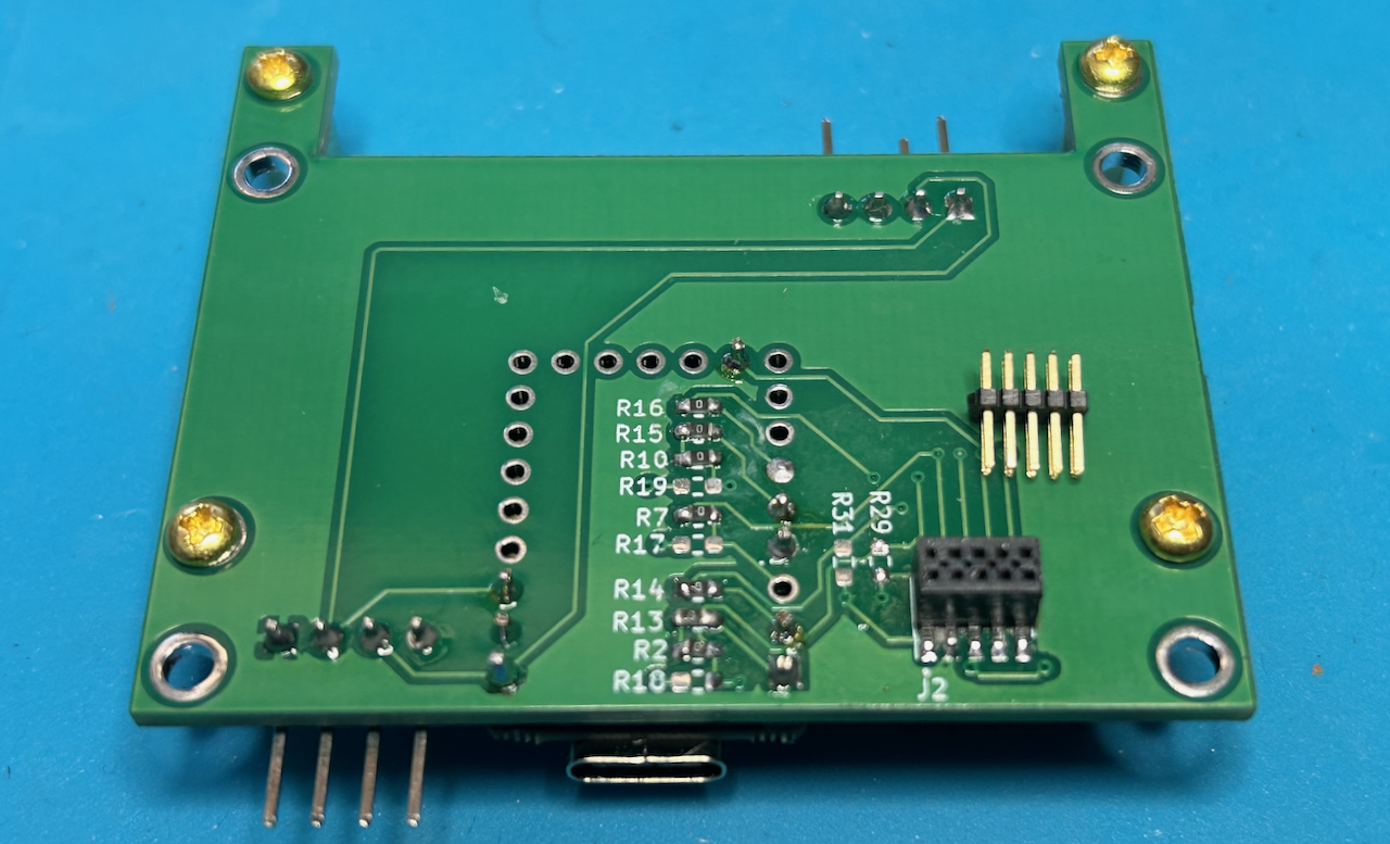
It took 2 PCB spins, but I eventually came up with the following solution:
 Click to enlarge
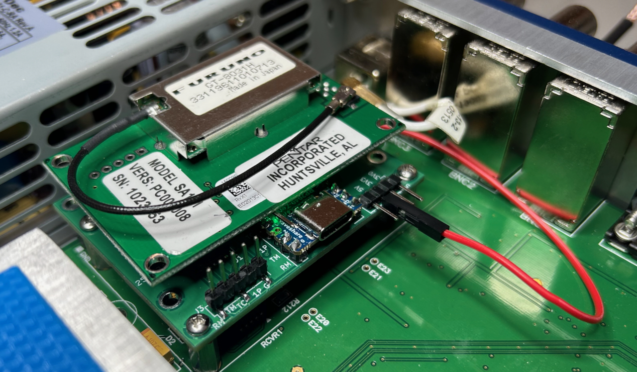
In the picture above, you see the GT-8031 plugged into my interposer that is in turn plugged into the motherboard.
The interposer itself looks like this:
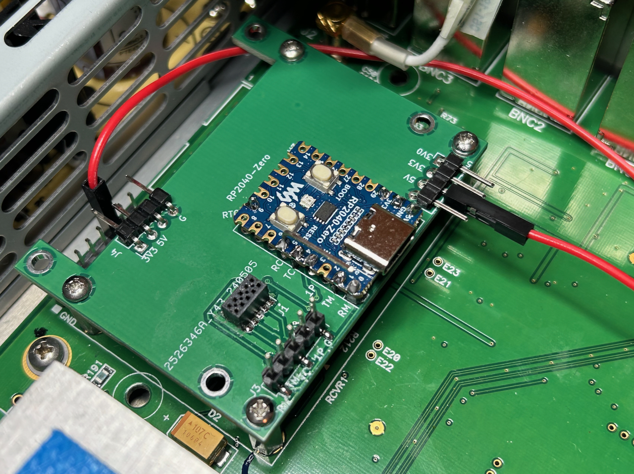
The design is straightforward: an RP2024-zero, a smaller variant of the Raspberry Pico, puts itself in between the serial TX and RX wires that normally go between the module and the motherboard. It’s up to the software that runs on the RP2040 to determine what to do with the data streams that run over those wires.

There are a few of other connectors: the one at the bottom right is for observing the signals with a logic analyzer. There are also 2 connectors for power. When finally installed, the interposer gets powered with a 5V supply that’s available on a pin that is conveniently located right behind the GPS module. In the picture above, the red wires provides the 5V, the ground is connected through the screws that hold the board in place.
The total cost of the board is as follows:
- PCB: $2 for 5 PCBs + $1.50 shipping = $3.50
- RP2040-zero: $9 on Amazon
- 2 5x2 connectors: $5 on Mouser + $5 shipping = $10
Total: $22.50
The full project details can be found my gps_interposer GitHub repo.
How It Works
To arrive at a working solution, I recorded all the transactions on the serial port RX and TX and ran them through a decoder script to convert them into readable GPS messages.
Here are the messages that are exchanged between the motherboard after powering up the unit:
>>> @@Cf - set to defaults command: [], [37], [13, 10] - 7
>>> @@Gf - time raim alarm message: [0, 10], [43], [13, 10] - 9
>>> @@Aw - time correction select: [1], [55], [13, 10] - 8
>>> @@Bp - request utc/ionospheric data: [0], [50], [13, 10] - 8
>>> @@Ge - time raim select message: [1], [35], [13, 10] - 8
>>> @@Gd - position control message: [3], [32], [13, 10] - 8
<<< @@Aw - time correction select: [1], [55], [13, 10] - 8
    time_mode:UTC
<<< @@Co - utc/ionospheric data input: [0, 0, 0, 0, 0, 0, 0, 0, 0, 0, 0, 0, 0, 0, 0, 0, 0, 0, 0, 0, 0, 0], [44], [13, 10] - 29
    alpha0:0, alpha1:0, alhpa2:0, alpha3:0
    beta0:0, beta1:0, alhpa2:0, beta3:0
    A0:0, A1:0
    delta_tls:0, tot:0, WNt:0, WNlsf:0, DN:0, delta_Tlsf:0
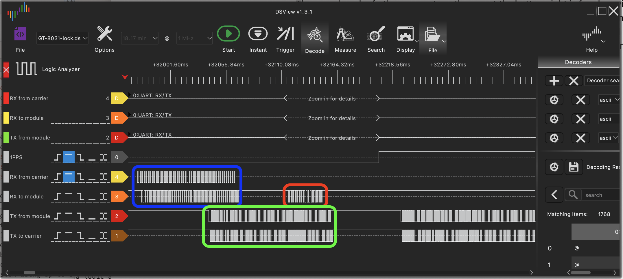
The messages above can be seen in the blue and green rectangles of this logic analyzer screenshot:
 Click to enlarge
Earlier, we saw that the GT-8031 module itself needs the ZDA command to set the time. This is an
NMEA command. The messages above are Motorola M12 commands however.
On the M12 module that contains the GT-8031 there is also a TI M430F147
microcontroller that takes care of the conversion between Motorola and NMEA commands.
Note how the messages that arrive at the interposer immediately get forwarded to the other side. But there is
one transaction marked in red, generated by the interposer itself, that sends the @@Gb command. When the GPS module
is not yet locked to a satelllite, this command sends an initial estimate of the current date and time. The
M12 User Guide has the following to say about this command:
The interposer sends a hinted date of May 4, 2024. When the GPS module receives date from its first satellite, it corrects the date and time to the right value but it uses the initial estimated date to correct for the week number rollover!
I initially placed the @@Gb command right after the @@Cf command that resets the module to default values, but that didn’t work. The solution was to send it after the initial burst of configuration commmands.
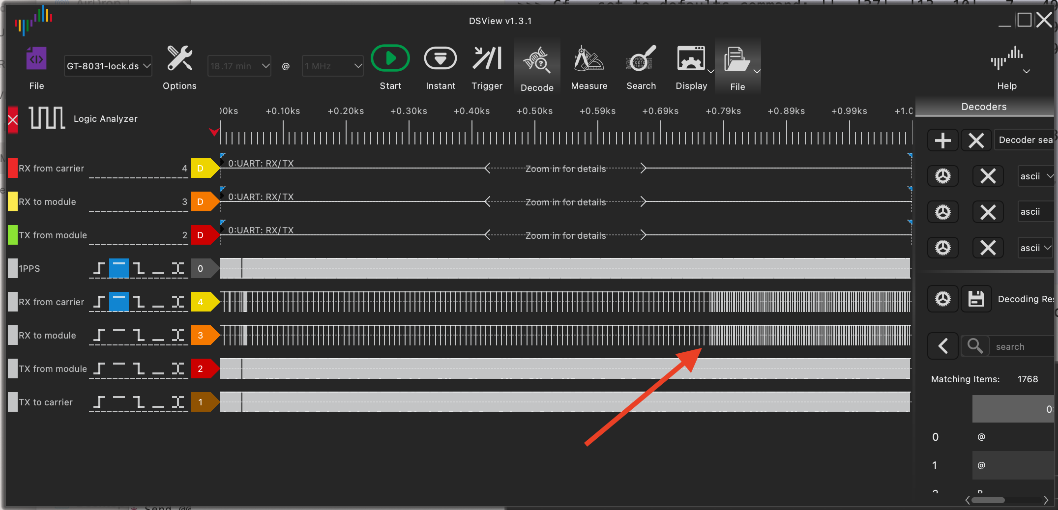
With this fix in place, it still takes almost 15 minutes before the S200 enters into GPS lock. You can see this on the logic analyzer by an increased rate of serial port traffic:
 Click to enlarge
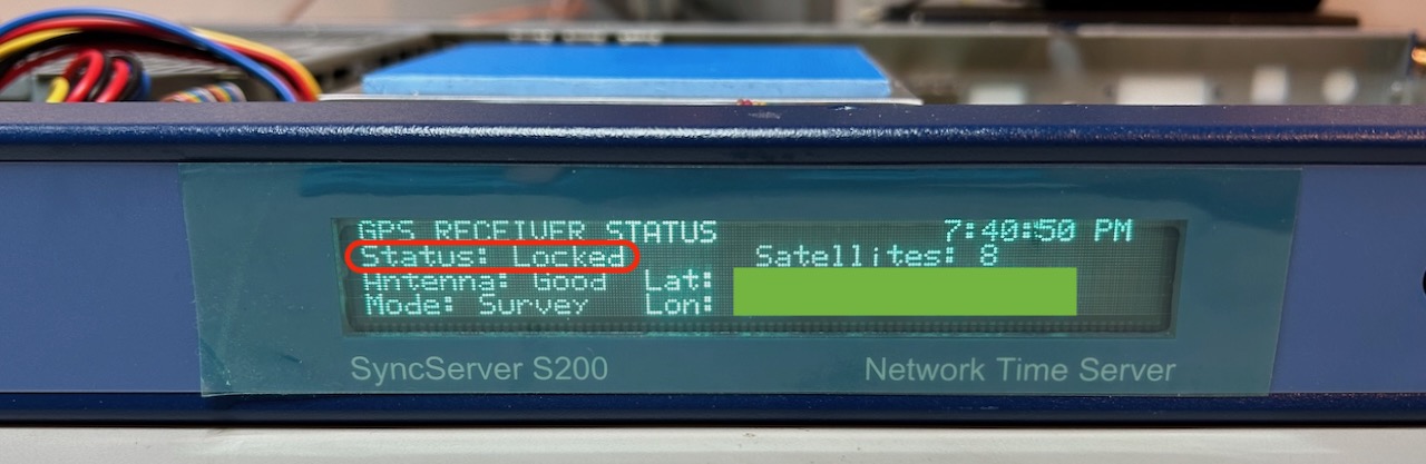
There’s also the immense satisfaction to see the GPS status changed to “Locked”:
Build Instructions
Disclaimer: it’s easy to make mistakes and permanently damage your SyncServer. Build this at your own risk!
All design assets for this project can be found in my gps_interposer project on GitHub. There is a KiCAD project with schematic, PCB design and gerber files. A PDF with the schematics can be found here. The design consists of a few connectors, some resistors and the RP2024-zero.
If you just want the Gerbers, you can use gps_interposer_v2.zip.
The interposer is connected to the motherboard and to the M12 module with 2x5 pin 0.050” connectors, one male and one female. But because it was difficult to come up with the right height of the male connector, I chose to add 2 female connectors, available here on Mouser and used a loose male-to-male connector between them to make the connection.
The trickiest part of the build is soldering 2x5 pin connectors that connects to the motherboard: it needs to be reasonably well positioned otherwise the alignment of the screw holes will be out of whack. I applied some solder past on the solder pads, carefully placed the connector on top of the past, and used a soldering iron to melt the paste without moving the connector. It wasn’t too bad.
Under normal circumstances, the board is powered by the 5V rail that’s present right next to the GPS module. However, when you plug in the USB-C cable into the RP2040-zero, you need to make sure to remove that connection because you’ll short out the 5V rail of the S200 otherwise!
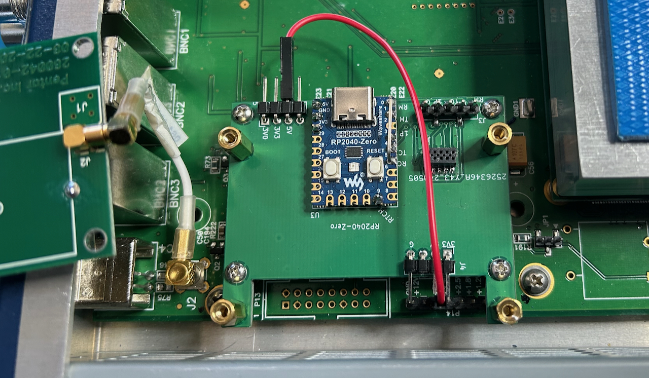
The board has 2 connectors for the 5V: at the front next to the USB-C connector and in the back right above the 5V of the motherboard. The goal was to plug in the power there, but it turned out to be easier to use a patch wire between the motherboard and the front power connector.
You’ll need to the program the RP2024-zero with the firmware of course. You can find it in the sw/rp2040_v2
directory of my gps_interposer GitHub repo.
Power Supply Recapping
If you plan to deploy the SyncServer in alway-on mode, you should seriously consider replacement the capacitors in the power supply unit: they are known to be leaky and if things really go wrong they can be a fire hazard.
The power supply board can easily be removed with a few screws.
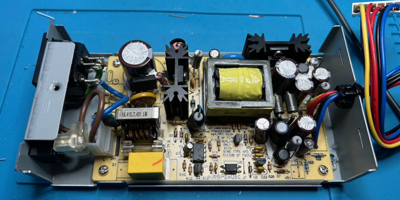
In my version, the capacitors were held in place with some hard sticky goo, so it takes some effort to remove them.
The Future: A Software-Only Solution
My solution uses a cheap piece of custom hardware. Alex’s solution currently requires patching some microcontroller firmware and then flashing this firmware with $30 programming dongle. So both solutions require some hardware.
A software-only solution should be possible though: the microcontroller gets reprogrammed during an official SyncServer software update procedure. It should be possible to insert the patched microcontroller firmware into an existing software update package and then do an upgrade.
Since the software update package is little more than a tar-archive of the Linux disk image that runs the embedded PC, it shouldn’t be very hard to make this happen, but right now, this doesn’t exist, and I’m happy with what I have.
The Result
The video below shows the 10 MHz output of the S200 being measured by a frequency counter that uses a calibrated stand-alone frequency standard as reference clock.
The stability of the S200 seems slightly worse than that of my TM4313 GPSDO, but it’s close. Right now, I don’t have the knowledge yet to measure and quantify these differences in a scientifically acceptable way.
References
- Microsemi SyncServer S200 datasheet
- EEVblog - Symmetricom S200 Teardown/upgrade to S250
- EEVblog - Symmetricom Syncserver S350 + Furuno GT-8031 timing GPS + GPS week rollover
- Furuno GPS/GNSS Receiver GPS Week Number Rollover