Measuring the HP 11720A Pulse Modulator and Coax Cables
- Introduction
- What is a pulse modulator and what are they used for?
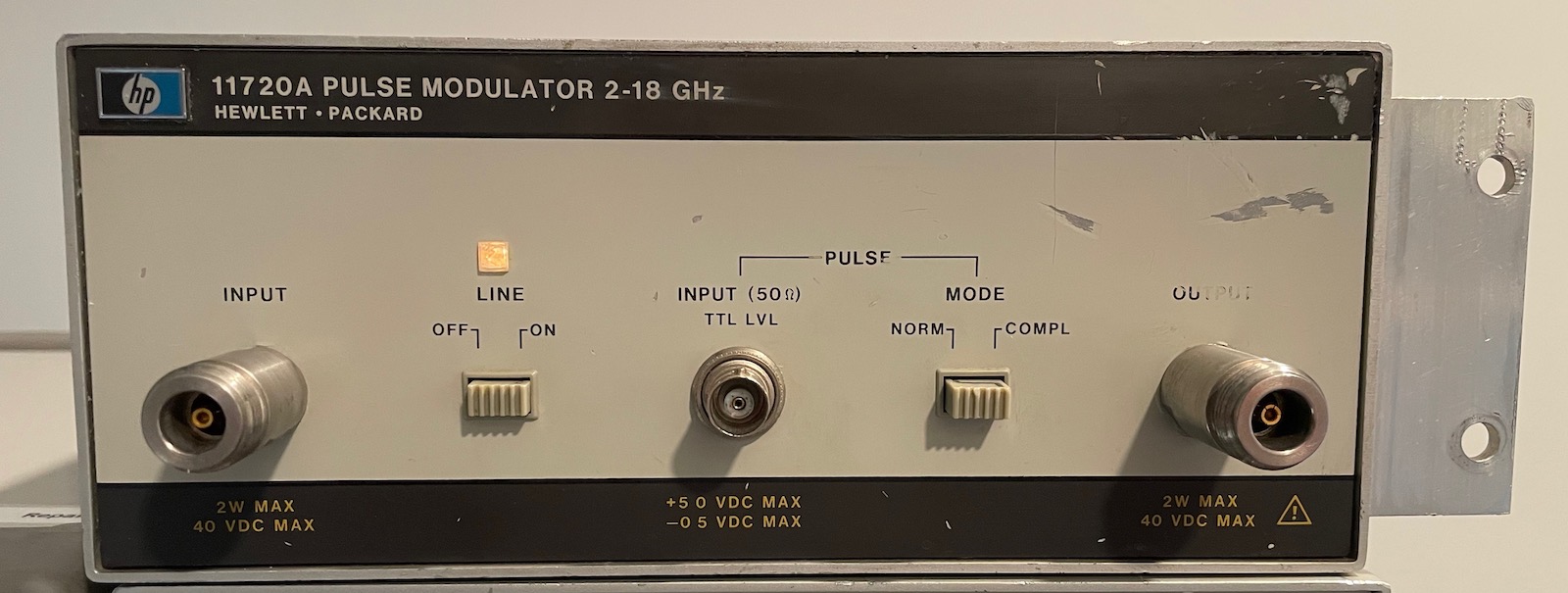
- The HP 11720A Pulse Modulator
- Inside the HP 11720A
- Measurement Setup for a Quick Testing Session
- Pin Modulator Power Measurements with HP 432A
- Cable Loss Measurements with HP 432A
- Cable Power Measurements with Spectrum Analyzer
- Final Remark
- References
- Footnotes
Introduction
Lew had 2 RF pulse modulators for sale: $25 for one, $30 for both, because his wife is asking not how much he’s able to sell this lab equipment for, but how many tons of material he has been able to get rid of.
As usual, I have no need for these things, but the price was right, and playing with test stuff is always fun. And they became essentially free by making a package deal that included an HP 423A power meter (with sensor!) and haggling the price down by $40. Everybody happy!
The first pulse modulator is an HP 11720A with supported range from 2 to 18GHz. The second one is an HP 8731B. This one has a range of 0.8 to 2.4GHz.
In this blog post, I’ll only look at the HP 11720A.
 (Click to enlarge)
After that, I’ll digress and start measuring the quality of a bunch of coax cables…
What is a pulse modulator and what are they used for?
A pulse modulator is conceptually a pretty simple device. The main input takes in a continuous-wave (CW) RF signal, one that has a constant amplitude and frequency.
A modulation signal enters through a second input and modifies the amplitude of the RF signal. In the case of a pulse modulator, the second input is usually digital, and the modulation is either completely on or off.
The output RF signal is the incoming RF signal after it has been subjected to the modulation signal.
Simple!
The HP 11720A datasheet mentions a few possible applications: pulsed radar systems, electronics warfare, and an accessory for wideband sweepers and synthesizers. It definitely sounds very cool to build my own radar, but chances are that I’ll never feel comfortable enough with RF to enter that kind of field. We’ll see…
The HP 11720A Pulse Modulator
The HP 11720A has RF type-N input and output connectors, and a BNC connector for a 50Ω-terminated 5V TTL modulation signal, though +3V is sufficient to control the output.1 On my device, the front panel says “+50 VDC MAX / -05 VDC MAX”, but after further inspection, it turns out that the decimal point has competely faded away. The actual values are +5.0/-0.5. Oops!
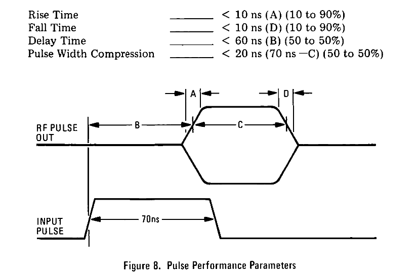
Since it’s a pure digital input, the modulation signal either passes the incoming RF signal to the output, or it switches it off entirely. The datasheet and operating manual are particularly proud about the speed by which the RF signal can be switched on or off, less than 10ns.
The RF frequency range is a pretty luxurious 2 to 18GHz, but that makes it impossible to observe the output with a regular oscilloscope. The manual suggests a solution to test the output of the modulator: mix/multiply it with an unmodulated additional RF source with the same RF frequency, and the modulation signal should come out. Since I lack a second source, I’ll be verifying the output power instead.
Speaking of power: the RF input power is listed as +20dBm (0.1W), but you can go up to +33dBm (2W) before you damage the thing. None of my RF toys come close to +20dBM, so I don’t need to worry about that. The minimum RF pulse width is 50ns, which should be fine when shooting a radar pulses to the planes that are flying over our house on rainy days.
The modulator has a loss of less than 6dB between 2 and 12.4GHz, and less than 10dB between 2 to 18GHz. That’s the amount by which the RF output level will be lower than the input.
When first released, it sold for $2600. I’m not sure when that was, but the manual was printed in 1977.
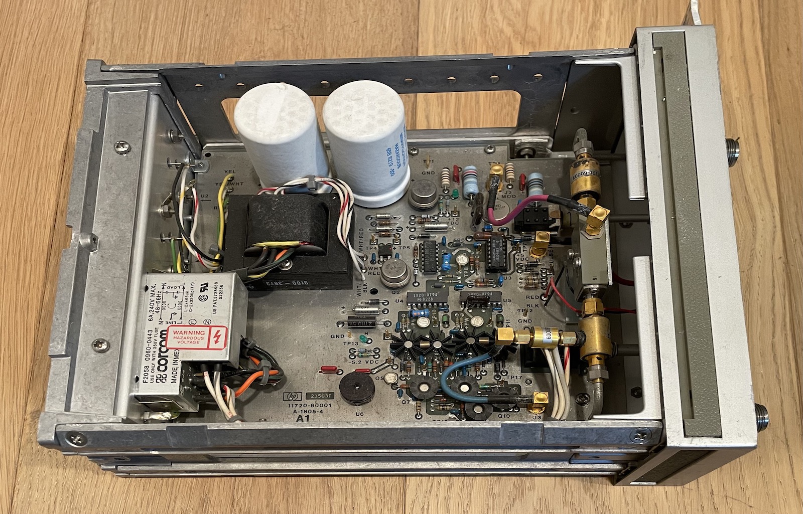
Inside the HP 11720A
 (Click to enlarge)
Like many other RF modulators, the 11720A uses a PIN diode to do the modulation. PIN, or better P-I-N, stands for P region, Intrinsic region, N region. Contrary to regular diodes than have P- and N-doped silion regions next to each other, a PIN diode has a non-doped silicon region in between.
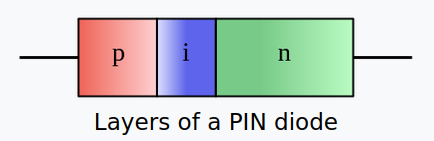
(© Georg Wiora - GFDL)
At low frequencies, a PIN diode behaves like a regular diode, but at high frequencies it behaves like a current controlled resistor. When forward biased, the resistance is about 30Ω, but when reverse biased, the resistance is thousands of Ohms. It’s the high frequency behavior that we’re interested in: in the case of the HP 11720A, it allows the modulation signal to sink the RF incoming signal to ground or not.
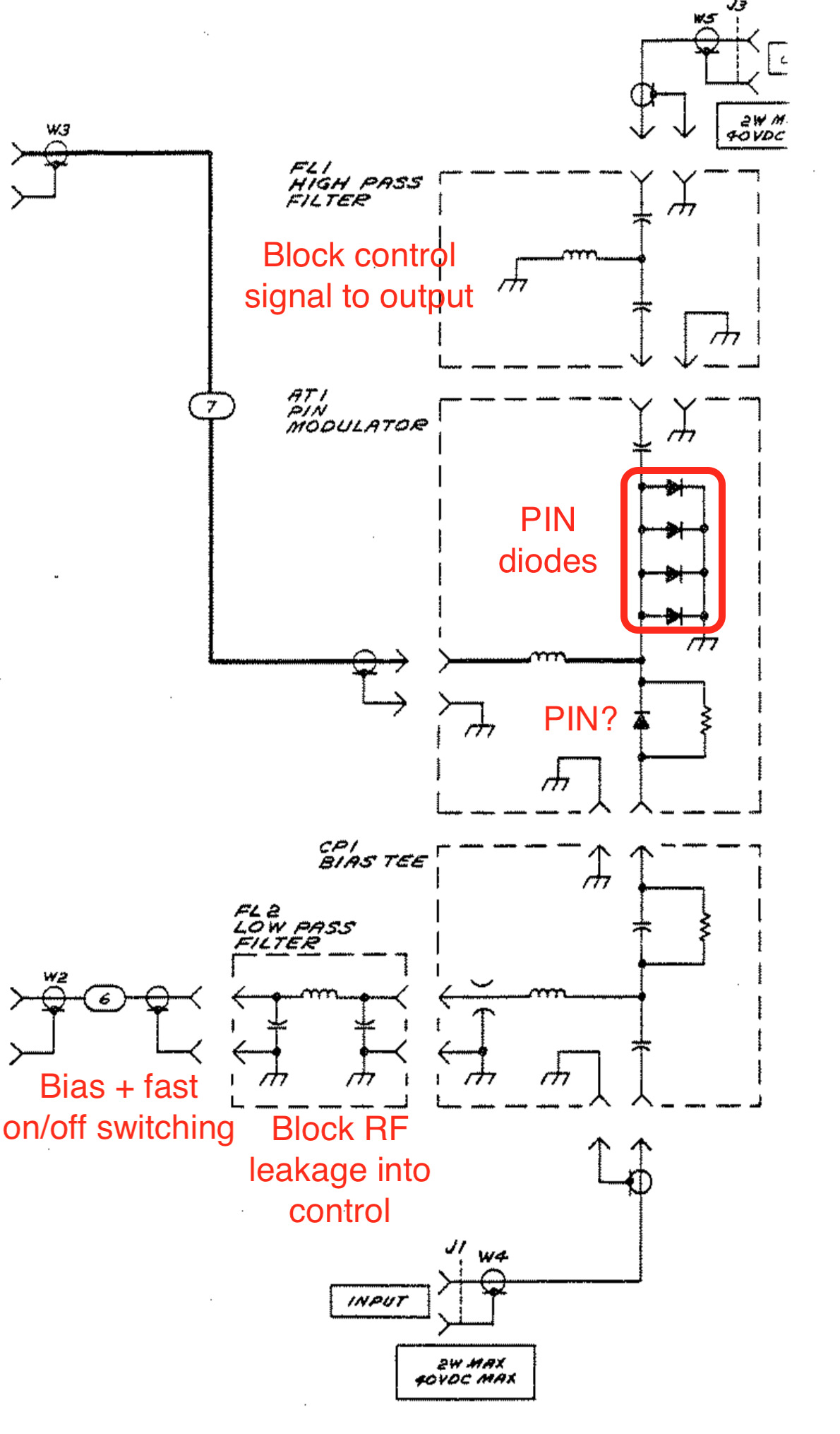
As usual for test equipment from that era, the operating and serivce manual contains the full schematic of the device, as well as a Principles of Operation section.
At the risk of making a fool of myself, here’s my own summarized and simplified understanding of how it works:
- In the schematic below, the RF signal comes in from the bottom.
- It first goes through a biasing circuit that adds a DC bias signal to the RF signal, which switches the series diode further up on or off.
- A low-pass filter prevents the incoming RF signal from leaking into the driver circuit.
- The PIN modulator itself has a series diode and a bunch of shunt diodes. (I’m not sure if the series diode is a PIN diode as well.)
- A control signal adds another bias current to switch the shunt diodes on or off.
- When the modulator passes through the signal, the shunt diodes are switched off and the series diode is switch on, and vice versa when the modulator is blocking the input signal.
- There are two control signals: the one that goes to the PIN modulator itself take care of keeping the modulator on or off. The one that goes into the BIAS circuit generates a strong pulse when the modulation switches on or off: this makes the switching action much faster, and thus allows for steeper RF on/off edges.
- Finally, a high pass filter makes sure that some of the control currents are blocked before sending the signal back out.
Here’s what the main RF actors look like in the real world:
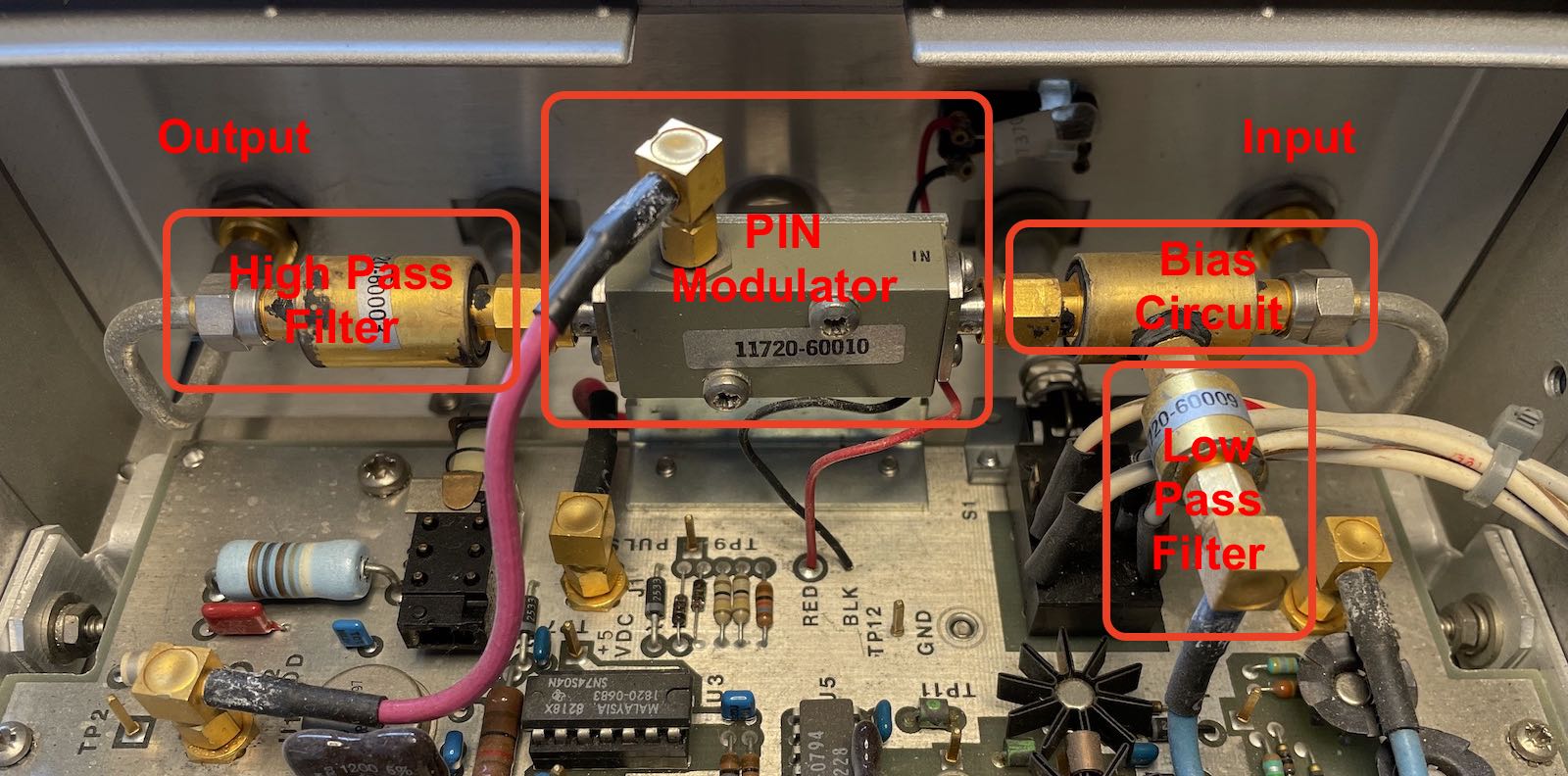 (Click to enlarge)
The control logic is relatively straightforward: a handful of logic TTL buffers, some timing logic, and drivers. Check out the manual for the schematic.
Measurement Setup for a Quick Testing Session
I created a measurement setup to test if the unit works, and how it behaves across the the frequency range.
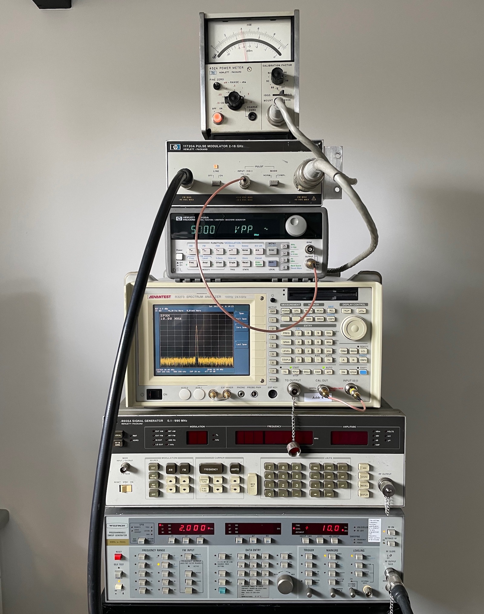
From bottom to top:
-
Wiltron SG-1206/U sweep generator
It can generate RF signals from 10MHz all the way to 20GHz, with an output of 15dBm maximum. The frequency isn’t as rock solid as you’d normally want, it can be off by 0.1% or so, but it’s more than sufficient if all you need it a signal with a frequency that’s in the general vinicity of what you want.
-
HP 8656A RF signal generator
Not used in this case: it’s maximum frequency is only 990MHz which is too low for the pulse modulator. It’s in the stack because removing it would be too much hassle. These things are heavy…
-
Advantest R3273 spectrum analyzer
It can process input signals from 100Hz to 26.5GHz. In this picture, it’s just showing a 30MHz the calibration test signal, but it can be used to do power measurement as well.
-
HP 33120A LF signal generator
The device that was raised from the dead. Here, it’s used to generate the 5V modulation signal for the pulse modulator.
-
HP 11720A pulse modulator
RF input is connected to the sweep generator. Modulation input comes from the LF signal generator. RF output is connected to the sensor of a power meter.
-
HP 432A power meter
The power meter has an HP 478A thermistor-based power sensor that is plugged in straight into the pin modulator.
When the LF signal generator is sending out a 0.4Hz TTL square wave, the power meter sees a signal going on and off:
The pin modulator is working!
In this case, the sweep generator is sending out a 3GHz/10dBm RF signal, and we’re measuring a 6.8dBm signal coming out of the pin modulator.
Pin Modulator Power Measurements with HP 432A
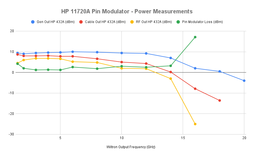
Here, the HP 432A unit is doing the power measurement, connected straight to the output of the pin modulator.
I’m using a 4ft RG-214 coax cable with N-type connectors on both sides, to connect the sweep generator straight to the pin modulator. These kind of cables very sturdy, and rated up to 11GHz, but I’m going all the way up to 20GHz.
Let’s see what happens:
| Wiltron Output Frequency (GHz) | Gen Out HP-432A (dBm) | Cable Out HP-432A (dBm) | Pin Out HP-432A (dBm) | Pin Modulator Loss (dBm) |
|---|---|---|---|---|
| 1.5 | 9.4 | 8.7 | 4.5 | 4.2 |
| 2 | 9 | 8 | 6 | 2 |
| 3 | 9.4 | 8 | 6.8 | 1.2 |
| 4 | 9.6 | 8.1 | 6.8 | 1.3 |
| 5 | 9.7 | 7.8 | 6.6 | 1.2 |
| 6 | 10 | 7.8 | 5.2 | 2.6 |
| 8 | 9.8 | 6.6 | 4.8 | 1.8 |
| 10 | 9.4 | 5 | 2 | 3 |
| 12 | 9.2 | 4.3 | 1.8 | 2.5 |
| 14 | 7 | 0.2 | -3 | 3.2 |
| 16 | 2 | -7.9 | -25 | 17.1 |
| 18 | 0.5 | -13.6 | X | X |
| 20 | -4 | X | X | X |
The first column shows the test frequencies, the second is the power output with the power sensor plugged straight into the output of the generator. Third is the power at the output of the cable. The fourth column shows the power after going through the pin modulator, and the last column shows the difference between the third and the fourth column, the loss inside the pin modulator.
 (Click to enlarge)
We’re seeing the following:
-
For all measurements, the power starts to drop above 12GHz.
This is normal: the sensor of the power meter is only rated until 10GHz. However, even above 10GHz, the meter is measuring something and we should be able to compare results relative to each other.
-
the loss in the RG-214 cable starts at 0.7dBm and steadily drops, to 4.4dBm at 10GHz, after which the loss increases rapidly.
Not unexpected for a cable that is rated up to 11GHz.
-
Finally, the pin modulator loss is 4.2dBm at 1.5GHz, but that is outside the specified range of 2 to 18GHz. From 2GHz to 14GHz, the loss is well below 4dBm, but it increases rapidly at 16GHz.
Conclusion: the HP 11720A works! I can switch the output on and off, and loss inside the modulator is within spec as well.
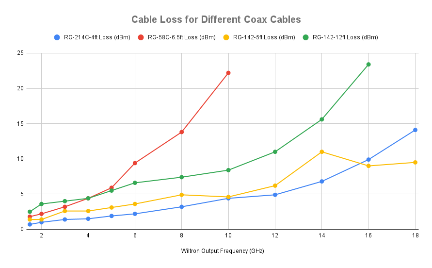
Cable Loss Measurements with HP 432A
One thing that becames quickly clear while experimenting is the importance of the type of coax cable. I was first doing measurements with a regular BNC coax, and the results didn’t make sense. I measured the power characteristics of 4 cables:
- the 4ft RG-214 coax with N-type connectors that I used above.
- a 6.5ft RG-58 coax with BNC connectors. This is basically your standard coax cable.
- a 5ft RG-142 coax with SMA connectors.
- a 12ft RG-142 coax with SMA connectors.
They are rated at 11GHz, 5GHz, 8GHz and 8GHz, respectively.
 (Click to enlarge)
We can see how the 5ft RG-142 cable is behaving better than the specifications. At the high range, it’s doing even better than the RG-214! The 12ft cable has a higher loss than its 5ft sibling, but it’s still doing an acceptable job. The RG-58C has no business doing anything above 6GHz.
| Wiltron Output Frequency (GHz) | RG-214C-4ft Loss (dBm) | RG-58C-6.5ft Loss (dBm) | RG-142-5ft Loss (dBm) | RG-142-12ft Loss (dBm) |
|---|---|---|---|---|
| 1.5 | 0.7 | 1.8 | 1.4 | 2.5 |
| 2 | 1 | 2.2 | 1.4 | 3.6 |
| 3 | 1.4 | 3.2 | 2.6 | 4 |
| 4 | 1.5 | 4.4 | 2.6 | 4.4 |
| 5 | 1.9 | 5.9 | 3.1 | 5.5 |
| 6 | 2.2 | 9.4 | 3.6 | 6.6 |
| 8 | 3.2 | 13.8 | 4.9 | 7.4 |
| 10 | 4.4 | 22.2 | 4.6 | 8.4 |
| 12 | 4.9 | 6.2 | 11 | |
| 14 | 6.8 | 11 | 15.6 | |
| 16 | 9.9 | 9 | 23.4 | |
| 18 | 14.1 | 9.5 |
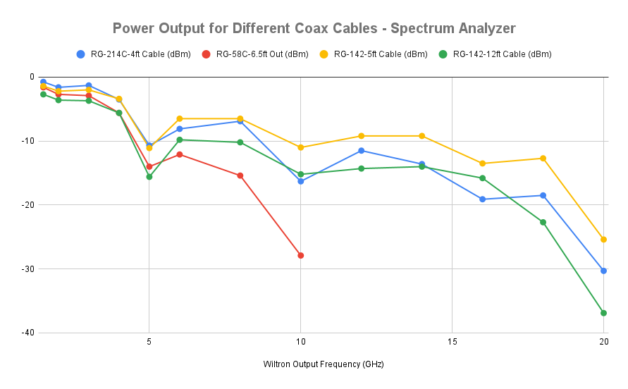
Cable Power Measurements with Spectrum Analyzer
The R3273 spectrum analyzer has the ability to measure power, so I gave that a try as well, but there’s two differences:
- I lowered the sweep generator output from 10dBm to 0dBm, to avoid out-of-range errors.
- You need to zoom in the main frequency to measure power, otherwise the spectrum analyzer doesn’t pick up the signal most of the time. This is a fundamental difference between a power meter with a thermistor, thermocouple or diode detector sensor head and a spectrum analyzer: a sensor head is wide-band and will pick up the main signal as well as harmonics, and everything in between, a spectrum analyzer does not. I chose a span of 50MHz around the main signal frequency for the spectrum analyzer measurements.
- There’s no power sensor that you can plug in straight into the output of the output of the generator. So you’re always measuring the cable as well.
Because of the last point, the data below doesn’t show the cable loss (the difference between direct output and cable output), but the absolute power that’s coming out of the cable.
 (Click to enlarge)
The graphs are more or less the opposite of the previous one, which is what one could expect.
One weird result are the numbers for 5GHz and 10GHz, where the spectrum analyzer shows a significant dip in power for all cables.
| Wiltron Output Frequency (GHz) | RG-214C-4ft Cable (dBm) | RG-58C-6.5ft Cable (dBm) | RG-142-5ft Cable (dBm) | RG-142-12ft Cable (dBm) |
|---|---|---|---|---|
| 1.5 | -0.75 | -1.6 | -1.4 | -2.7 |
| 2 | -1.6 | -2.7 | -2.2 | -3.6 |
| 3 | -1.3 | -2.9 | -2 | -3.7 |
| 4 | -3.5 | -5.6 | -3.4 | -5.6 |
| 5 | -10.7 | -14 | -11.1 | -15.6 |
| 6 | -8.1 | -12.1 | -6.5 | -9.8 |
| 8 | -6.9 | -15.4 | -6.5 | -10.2 |
| 10 | -16.3 | -27.9 | -11 | -15.2 |
| 12 | -11.5 | -9.2 | -14.3 | |
| 14 | -13.6 | -9.2 | -14 | |
| 16 | -19.1 | -13.5 | -15.8 | |
| 18 | -18.5 | -12.7 | -22.7 | |
| 20 | -30.3 | -25.4 | -36.9 |
This is even more obvious when we subtract the output of the power meter and the spectrum analyzer, and adjust for the 10dB difference in power setting:
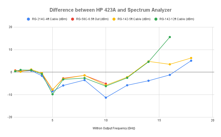 (Click to enlarge)
The power meter is only rated for frequencies up to 10GHz. Below that, the difference stays within reason for the RG-58 and RG-142 cables, except for 5GHz and 10GHz. Above 10GHz, the spectrum analyzer is still capable of measuring power, but the power meter drops off, and the difference between them increases. For the RG-214, the results start to diverge at 6GHz.
| Wiltron Output Frequency (GHz) | RG-214C-4ft Difference (dBm) | RG-58C-6.5ft Difference (dBm) | RG-142-5ft Difference (dBm) | RG-142-12ft Difference (dBm) |
|---|---|---|---|---|
| 1.5 | 0.55 | 0.8 | 0.6 | 0.4 |
| 2 | 0.4 | 0.5 | 0.2 | 1 |
| 3 | 0.7 | 0.9 | 1.2 | 0.9 |
| 4 | -1.6 | -0.8 | -0.4 | -0.8 |
| 5 | -8.5 | -7.8 | -7.7 | -9.8 |
| 6 | -5.9 | -2.7 | -2.9 | -3.2 |
| 8 | -3.5 | -1.4 | -1.4 | -2.6 |
| 10 | -11.3 | -5.1 | -5.8 | -6.2 |
| 12 | -5.8 | -2.2 | -2.5 | |
| 14 | -3.8 | 4.8 | 4.6 | |
| 16 | -1.2 | 3.5 | 15.6 | |
| 18 | 5.1 | 6.3 | ||
| 20 |
Final Remark
In addition to learning about PIN diodes, I experienced first-hand the difficulty of making reliable measurements with RF signals. It’s very easy to get incorrect results due to test setup issues. For example, when measuring the RG-214 cable with the spectrum analyzer, I got power numbers that were 30dB too low, even after tightening the cable adapters. Only after unscrewing the adapter completely and then screwing it back in, did I get reasonable results. This happened a number of times. It probably doesn’t help that all my cables and most of the equipement are sourced from Craiglist, the electronics flea market, or AliExpress. And, of course, even the more recent units, such as the spectrum analyzer, haven’t been properly calibrated in years.
So all the results here must be taken with a very thick grain of salt: they are showing trends, but they’re definitely not accurate.
References
- HP 11720A operating and service manual
- HP 11720A Datasheet
- HP App Note 58: The PIN Diode as a Microwave Modulator
- HP App Note 218-5: Obtaining Leveled Pulse-Modulated Microwave Signals from the HP 8672A
- Azur Electronis - HP 11720A Pulse Modulator
- Google sheet with measurements
Footnotes
-
I was able to make the output toggle with a level as low as 2.5V. ↩