An In-Depth Look at the ICE-V Wireless FPGA Development Board
- Introduction
- The ICE-V Wireless FPGA Board
- Preloading the PSRAM with User Data
- The Overall Boot Process
- UART Console
- Getting Started with the ICE-V Wireless Board for Real
- Reinstalling or Modifying the ESP32C3 Firmware
- The RISC-V Example FPGA Design
- Compiling the RISC-V Example FPGA Design
- Conclusion
- Footnotes
Introduction
It’s been more than 7 years now since the first public release of Project IceStorm. Its goal was to reverse engineer to the internals of Lattice ICE40 FPGAs, and create a full open source toolchain to go from RTL all the way to a place-and-routed bitstream. Project IceStorm was a huge success and started a small revolution in the world of hobby electronics. While it had been possible to design for FPGAs before, it required multi-GB behemoth software installations, and there weren’t many cheap development boards.
Project IceStorm kicked off an industry of small-scale makers who created their own development boards, each with a distinct set of features. One crowd favorite has been the TinyFPGA BX, which is still available for $38, one of the lowest prices to get your hands dirty with an FPGA that has a capacity that will exceed the needs of most users.
The BX board is very bare bones: it’s BYOP, Bring Your Own Peripherals, and there’s not even a PMOD connector for quick experimentation with external modules. That’s fine if you’re working on a custom build with physical size constraints, but you often want something with a bit more features.
The ICE-V Wireless is a relatively new entrant in this market. Developed by Querty Embedded Design, it’s available at GroupGets.com for $99. I ran into one of its creators at the 2022 Hackaday Supercon, and he gave me a board for review.
 (Photo from ICE-V Wireless github page)
Let’s check it out!
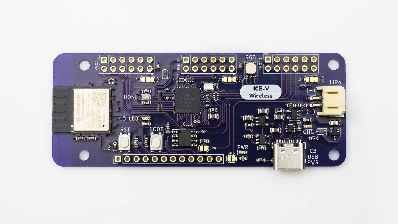
The ICE-V Wireless FPGA Board
The ICE-V Wireless GitHub project has schematics and PCB layout available in KiCAD 6.0 format. There’s also a PDF version of the schematic which is always convenient.
Let’s check out the different components:
-
ESP32-C3-MINI-1 module (datasheet)
An excellent member of the well-known Espressif portfolio. It includes:
- support for 2.4 Wifi (802.11 b/g/n) and Bluetooth 5
- a RISC-V CPU
- 4MB of embedded flash
- on-board PCB antenna
-
ICE40UP5-SG48I from the Lattice iCE40 UltraPlus family
UP5K FPGAs are used in tons of other FPGA development boards, such as the Upduino and the iCEBreaker.
It has the following key features:
- 5280 LUTs
- 128 kbits of block RAM
- 8 DSPs
- 2 I2C and SPI cores
- 1024 kbits of SPRAM
An attractive feature of iCE40 FPGA families is their low static power. This makes them well-suited for battery operated use cases.
-
LY68L6400, a quad SPI serial pseudo-SRAM (PSRAM) with a whopping 64M bits of RAM (datasheet)
The RAM is connected directly to the FPGA. It has a maximum clock rate of 100MHz. In QPI mode, with 4 data lines working in parallel, a peak transfer rate of 4MB/s should be sufficient for many applications.
-
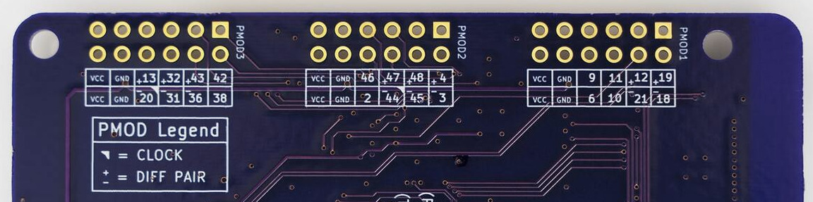
3 PMOD ports
These are your standard double-row configuation PMOD connectors with 8 GPIOs per port, all of which are controlled by the FPGA. Unusual is that the power of each PMOD can be individually selected to be either the 3v3 rail from the on-board power regulator, or the 4V/5V rail coming from USB (5V, when plugged in) or LiPo battery (4V, when present.)
A nice touch is that the PCB silk screen shows the FPGA pin number of each PMOD IO pin, as well as the polarity of differential FPGA IO pairs.
-
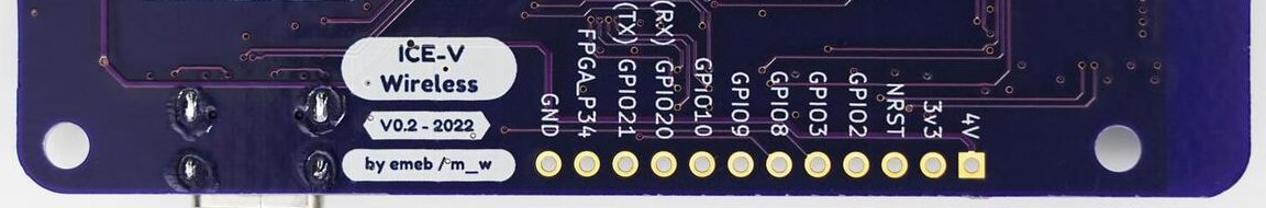
Auxiliary GPIO connector
The 8 remaining GPIOs of the FPGA and the ESP32 are routed to a 12-pin connector that can optionally be populated with a pin header. Reset, power and ground are also avaiable.
-
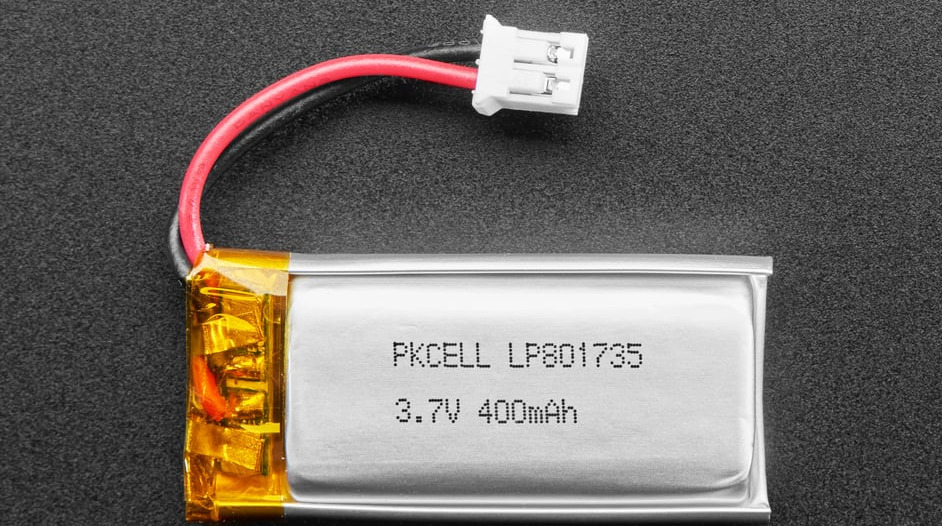
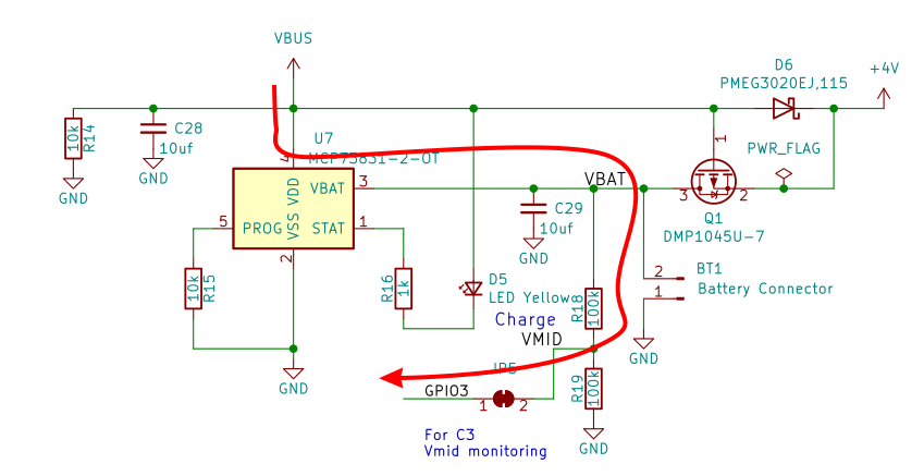
Standard LiPo battery JST connector with charging logic
It’s good to have a charge management controller on board. This one uses a Microchip MCP73831 .
Here’s such a battery, sold by Adafruit.
If there were any doubts left about the IoT/mobile intensions of this board, the inclusion of the charging logic and battery connector should put these to rest.
-
XC6222B331MR-G 3v3 LDO Power Regulator (datasheet)
This jelly bean component normally doesn’t deserve special mention, but since it also drives the PMOD power pins, it’s worth pointing out that it has a maximum output current of 700mA. If the FPGA and ESP32C3 aren’t running at full power, there should still be some juice left for peripherals.
-
USB-C Device Port
The USB-C port can be used to power the whole board. It connects to the USB port of the ESP32 module, where it can either act as serial port or a JTAG controller1.
-
Various smaller components
-
reset and boot buttons.
The boot button can be used as general purpose button for the ESP32.
-
RGB LED connected to the FPGA
The LED is not one of the ubiquitous WS2812 ‘neopixel’ family. You’ll need to implement your own PWM-based controller logic in the FPGA.
- various status LEDs
- 12MHz oscillator
-
Preloading the PSRAM with User Data
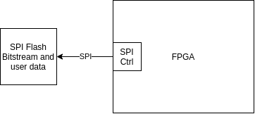
Development boards with just an FPGA are usually pretty simple affairs: there’s a SPI flash PROM on the board from which the FPGA sucks in the bitstream automatically after power up. Sometimes, there’s also a JTAG interface to directly load a new bitstream into the FPGA, but that’s not something the Lattice ICE40 family supports.
In addition to storing the bitstream, the SPI flash PROM often also contains user data that can be fetched by the FPGA as needed. A common use case is one where the FPGA has a soft-CPU core with the firmware of the CPU residing in the SPI flash.
During the bitstream loading process, the FPGA is configured in active serial mode: the FPGA is the controller of the SPI bus. After the bitstream is loaded, the FPGA remains controller of the SPI bus if it needs access to SPI user data.
Things are more complicated when there’s an SOC like the ESP32C3 on the board.
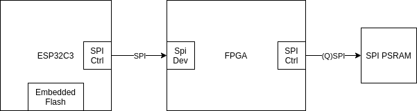
The SOC module already contains embedded flash with an SPIFFS filesystem.
It’d be a waste to add an additional SPI flash PROM just for the FPGA. Instead, the FPGA boots up in passive serial mode: during bitstream loading, the SPI port on the FPGA side is configured as a device and the ESP32C3 is the controller that copies the bitstream from the embedded flash into the FPGA.
A negative of this approach is that there isn’t a place anymore where the FPGA can fetch user data! The ICE-V Wireless board solves this by adding a (Q)SPI Pseudo RAM to the system.
This PSRAM can be used by the FPGA as pure RAM, but if the PSRAM can be pre-loaded with user data, part of it can just as well be used as pseudo flash PROM. The pseudo SRAM is a pseudo SPI PROM if you will.
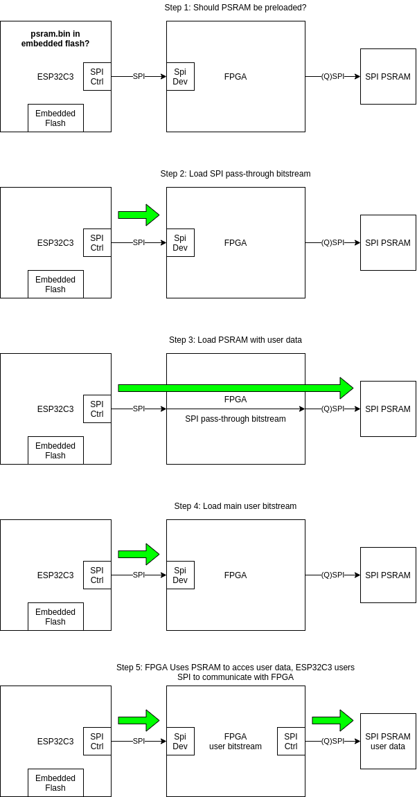
All you need then is a mechanism to get the user data into the PSRAM before the FPGA starts executing the main user bitstream. The ICE-V Wireless firmware does this with a multi-stage process:
-
the ESP32C3 first checks if the PSRAM must be preloaded with user data. It does this by checking if there exists a non-empty
psram.binfile on its embedded flash file system.If there isn’t a
psram.binfile, it jumps to step 4 and just loads the user FPGA bitstream. -
the ESP32C3 fetches a bitstream called
spi_pass.binfrom the embedded flash and loads it into the FPGA.This bitstream is completely trivial (you can check the code here). All it does is connect the ESP32C3 SPI interface to the PSRAM SPI interface.
-
the ESP32C3 fetches a binary file called
psram.binfrom embedded flash and programs it straight into the PSRAM, with the FPGA as SPI signal conduit. -
the ESP32C3 fetches the user bitstream called
bitstream.binfrom the embedded flash and loads it into the FPGA. -
configured with the user bitstream, the ESP32C3 lets the FPGA do whatever the user has programmed it to do.
If there is a need for communication between the ESP32C3 and the FPGA, it can do so through the same SPI interface. If the FPGA needs user data, it can fetch that from the PSRAM.
The default ICE-V Wireless ESP32C3 firmware has all of this implemented. The GitHub repo also has the necessary support tools to complete the flow. It’s great! However, it’s only after dissecting the firmware source code that I was able to piece the puzzle together.
The Overall Boot Process
With the details of PSRAM preloading out of the way, let’s zoom out a bit and look at the overall boot process:
- the ESP32C3 is the orchestrator of the whole process.
-
after powering up, the ESP32C3 follows the boot procedure that is described in the ESP32C3 Boot Mode Selection documentation:
GPIO9 is the bootloader select pin. On the ICE-V board, it’s connected to the BOOT button.
-
When GPIO9 is low (BOOT button pressed while releasing reset), the ESP32C3 boots from a ROM inside the ESP32C3 chip that sets up a bootloader over the USB serial port.
No matter how much you screw up your custom ESP32C3 firmware, you will always be able to reflash new firmware, such as the default ICE-V firmware, by pressing the BOOT button and releasing RESET.
-
When GPIO9 is high (BOOT button not pressed), the ESP32C3 goes in Normal execution mode.
It will first perform a bunch of internal boot housekeeping after which it loads firmware that is stored in its embedded SPI flash and execute it.
This is the normal operation. Expect to use this mode a lot, especially when you primarily use the ICE-V Wireless as an FPGA board that just happens to have an ESP32 module as well.
-
UART Console
In what’s a bit of a common theme: it’s not mentioned in any of the manual pages, but the board schematic shows how GPIO21 of the ESP32C3 has boot logging over one of its UARTs:
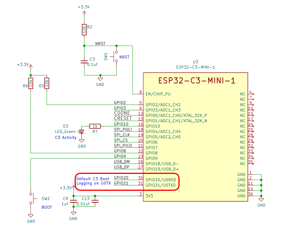
This is a standard ESP32C3 feature. I wired up a cheap
USB serial port dongle
to GPIO21 pin and connected to it with picocom -b 115200 /dev/ttyUSB0.
In boot loader mode (BOOT button pressed when releasing RST), it shows the following:
ESP-ROM:esp32c3-api1-20210207
Build:Feb  7 2021
rst:0x1 (POWERON),boot:0x7 (DOWNLOAD(USB/UART0/1))
waiting for download
And here’s what it prints out during normal boot:
ESP-ROM:esp32c3-api1-20210207
Build:Feb  7 2021
rst:0x1 (POWERON),boot:0xf (SPI_FAST_FLASH_BOOT)
SPIWP:0xee
mode:DIO, clock div:1
load:0x3fcd6100,len:0x16b4
load:0x403ce000,len:0x91c
load:0x403d0000,len:0x2d00
entry 0x403ce000
I (30) boot: ESP-IDF v4.4.2 2nd stage bootloader
I (30) boot: compile time 13:14:59
I (30) boot: chip revision: 3
I (32) boot.esp32c3: SPI Speed      : 80MHz
I (37) boot.esp32c3: SPI Mode       : DIO
I (41) boot.esp32c3: SPI Flash Size : 4MB
I (46) boot: Enabling RNG early entropy source...
I (51) boot: Partition Table:
I (55) boot: ## Label            Usage          Type ST Offset   Length
I (62) boot:  0 nvs              WiFi data        01 02 00009000 00006000
I (70) boot:  1 phy_init         RF data          01 01 0000f000 00001000
I (77) boot:  2 factory          factory app      00 00 00010000 00100000
I (85) boot:  3 storage          Unknown data     01 82 00110000 00100000
I (92) boot: End of partition table
I (96) esp_image: segment 0: paddr=00010020 vaddr=3c090020 size=16958h ( 92504) map
I (119) esp_image: segment 1: paddr=00026980 vaddr=3fc90600 size=02bb8h ( 11192) load
I (122) esp_image: segment 2: paddr=00029540 vaddr=40380000 size=06ad8h ( 27352) load
I (130) esp_image: segment 3: paddr=00030020 vaddr=42000020 size=8c434h (574516) map
I (223) esp_image: segment 4: paddr=000bc45c vaddr=40386ad8 size=09ae8h ( 39656) load
I (231) esp_image: segment 5: paddr=000c5f4c vaddr=50000010 size=00010h (    16) load
I (236) boot: Loaded app from partition at offset 0x10000
I (236) boot: Disabling RNG early entropy source...
I (241) cpu_start: Pro cpu up.
I (256) cpu_start: Pro cpu start user code
I (256) cpu_start: cpu freq: 160000000
I (256) cpu_start: Application information:
I (259) cpu_start: Project name:     ICE-V_Wireless
I (264) cpu_start: App version:      1048184
I (269) cpu_start: Compile time:     Dec 25 2022 13:15:04
I (275) cpu_start: ELF file SHA256:  0ed39813b88c943b...
I (281) cpu_start: ESP-IDF:          v4.4.2
I (286) heap_init: Initializing. RAM available for dynamic allocation:
I (293) heap_init: At 3FC97940 len 000286C0 (161 KiB): DRAM
I (300) heap_init: At 3FCC0000 len 0001F060 (124 KiB): STACK/DRAM
I (306) heap_init: At 50000020 len 00001FE0 (7 KiB): RTCRAM
Once you start changing the ESP32C3 firmware for your own applications, this kind of UART console can be worth its weight in gold.
Getting Started with the ICE-V Wireless Board for Real
When you first plug in the ICE-V Wireless board, it should immediately come up with a bunch of LEDs doing their thing:
- a red LED indicates that the board has power.
- a yellow LED will be blinking at high frequency to indicate that a LiPo battery is not connected.
- a slowly blinking green LED indicates that the ESP32C3 is not connected to a wireless network.
- a big tri-color LED, driven by the FPGA, will be cycling smoothly through the colors of the rainbow.
At the time of writing this review, the GitHub repo has a Getting Started page that will get you, well, started… eventually, but the documentation is generally lacking for a beginner. Some of the information is there, but it’s more written in the style of a reference guide.
What it needs is a tutorial with a clear, unambiguous path to go for unpacking to getting familiarized with the board.
Let’s try to fill in some of the documentation gaps.
Main Repo Installation
You always start with getting a copy of the main GitHub repo:
git clone https://github.com/ICE-V-Wireless/ICE-V-Wireless.git
Among others, the repo contains Firmware, Gateware, Hardware and python directories.
The python directory contains the tools to establish communication between
the default ESP32C3 firmware and your PC, and allows you to perform a variety of
maintenance and configuration operations.
We’ll do that first.
The Default ICE-V Wireless Firmware
The default ICE-V Wireless firmware is the one that can be found in the ./Firmware
directory. This firmware uses the ESP32C3 RISC-V CPU only as a support CPU for FPGA
bitstream bootup, the procedure that I described earlier.
- It sets up a USB serial port (on
/dev/ttyACM0on my Ubuntu 20.04 system) for PC to board communication. - After some configuration steps over USB, it also sets up a Wifi connection for
PC to board communication. - Using these communication channels, it allows you to:
- flash a user bitstream for the FPGA.
- Read and write files with data to the PSRAM on the board.
- Fetch information about battery status and IP address of the Wifi connection.
When you want to run your own custom firmware, you should try to jumpstart your development from the original firmware and keep some of the existing functionality. This will allow you to keep on using the provided tools to reflash the FPGA bitstream.
Basic Sanity Testing and Maintenance Functions
There are 3 tools in the python directory:
-
send_c3usb.pyTalks to the default ESP32C3 firmware over USB. You’ll be using this to check the battery level, check firmware version, and write files to the SPIFFS file system that resides on the ESP32C3 4MB embedded SPI NOR flash.
The SPIFFS file system contains, among other things, the bitstream that gets loaded into the FPGA at bootup.
You also use this tool to configure a Wifi network and password to which the ESP32C3 can connect to.
-
send_c3sock.pyThis tool has largely the same functionality as
send_c3usb.py, but it does its magic over a TCP/IP socket using Wifi. That’s great, because it means that you can change the FPGA bitstream over Wifi, and thus while your ICE-V board is embedded deep into whichever application you want to use it for.Of course, you can only start using this tool once you have configured a Wifi network to connect to with
send_c3usb.py. -
icevwprog.pySomething something something about loading a bitstream to the FPGA, but completely undocumented…
So let’s play around a bit:
$ cd ./ICE-V-Wireless/python
$ ./send_c3usb.py --info
Version 0.3 , IP Addr unavailable
$ ./send_c3usb.py --battery
Vbat = 4052 mV
The board is responding. Good!
I didn’t have a battery installed, but in that case, 4.052V measured is the voltage that’s driven by the LiPo charger:
Configure Wifi
Here’s the help page of ./send_c3usb.py:
tom@zen:~/projects/ICE-V-Wireless/python$ ./send_c3usb.py -h
./send_c3usb.py  [options] [<file>] | [DATA] | [LEN] communicate with ESP32C3 FPGA
  -h, --help              : this message
  -p, --port=<tty>        : usb tty of ESP32C3 (default /dev/ttyACM0)
  -b, --battery           : report battery voltage (in millivolts)
  -f, --flash=<file>      : write <file> to SPIFFS flash
  -i, --info              : get info (version, IP addr)
  -l, --load=<cfg#>       : load config from SPIFFS (0=default, 1=spi_pass
  -r, --read=REG          : register to read
  -w, --write=REG DATA    : register to write and data to write
      --ps_rd=ADDR LEN    : read PSRAM at ADDR for LEN to stdout
      --ps_wr=ADDR <file> : write PSRAM at ADDR with data in <file>
      --ps_in=ADDR <file> : write PSRAM init at ADDR with data in <file>
  -s, --ssid <SSID>       : set WiFi SSID
  -o, --password <pwd>    : set WiFi Password
I tried to configure the Wifi connection as follows:
./send_c3usb.py -s MyWifi -o VerySecretPassword
This didn’t work!
It turns that the tool can process only one command line option at a time. The right procedure is as follows:
$ ./send_c3usb.py -s MyWifi
$ ./send_c3usb.py -o VerySecretPassword
After this, you need to reset the board with the RST button. If all goes well, the green LED will start blinking vigorously at 5Hz to indicate that the ESP32C3 has successfully made a connection with your wifi network.
You can now use send_c3sock.py instead of send_c3usb.py to control the board. Like this:
$ ./send_c3sock.py --info
Version = 0.3 , IP Addr = 192.168.1.178
Success!
I’ve played a little bit with ESP Wifi modules in the past. One of the things that I found annoying was the hassle of finding the right IP address, something that can change after each reset on a DHCP configured local network.
I’m pleasantly suprised about the frictionless process of the ICE-V Wireless board. The
default firmware declares the board with a
ICE-V.local
hostname, which is also the hostname that send_c3sock.py looks for. You’ll probably have
to change this when you have multiple active ICE-V boards, but it just worked in
my case.
Reinstalling or Modifying the ESP32C3 Firmware
If you want to flash the ICE-V board with new or the original ESP32C3 firmware, you’ll need an Espressif design environment. Installation on my machine was surprisingly straight forward.
-
Download release v4.4.2 of the Espressif IDF
cd ~/tools
git clone -b v4.4.2 --recursive https://github.com/espressif/esp-idf.git esp-idf-v4.4.2
Keep an eye on the ICE-V Firmware README if you want to do this yourself: it’s always possible that the ICE-V firmware will require a different version for newer firmware releases.
-
Install the ESP32C3 version
cd ~/tools/esp-idf-v4.4.2
./install.sh esp32c3
This will download and install a whole bunch of files in the
~/.espressifdirectory. -
Set up your
$PATHto include the Espressif toolscd ~/tools/esp-idf-v4.4.2 . ./export.shYou might want to add that last line to your
~/.profilefile, but I prefer to just run it in that one terminal window where I plan to do firmware builds. -
Compile the ICE-V Wireless firmware
cd ~/projects/ICE-V-Wireless/Firmware
idf.py build
This will kick off a bunch of compilations. If all goes well, you’ll be greeted by this message:
Project build complete. To flash, run this command: /home/tom/.espressif/python_env/idf4.4_py3.8_env/bin/python ../../../tools/esp-idf-v4.4.2/components/esptool_py/esptool/esptool.py -p (PORT) -b 460800 --before default_reset --after hard_reset --chip esp32c3 --no-stub write_flash --flash_mode dio --flash_size detect --flash_freq 80m 0x0 build/bootloader/bootloader.bin 0x8000 build/partition_table/partition-table.bin 0x10000 build/ICE-V_Wireless.bin 0x110000 build/storage.bin or run 'idf.py -p (PORT) flash' -
Flash the firmware
idf.py -p /dev/ttyACM0 flashThat’s really it!
I expected that I’d have to press the BOOT button and do a RST before I’d be able to flash the firmware, but that was not needed.
It would go too far to get into all the details of developing for the ESP32C3, but Espressif provides a ton of development documentation about just that.
The RISC-V Example FPGA Design
The visual effect of the example bitstream is trivial, the LED just cycles through all colors, but the design behind it is elaborate.
It’s a small SOC that contains:
- a picorv32 RISC-V soft-CPU
- a UART
-
an SPI device that goes to a number of registers and a mailbox FIFO.
This allows the ESP32C3 to interact with the soft-CPU.
-
2 SPI controllers
The UP5K FPGA has 2 hard-macro
SB_SPIcontrollers. I don’t think I’ve ever seen them being used in the past, but this SOC instantiates both of them and even has a SW driver.The PSRAM is connected to one of these SPI controllers. There’s a driver for that too.
-
an I2C controller
Like the SPI controllers, the UP5K also has a hard-macro
SB_I2Ccontroller. It’s instantiated in the example design as well, again with a SW driver. - a PWM controller for the LEDs
The toplevel file of the design can be found here: here.
While it’s nice to have a complex design example to show off the possibilities, it can also be a bit overwhelming, especially since nothing about the design is documented. It’d be easier for a new user to have multiple smaller examples of increasing complexity.
The ICE-V Wireless board authors have been adding new examples that can be found in the main Gateware directory.
Compiling the RISC-V Example FPGA Design
Let’s go through the motions to compile the most complex example.
-
OpenFPGA toolchain installation
The Yosys Open Source CAD suite contains all the tools needed to build an FPGA bitstream. It used to be a lengthy compilation process, but these days you can just download a release that contains everything.
The commands below install the tools exactly where the ICE-V Gateware development environment expects it. If you want to install it somewhere else, you’ll need to modify the Makefile to point to the right location, or set the way-to-generic
TOOLSenvironment variable with the right value.cd ~/Downloads wget https://github.com/YosysHQ/oss-cad-suite-build/releases/download/2022-12-26/oss-cad-suite-linux-x64-20221226.tgz sudo mkdir -p /opt/openfpga/ cd /opt/openfpga sudo tar xfvz ~/Download/oss-cad-suite-linux-x64-20221226.tgz sudo mv oss-cad-suite/ fpga-toolchain -
Install another RISC-V toolchain
A RISC-V C compiler is required to compile the source code of the
picorv32soft-CPU.In theory, you should be able to reuse the RISC-V compiler that’s part of the ESP32C3 development environment, it uses a RISC-V CPU as well, but that’s not what’s done here. The Gateware build uses the pre-compiled August 2019 RISC-V toolchain from SiFive:
cd ~/Downloads wget https://static.dev.sifive.com/dev-tools/riscv64-unknown-elf-gcc-8.3.0-2019.08.0-x86_64-linux-ubuntu14.tar.gz sudo mkdir -p /opt/riscv-gcc cd /opt/riscv-gcc sudo tar xfvz ~/Downloads/riscv64-unknown-elf-gcc-8.3.0-2019.08.0-x86_64-linux-ubuntu14.tar.gz -
Build the RISC-V example
cd ~/projects/ICE-V-Wireless/Gateware/icestorm
make
After a minute or so, you should see this:
Info: Program finished normally.
/opt/openfpga/fpga-toolchain/bin/icepack bitstream.asc bitstream.bin
A new
bitstream.binis waiting! -
Program the new bitstream into the ESP32C3 embedded flash
cd ~/projects/ICE-V-Wireless/Gateware/icestorm
../../python/send_c3usb.py -f bitstream.bin
Programming takes only a few seconds.
-
Reset the board
If all goes well, you should see the newly flashed bitstream in action.
To revert back to the default bitstream, you can do this:
cd ~/projects/ICE-V-Wireless/Firmware/spiffs
../python/send_c3usb.py --flash bitstream.bin
Conclusion
I have a stack of different FPGA boards, spanning the range from the extremely basic Cyclone II EP2C5 to the seriously complicated Kria KV260. When developing new code, I choose the board that best fits the needs for a project. The same design will compile faster on a smaller FPGA than on a larger one.
Despite years of doing FPGA hobby projects, I’ve rarely exceeded the capacity of a UP5K FPGA. And when I got close, it was always because the design contained a soft-CPU, something that wouldn’t be needed if there had been a CPU like the one in an ESP32C3.
The ICE-V Wireless board is a great option for those who’d like to experiment with an embedded system like the ESP32C3 and combine it with the lower level aspects of an FPGA. It’s of course also perfectly usable for those who just want to play with FPGAs.
The ICE-V Wireless board plays in the class of smaller FPGA boards, flanked at the lower end, both in features and price, by the $50 TinyFPGA BX, the $70 iCEBreaker, and the $30 Upduino, and at the upper end by the $135 ULX3S-ECP5-12F.
Due to presence of the ECP32C3 module and the PSRAM, it’s fair for it to be priced higher than the lower end. Its biggest struggle might be the $35 price distance with the higher end: the ULX3S-ECP-12F not only has an FPGA with more than double the resources, its PCB also has a bunch of peripherals and connectors that are lacking on the ICE-V Wireless.
A constant thread through this review is the lackluster state of the documentation. While the tools, the firmware, and the example design bring out the best of the board, much of it is not documented, and requires going through the source code to be discovered.
Luckily, that’s a problem that’s easy to fix and one that is being addressed by the ICE-V creators.
In short, if you’re looking to buy one FPGA board and you have a budget of $100, the ICE-V Wireless should be high on your list.
I have one ICE-V Wireless board to give away for free. Send an email to icev.wireless.giveaway@gmail.com
to enter. On January 1, 2023, I’ll draw a winner at random. Entrants must have a US post address. The
giveway has concluded. Congratulations to Sean!
Footnotes
-
It can act as a JTAG controller for the ESP32C3 JTAG port, for things like connecting to the CPU debug logic. There is no JTAG port on any iCE40 FPGA. ↩