Under the hood of Formal Verification
Table of Contents
- Table of Contents
- Why Formal Verification?
- What Is Formal Verification?
- Open Source Formal Verification with SymbiYosys
- An Example with a Workaround
- Components of the SymbiYosys Formal Flow
- Synthesizing a Design with Formal Verification Statements
- SystemVerilog Assertions
- A Simple but Non-Trivial Sequence
- A Working (but Ultimately Useless) Implementation
- Finite State Machines to the Rescue
- From Non-Deterministic to Deterministic FSM
- Handling Parallel Sequence Evaluation
- Intermediate Conclusion
- Advanced Formal Support in Yosys Already Exists
- Call to Action
Why Formal Verification?
(If you’re reading this blog post, chances are high that you can just skip this section…)
Design verification has always been more important and harder for digital hardware than for software.
Software has a very linear progression where one instruction gets executed after the other and behavior is purely data dependent: given the same input, you should get the same output. Things get a bit more difficult when multiple threads are involved, but even there the amount of things going on in parallel can be counted on one hand.
Meanwhile in digital hardware land, almost everything happens in parallel. Thousands or millions of flip flops are toggling at the same time and often interacting with the same limited resource: arbiters can only serve one request at a time, RAMs typically have at most 2 read and/or write ports etc.
So not only do you have the data dependent behavior of software, but you also have an extremely strong sensitivity to timing. A bus arbiter that grants access an external DRAM might have 8 inputs, and your simulation might stress cases where up to 7 of those inputs are requesting access to memory during the same clock cycle and things are working great. But in that extremely rare case where 8 inputs are active at the same cycle, a bug is triggered, and your design fails.
In a production environment, that situation might happens about once every two days, even if the arbiter is running at 1GHz. In other words: it’s something that will only happen once every 172E12 clock cycles!
The reason of this bug might be a vector that contains the number of active requestors at any point in time which was sized with 3 bits, good for 0 to 7 concurrent active agents, instead of 4 bits. One of those dreaded off-by-one bugs…
Competent verification engineers are worth their weight in gold: they will identify a case like this up front. They will add a test case in the test plan. They will add a cover point in the code. And they’ll go through the coverage reports to make sure that said cover point has been triggered during one of the simulations.
If necessary, they will create a few targeted vectors that trigger the problem case, and they will guide the random stimuli generator with constraints that guide a test case towards such high input activity cases.
Without a human explicitly identifying this problem case, not many traditional tools will detect this kind of vector overflow as an issue: at best, your RTL linting tool might warn that 8 one-bit signals added together will require a 4 bit result. But that real warning will often appear in a sea of harmless false positives.
And, of course, the problem sketched here is actually a very simply one. One that triggers a bug when 8 orthogonal signals assert at exactly the same time, so not that complicated to identify up front as a problem case to begin with.
Similar issues can hide in intricate pipelines for which problem conditions are much harder to imagine.
There must be a better way, and, luckily, there is.
The solution is formal verification.
What Is Formal Verification?
With formal verification, instead of simulating your design and hoping for the best, you provide constraints that are supposed to be true or false at any point in time. And you use a solver to prove that, under no circumstances, these constraints are ever violated. If there is a way to violate one or more constraints, the solver will generate a waveform that shows exactly how the error case can be triggered. It is then up to the designer to fix that bug, either by changing the design or by changing the constraints.
That’s the elevator pitch.
In practice, there’s quite a bit more to it. There are different ways and techniques. There are limitations in the tools. There are fundamental limitations as well, where from a pure mathematical point of view it’s simply impossible to prove design correctness because it would take too long. Formal proofs are an NP complete problem after all.
Despite this limitation, formal verfication can be extremely powerfull. The knowledge that design correctness is proven with 100% certainty, instead of just assumed due the amount of random design vectors that have been thrown at it, is irresistible.
In addition to proving the correctness of a design, formal verification tools can also be used
to come up with waveforms that take a design from initial state to a desired state, by using
cover statements. This can be extremely helpful at the start of project as an alternative
to writing a directed test bench: in stead of explicitly guiding a design under test to
a desired outcome, you let the formal tool figure things out by itself.
Open Source Formal Verification with SymbiYosys
Formal verification is nothing new: commercial tools have existed for decades. But an easy to use open source alternative that can load a Verilog design with some constraints did not exist.
That was until the release of SymbiYosys. Written by open source All-Star Clifford Wolf, SymbiYosys links your Verilog design with formal commands to a SAT solver. SymbiYosys itself is a script around Yosys, the widely used open source logic synthesis tool.
Open source SymbiYosys only offers a small set of what is available commercially, but it is still a enormous step forward: it covers the essential basics which can serve as a foundation on which more complex flows can be built.
Specifically, SymbiYosys’ formal verification features are restricted to proving purely boolean
equations only (with some limited temporal additions such as $past and $stable) whereas full
featured tools support a rich set of primitives such as temporal sequences and implications.
In other words, the formal statements only allow checking things that happen in the current cycle, not what happened over a sequence of clock cycles.
That doesn’t mean that you can’t verify sequences, but you need to design additional logic to do so.
An Example with a Workaround
Here is a real example not only of how the formal cover statement can be used to create
a test case with minimal effort, but also how SymbiYosys is currently limited in terms of
capabilities and how to work around it:
I’m in the process of designing UlpiCtrl,
a block that converts CPU reads and writes on an APB bus into ULPI
transactions. (ULPI is a standard interface to control USB PHY chips. It’s similar in nature to MII
interfaces for Ethernet PHYs.)
To transmit a packet, the intended use case is the following:
- Write all packet bytes to a transmit FIFO.
- When done, write to a
TX_STARTaction bit. - Wait until the FIFO is completely empty. This indicates that the packet has been fully transmitted.
One could write a traditional testbench to simulate such a case, but that’s pretty boring.
It’s much faster to use the formal cover statement to do this for you.
This statement, written in SpinalHDL, does exactly that:
    cover(!initstate() && reset_
                && tx_data_fifo_level_reached
                && (ulpi_ctrl_regs.apb_regs.u_tx_data_fifo.io.pushOccupancy === 0)
The cover statement has 3 terms that must be satisfied to get a meaningful result:
- Boilerplate to ensure that you don’t get some false positive during reset:
cover(!initstate() && reset_ - the transmit data FIFO must have reached a fill level of at least 10 at some point in the past:
&& tx_data_fifo_level_reached - the transmit data FIFO must currently be empty
&& (ulpi_ctrl_regs.apb_regs.u_tx_data_fifo.io.pushOccupancy === 0)
When you run this through SymbiYosys, this very simple 3-line statement will generate a VCD waveform of ~25 clock cycles that will do every necessary to satisfy the condition inside the parenthesis of the cover statement. The result looks like this (click to enlarge):
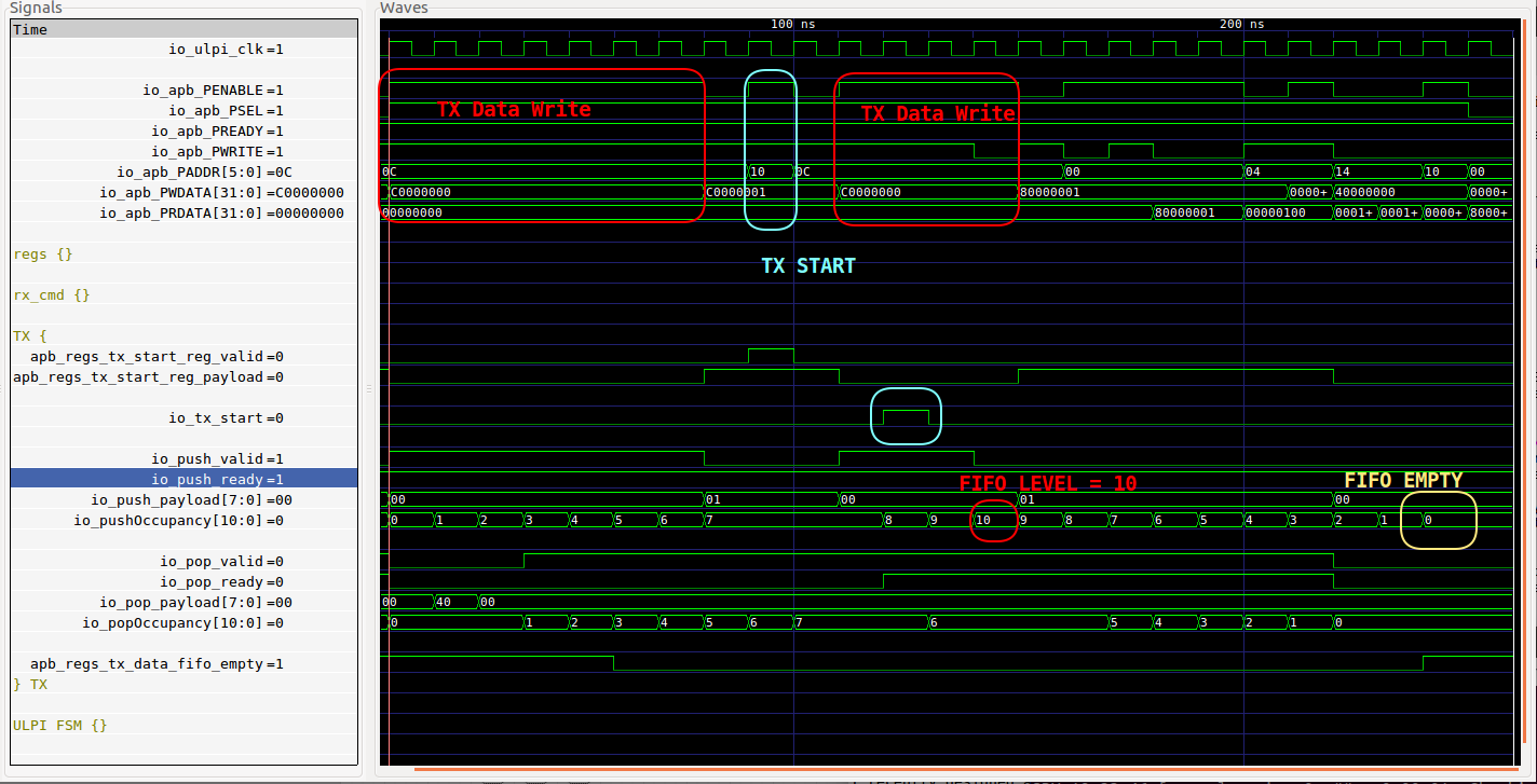
It’s truly a thing of magic!
There are 10 TX DATA write operations, there’s 1 TX START write operation, and the waveform ends when the FIFO reaches a level of 0.
One can see how the write to TX START happened in the middle of a sequence of TX DATA writes instead of at the very end. That was certainly not the intention, but we never constrained the design to avoid this either. One of the characteristics of formal verification is that the tool will try to achieve something any which way it can, even if the scenario isn’t what you had in mind. This is a good thing!
The most important point is that I did not need to write an APB bus master. I did not have to write a ‘for’ loop to issue 10 APB writes to the tx_data FIFO write register. Neither did I have to issue a write to the TX_START register, or write a polling loop to check that the FIFO was empty.
None of this was necessary because the only way to satisfy the cover condition above is by doing those steps anyway. The formal tool had no other choice but to come up with those operations itself!
But there is a minor issue with this example: the second term of the boolean equation is not something that’s part of the real design. It is helper logic that was added specifically to make this cover statement work:
    val tx_data_fifo_level_reached = RegInit(False)
            setWhen(ulpi_ctrl_regs.apb_regs.u_tx_data_fifo.io.pushOccupancy === 10)
tx_data_fifo_level_reached is a flip-flop that starts out at 0 and that goes 1 and stays 1 when the tx data FIFO reaches the
desired fill level for the first time.
It’s not a big deal to add this statement, but it is needed to work around the fact
that cover only supports pure in-the-moment boolean equations. As soon as temporal behavior needs to be
checked, you need to improvise.
And those improvisations can get ugly pretty quickly.
What if you want to write a cover case where you want to check 2 or more packets to be transmitted, using exactly the same operations that were mentioned above. Now you’ll need to implement some counter that goes up each time a level of 10 is reached. But maybe you want to transmit 10 bytes for the first packet and 1 byte for the second? That makes the test case harder.
This would be totally acceptable if there were no better solutions, but better solutions do exist. They’re just not available for open source tools.
Components of the SymbiYosys Formal Flow
Before diving deep into these advanced features, let’s first have a quick look at what makes SymbiYosys tick and check out its different components:
-
SAT solver
A tool that is used to prove that there exists a solution to a boolean formula.
The pure boolean equations obviously map directly to combinatorial logic gates (AND, OR etc). But they can also can contain state elements that can be assigned new values that become active the next cycle. These map directly to flip-flops.
All while observing the constraints of the design, the SAT solver tries to prove that a particlar rule will always be satisfied, or it can figure out which inputs need to be applied to a boolean network to make a particular equation true.
There are a bunch of different open source SAT solvers, each with their own strengths and weaknesses. One thing that they have in common is that they support a common input format: SMT2.
-
Yosys
Yosys is an open source synthesis tool by the same author as SymbiYosys. It is very modular, with different frontends to read in new designs (Verilog, blif, json, Synopsys liberty, …) that ultimately converts the input design to an RTLIL (RTL Intermediate Language) representation.
Yosys has a ton of transformational passes that convert one RTLIL representation into another. These passes are optional and are selected based on what’s needed: when synthesizing to an FPGA, one might use a pass that specifically targets LUTs, with a few advanced optimization passes thrown in as well. But for other uses, such as formal verification, one might avoid logic optimization completely to have an as close as possible match between the original design and RTLIL.
Finally, there are bunch of backends that convert the final RTLIL design into the desired format: Verilog, edif, json, … One of these supported format is SMT2.
Yosys is under very active development. New optimization passes are being added all the time, technology libraries are being created or improved. Bugs are being fixed in frontends, error message become more descriptive, etc.
-
SymbiYosys
With Yosys really doing all the heavy lifting, SymbiYosys is a collection of Python scripts that make it easier to get a formal verification run going. It defines a configuration file format that allows one to gather various options and the different files that will be needed. It creates the necessary directories, copies around files, launches Yosys and the SAT solver and provides clean feedback to the user.
While extremely useful for somebody who wants to practice formal verification, the SymbiYosys source code isn’t particularly interesting.
Synthesizing a Design with Formal Verification Statements
Let’s start with a very simple design:
module demo1(
    input clk
    );

    reg reset_;

    initial reset_ = 1'b0;
    always @(posedge clk) reset_ <= 1'b1;

    reg [1:0] cntr;
    always @(posedge clk) begin

        if (cntr == 2)
            cntr <= 0;
        else
            cntr <= cntr + 1;

        if (reset_) begin
            cntr <= 0;
        end
    end

    assert property($initstate || !reset_ || cntr != 3);

endmodule
We’re testing that a 2-bit counter will never reach a value of 3.
After running SymbiYosys on this (sby -f demo1.sby), we end up with, among others, the
design.ys, design_smt2.ys and design_smt2.smt files.
design.ys converts the Verilog file into an RTLIL format:
# running in demo1/src/
read -formal demo1.sv
prep -top demo1

memory_nordff
async2sync
chformal -assume -early
chformal -live -fair -cover -remove
opt_clean
setundef -anyseq
opt -keepdc -fast
check
hierarchy -simcheck
write_ilang ../model/design.il
The most important statement above is the chformal ... -remove one: depending on the kind of operation that will be performed
by the SAT solver, it will remove certain formal statements. In this case, I opted for bounded model checking so checks for
liveness, fairness, and cover were removed.
The second script design_smt2.ys converts your Verilog file into an SMT2 file:
# running in demo1/model/
read_ilang design.il
stat
write_smt2 -wires design_smt2.smt2
The SMT2 language specification
is a 45 page document with tons of different commands, but the file that’s generated by SymbiYosys uses only
3 of those: declare-sort,declare-fun and define-fun.
The SMT2 file is created with the write_smt2 command. A quick look at
the source of this Yosys backend shows
that generating an SMT2 file is a pretty lightweight operation: the original Verilog file was synthesized
into a limited set of boolean operations which are then easily converted to some SMT2 equivalent.
For those who are interested, the manual of the write_smt2
command has a detailed description of the structure of the generated SMT2 file.
When looking at formal specific features in the Yosys Verilog frontend, the list is very short indeed: some Verilog lexer definitions, their associated Verilog grammar rules, and finally the instantiation of the corresponding cells into the RTLIL representation.
And that’s really it!
The real heavy lifting in the process of formally proving a design is done by the SAT solver.
The biggest take-away of the section is pretty straightforward but also very fundamental:
The SymbiYosys formal tool flow is entirely based on the ability to synthesize a Verilog design.
But also:
Advanced formal features can be added without issue as long as they can be described in synthesizable Verilog!
Before everybody gets their hopes up: the end of this post will not contain a great reveal of the Next Great Open Source Formal Verification Tool. Instead, it dives into lower level specifics of how such a thing might be implemented under the hood.
SystemVerilog Assertions
What we really want is support for temporal assertions.
SystemVerilog has had them for something like 15 years.
You can find a quick overview of what they can do on this Doulos tutorial page, but it’s essentially a very compact way to describe sequences of events.
The example above could have been written like this:
    property p_fifo_tx;
        @(posedge clk)
            (ulpi_ctrl_regs.apb_regs.u_tx_data_fifo.io.pushOccupancy === 10)
                ##[1:$] (ulpi_ctrl_regs.apb_regs.u_tx_data_fifo.io.pushOccupancy === 0);
    endproperty

    cover property(p_fifo_tx);
This first defines a particular property that contains a sequence. It then checks that this property gets covered at least once.
IMPORTANT: this code, and similar examples further below, may not compile or execute correctly for a variety of syntactical or sematic reasons, because there is no open source tool to check them!
SystemVerilog sequences provide a rich set of operation to schedule events in succession, to repeat such sequences, to wait for something to happen a certain amount of times, to add implications etc.
In the simple example above, it waits for the FIFO to reach a level of 10, then the ##[1:$] operator
tells it to wait between 1 and infinite amount of cycles until the FIFO empty condition is reached.
If we wanted to create a case where 2 packets are transmitted in succession, we could add the following cover statement:
cover property(p_fifo_tx[*2]);
A Simple but Non-Trivial Sequence
Let’s abandon the ULPI controller example, and switch to another example that will give us a feel of some of the problems that need to be solved under the hood.
sequence a_seq_b12_seq_c
    a ##1 b[*1:2] ## c
endsequence
This sequence results in a match when the following happens:
- ‘a’ evaluates to 1
- after that ‘b’ evaluates to 1 for one or for two consecutive clock cycles
- after that, ‘c’ evaluates to 1
Here are some examples of matching waveforms:

The first 2 are exactly as one would expect: ‘a’ followed by one or two ‘b’ followed by ‘c’.
The third one shows something important: a single sequence can result in multiple matches! It matches a case where first ‘c’ follows both a single ‘b’, and the second ‘c’ follows two ‘b’s.
The fourth waveform shows that sequences can run in parallel. The first two successful (“OK!”) matches were initiated by the first ‘a’ pulse, while the third successful match was initiated by the second ‘a’ pulse. However, the second ‘a’ pulse started while the first sequence was still evaluating.
A Working (but Ultimately Useless) Implementation
Let’s cook up some RTL code that implements this kind of sequence.
    assign a_vec[2:0] = { a_dly[1:0], a };
    always @(posedge clk) begin
        a_dly[2:0] <= a_vec[2:0];
    end

    assign b_vec[1:0] = { b_dly[0], b };
    always @(posedge clk) begin
        b_dly[1:0] <= b_vec[1:0];
    end

    assign match_seq_a_b = (a[1] && b[0]) || (a[2] && |b[1:0]);

    always @*(posedge clk) begin
        match_seq_a_b_dly <= match_seq_a_b;
    end

    assign match_seq_ab_c <= match_seq_a_b_dly && c;
I haven’t tested this, but it should probably work! I’m using delay lines and detect individual cases. And this works great because with a delay line, I can have events and detect matches in parallel.
The problem is: this kind of solution is limited to very simply cases only. The main issue is that SystemVerilog sequences can be nested and they can be infinite.
You can do this: seq_a ## seq_b or seq_a[*1:5] ## seq_b, which would get complicated
real quick.
You can also do this: seq_a ##[3:$] seq_b: this matches when seq_a is followed by seq_b after
3 or more (without any limitation) clock cycles.
Detecting infinite length sequences by using delay lines is just not very practical.
Finite State Machines to the Rescue
Let’s quickly forget the previous solution and move on to what should have been obvious from the start: we have something that progresses from one state to the next based on some external condition. This just smells like something that done with a finite state machine.
The first quick sketch on our napkin looks like this:

‘a’, one or two ‘b’s, and then a ‘c’. Simple.
But the traditional FSM that we know and love only has one active state at a time. And we’ve learned earlier that a single ‘a’ can result in multiple ‘c’s. And we also know that multiple sequences can be evaluated in parallel.
Something will have to be done to make all of that work. But let’s first make the diagram a bit more rigorous by annotating the different state transitions.
There are 3 different external inputs, a,b, and c, good for 8 different combinations. Let’s number them that way. And for each state, let’s also annotate the outgoing transitions with the input combinations that will trigger each transition.
You get something like this:

To move from the first to the second state, ‘a’ must be 1. This corresponds to input combinations 1,3,5 and 7.
You see 2 transitions out of the “First B hit” stage that get triggered by the same input combinations 6 or 7. That is the problem that will need to be solved.
Whenever the FSM is in a certain state and none of the input combinations match one of the outgoing transitions, the FSM aborts, meaning that there was no match was possible for that sequence.
The two most basic matching sequences are simple.
A followed by one B followed by one C:

A followed by two Bs followed by one C:

But here is the problem child:

This is what they call a Non-Deterministic Finite State Machine. Abbreviated as “NFA” for “Non-deterministic Finite Automaton”.
The name ‘non-deterministic’ is really misleading: there is really nothing non-deterministic about it since that would imply that some random factor was at play. What they really mean to say is that you can have multiple active states at the same time.
From Non-Deterministic to Deterministic FSM
The solution to our multiple concurrent state problem turns out to be really simple: all non-deterministic FSMs can be transformed into a deterministic one! And the algorithm is pretty straightforward too.
Just google “NFA to DFA conversion” and you’ll find plenty of tutorials and examples.
I used a tool called “JFLAP” which, among other things, supports graphical FSM entry and as well as automated conversion from NFA to DFA to convert our NFA to a DFA:

During the conversion, a new state was created that carries the situtation where C follows the first B and B follows the first B. There are now 2 states that result in a match, and there are no overlapping outgoing state transitions.
Multiple state problem solved!
Handling Parallel Sequence Evaluation
There is still the issue of running multiple sequences concurrently.
The solution can be found by expanding the original basic FSM: just like states could diverge after “First B hit”, we can also diverge at the very first “Wait for A” stage: if we want to check for a new ‘a’ every new clock cycle, just add a loop to itself for all possible input combinations!
Like this:

I did not create a nicely draw FSM diagram of it, but this is what came out of JFLAP after converting that to a deterministic FSM:
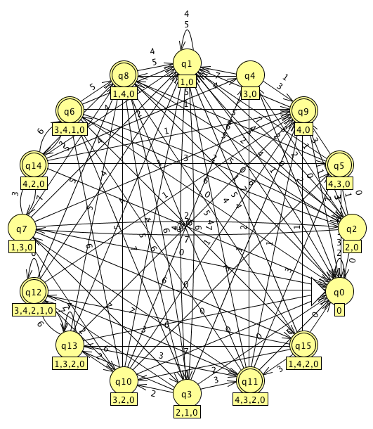
The number of deterministic states has gone up from 5 to 16. It is well known that NFA to DFA conversion can potentially result in a serious explosion of states. The worst case expansion is one where n states of an NFA result in 2**n states in the corresponding DFA.
Intermediate Conclusion
We have a conceptual solution! With a bit of graph manipulation we can convert temporal sequences into a regular deterministic FSM that can be synthesized to any kind of logic that we want.
Not only SMT2, but even gates: for problems that are currently intractable with formal verification (because it might take way too long to prove), we could synthesize the design and the assertions to an FPGA and continuously monitor whether or not the assertions are true at all times, even after days of running.
There is no partical implementation, of course, but that’s a matter of somebody just doing the work.
The question is how?
There are multiple ways about this.
For RTL construction kits like SpinalHDL or MiGen, one could develop a framework similar but not identical
to SystemVerilog, that can be used to create sequences and other features.
Once in place, those sequences could immediately be converted into an FSM, be made deterministic, and output as Verilog
with the boolean-only assert, assume and cover statements that are currently already supported
by SymbiYosys and SpinalHDL.
For Verilog, one would have to expand the current Verilog parser to support the SystemVerilog syntax. And then, in Yosys, implement all the FSM handling.
Or would you?
Actually, no! The second part of the work, implement all the FSM handling, has already been done!
Advanced Formal Support in Yosys Already Exists
Until now, I’ve mentioned “open source” formal verification support in Yosys. What I forgot to say was that Yosys already supports a closed source SystemVerilog parser and elaboration library from a company called Verific.
You need to pay for a license for this library (price unknown, but probably not cheap), but the Yosys code that uses the library is just as free and open source as all the rest. Symbiotic EDA has already communicatd their intention to release a commercial, binary-only version of Yosys that includes the Verific frontend.
And, indeed, it’s just another Yosys frontend that is open source as well.
The code is split into just 2 main files.
verific.cc is the main driver that converts an elaborated SystemVerilog design into RTLIL just like all the other frontends. It’s a lot of code, but it’s not particularly complex.
verificsva.cc
handles everything that’s specific to SystemVerilog assertions. It contains exactly
what, by now, you’d expect it to contain: it will build one grand
non-deterministic FSM out of sequences. It will convert that FSM into a deterministic version.
And it will connect the match signal, now a boolean equation that is an output of the FSM, to
an $assert, $assume or $cover cell in the RTLIL representation just like it did with
pure boolean equations for the Verilog frontend.
In the previous section I mentioned that we have a conceptual solution but no practical implementation. Here we have a full practical implementation, and it’s quite a bit more complex than our conceptual example.
A good example is how the Verific frontend has 2 types of transitions to step from one state to the next: ‘edges’ are only taken one a clock edge, just like we expect from a traditional FSM, but ‘links’ are transitions when a combinatorial equation evaluates to true. As a result, the initial FSM can travel through many states in one clock cycle.
This kind of representation make it possible to implement SystemVerilog sequences in an easier way, but it requires an additional intermediate step that normalizes the NFA-with-links-and-edges to an NFA-with-edges-only, before the latter is then fed into the NFA to DFA algorithm.
Here’s a very non-exhaustive list with a bunch of interesting sections of the code that might help aspiring codes with understand what’s happening (a process that’s still ongoing for me!)
-
The main entry point that starts the processing of a SystemVerilog sequence.
It distinguishes between regular boolean equation assertion processing (similar to the open source Verilog Yosys frontend) and the advanced temporal properties.
-
This is the most interesting part, where various SVA sequence operators are converted into FSM states.
For example, the code here handles the regular
a ##[2:3] btype sequence concatenation operator.You can see here how it simply adds an additional FSM node and edge transition for the minimum request number of wait cycles, which is then followed by code that deals with the optional additional wait cycles: more FSM nodes are, but instead of just an edge between them, the code adds an edge and a link. In other words: those FSM nodes can be skipped or not, a perfect example of a non-deterministic FSM.
-
Converts the NFA with edges and links to an NFA with just links
-
Converts the NFA to a DFA.
If one were to implement an open source Verilog parser that supports sequences, one would ‘only’ have to implement the parser and AST construction code. The whole FSM handling can be a relatively straightforward adaptation of the code here.
Similarly, adding sequences to SpinalHDL or MiGen would require a port of the FSM handling code to Scala or Python.
Call to Action
Almost all components to create a kick-ass open source formal verification tool are there. All that’s missing are a few piece to make everything come together.
Adding complete SystemVerilog support to the existing open source Verilog parser is a huge task
but it’s not necessary to immediately support all SystemVerilog features (even the Verific frontend
still have a number of missing pieces). Just like Verilog parser has seen gradually addition of
regular SystemVerilog features (logic, interface, and, yes, assert, cover and assume)
sequence support could be added in stages as well.
Support for SpinalHDL, MiGen and other Verilog generating frameworks could be added as well.
They would require a rewrite of the FSM handling code of verificsva.cc, but it’s not
overly complex.
The possibilities are very exciting. I want to be able to contribute to this area in the future and hope that others want to do so as well.