Pano Logic JTAG First Contact
- Get a Xilinx-compatible JTAG Programmer
- Find the JTAG Connector on your G1 or G2
- JTAG Pin Order and JTAG Adapter
- G2 JTAG Adapter
- G2 LX150 JTAG First Contact
Steps required to get JTAG working on a Pano Logic thin client.
Get a Xilinx-compatible JTAG Programmer
I bought mine on Amazon. It’s a obviously a clone, but still quite expensive at $35. I’ve seen similar one on AliExpress for as low as $22 + shipping, but I wanted mine fast.
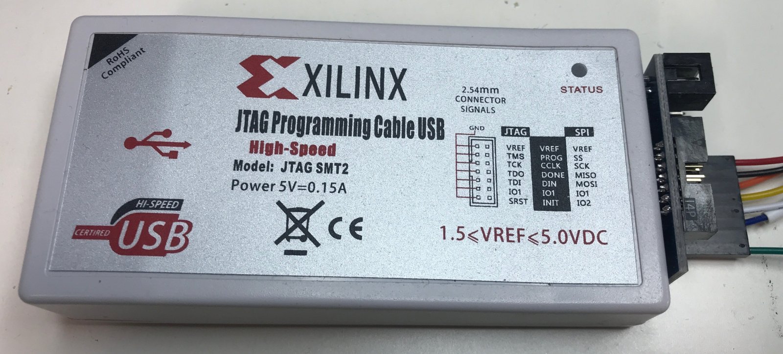
This JTAG programmer is “USB certired”. How very reassuring!
Find the JTAG Connector on your G1 or G2
Not very complicated: I’ve done that for you in the pictures below.
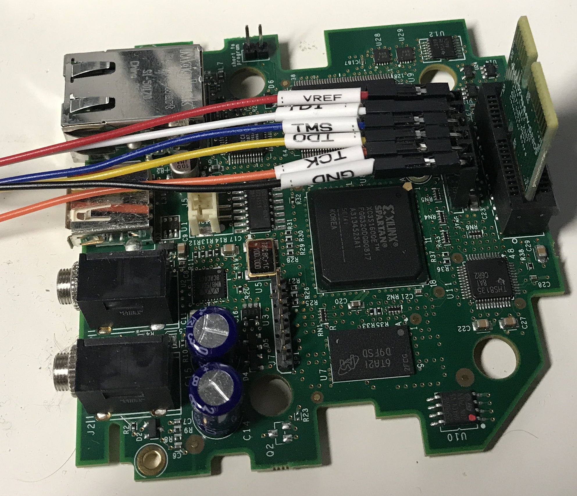
On the G1, there are 2 identical looking 6-pin connectors. The one next to the large capacitors and the audio connectors is for SPI flash programming. The JTAG connector is located right next to the board-to-board connector:
It’s easier for the G2: there is only one connector with 6 pins:
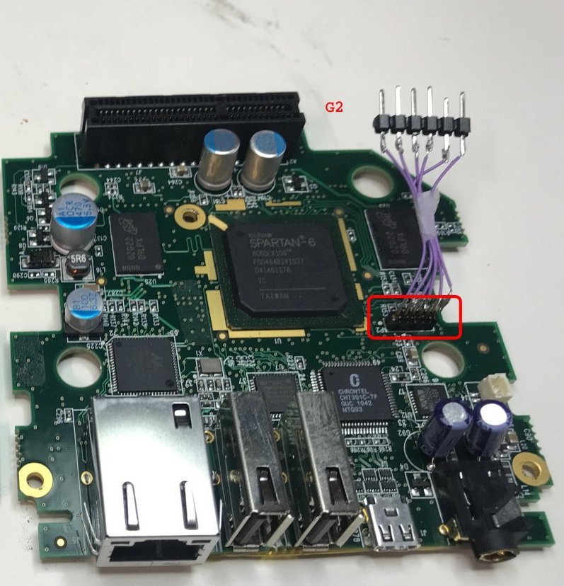
The G1 has conventional-sized connector pins. The G2 has really tiny ones.
JTAG Pin Order and JTAG Adapter
The order of the pins doesn’t seem to follow some Xilinx standard order, but it is the same for the G1 and G2.
- VREF
- TDI
- TMS
- TDO
- TCK
- GND
For the G1, the GND pin is located closest to the FPGA. For the G2, it’s the opposite: the GND pin is on the farthest away from the FPGA.
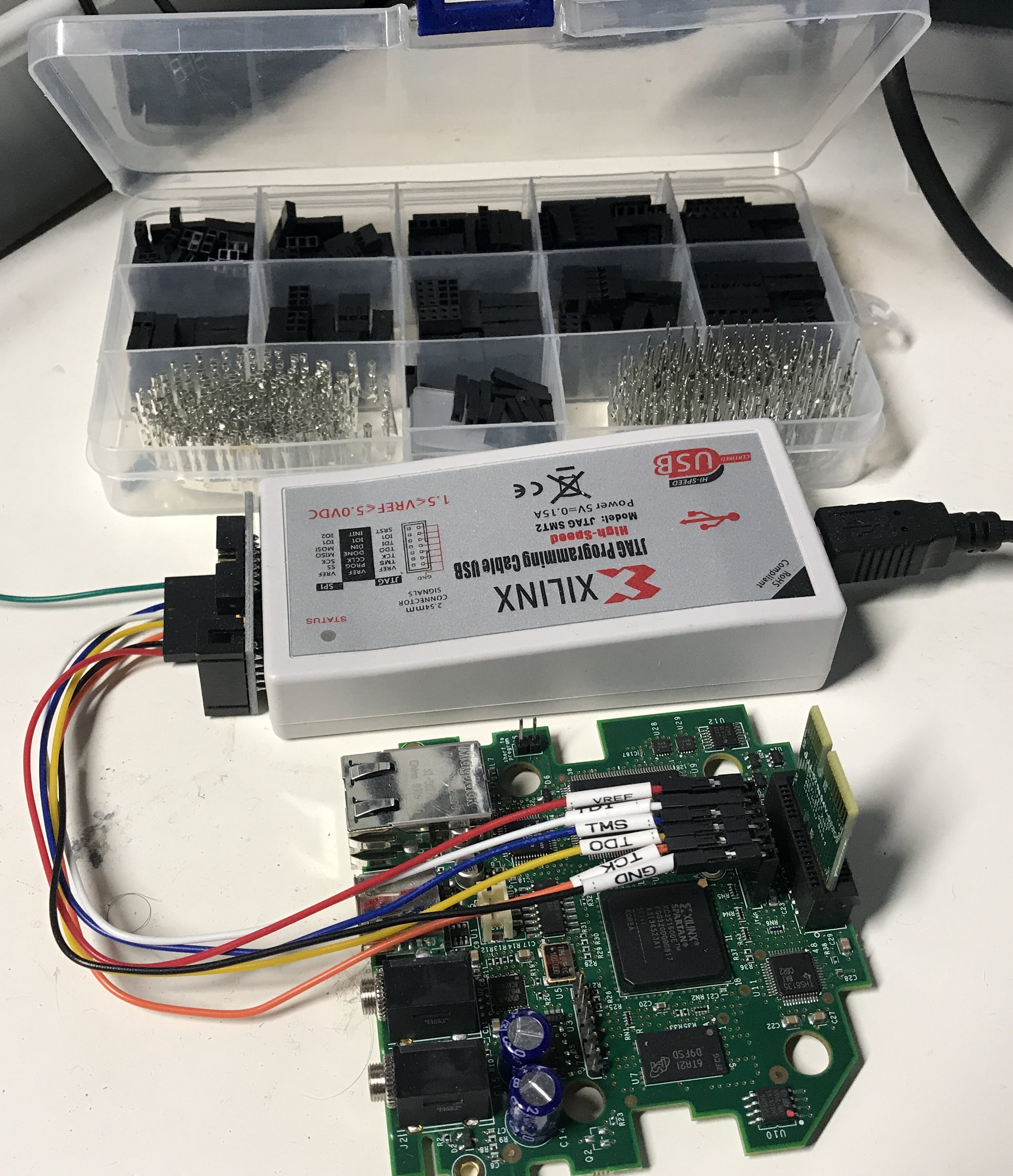
I created a litter adaptor for the G1. The JTAG programmer comes with wires that can be plugged in directly into the G1 pins. However, to make the board work, you also need to plug in the auxiliary board, which is located right above the JTAG connector. It works, but it’s a bit cramped.
To make plugging in and out easier, I created a little 90-degree adapter with a connector construction kit. It cost less than $7 on AliExpress, and I use it more than I initially expected. It’s great to create quick ad-hoc connector adapters that would otherwise require tedious checking of pinouts whenever you need to recreate a particular setup.
You can see the kit here:
G2 JTAG Adapter
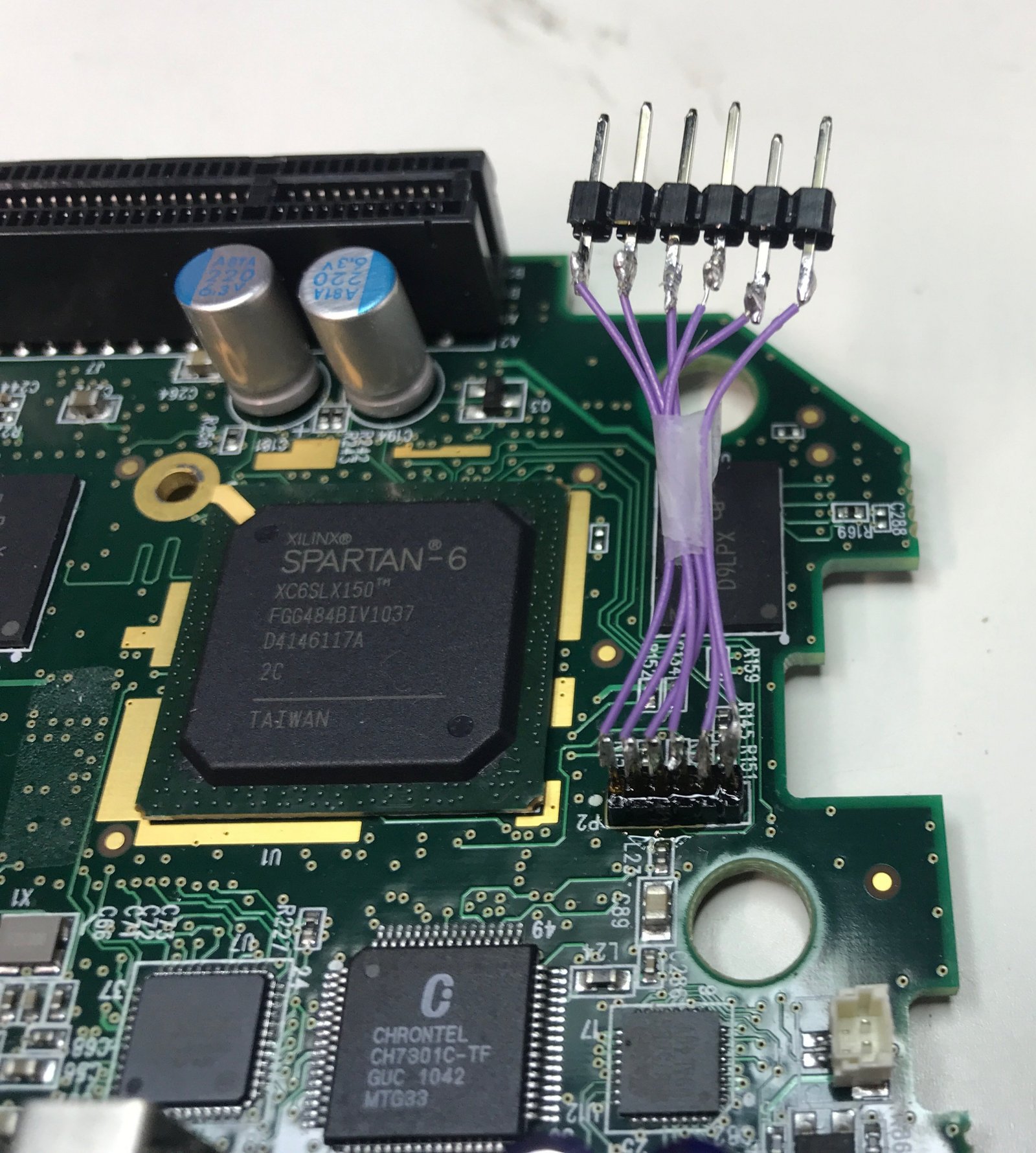
For the G2, I soldered some wire-wrap wires between the tiny on-board connector and a strip of standard pins. Wire-wrap wires are great for this kind of stuff: they’re super thin and very easy to solder. I’ve even used them to solder wires to individual TQFP144 pins.
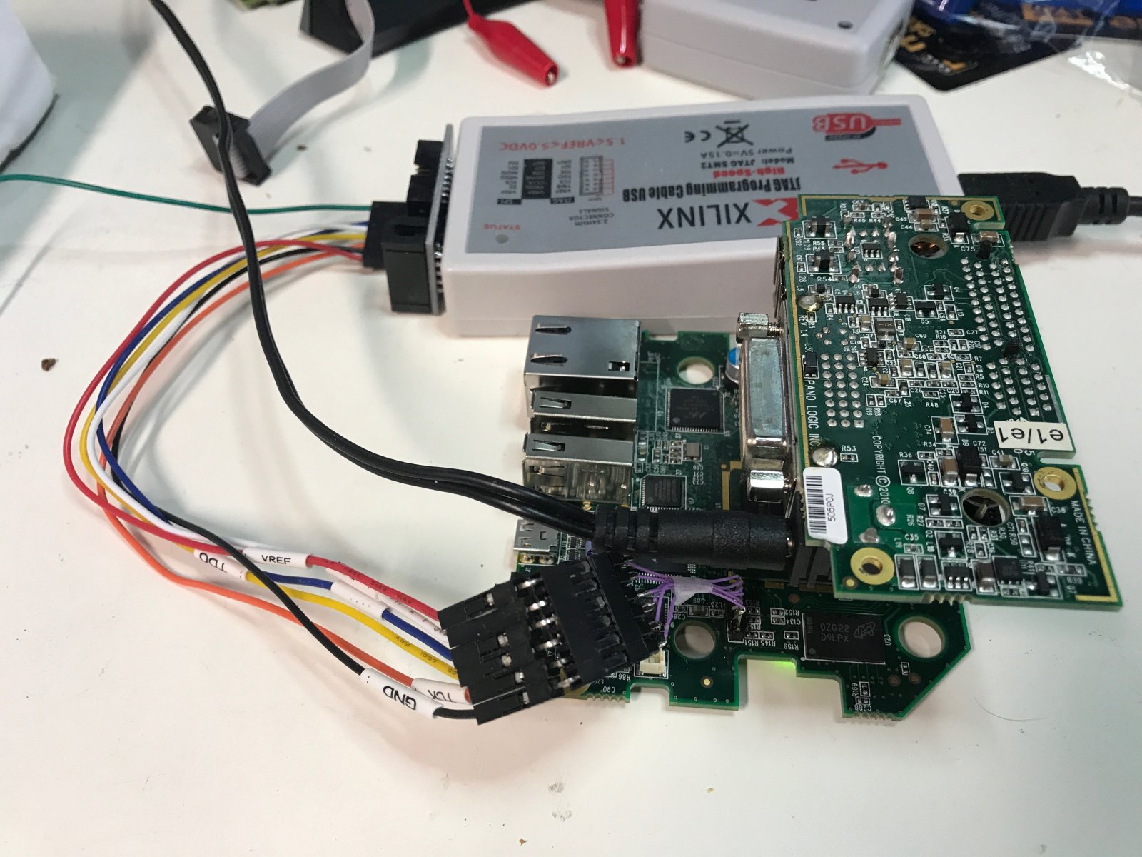
Since the pin ordering is the same for the G1 and G2, I can now simply plug in my G1 JTAG adapter:
G2 LX150 JTAG First Contact
The free Xilinx ISE 14.7 doesn’t support the Spartan-6 LX150 for synthesis and place-and-route (you need the Win10 version for that), but it does support the LX150 in the Xilinx iMPACT JTAG control software.
After connecting the JTAG Programmer to the G2, and doing a boundary scan test, you should see the following:
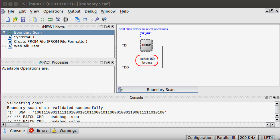
“Boundary-scan chain validated successfully” and LX150 device detected!