Tektronix TDS3000(B) Screen Repair
- A TDS3052 with a Broken-Not-Broken LCD Panel
- A TDS3014B with Very Broken Screen
- Opening the Scope
- Power Supply Assembly Removal
- Removing the Motherboard
- Taking Out the LCD Panel
- Replacing the Protective Screen
- Replace the LCD Panel
- The Result
- Footnotes
A TDS3052 with a Broken-Not-Broken LCD Panel
Last summer, Joshua tricked me into bidding $165 for a TDS3052 oscilloscope. The photos on the surplus auction site showed major screen corruption but I only noticed that after placing my bid. That must be why I “won” the auction without anyone else going higher.
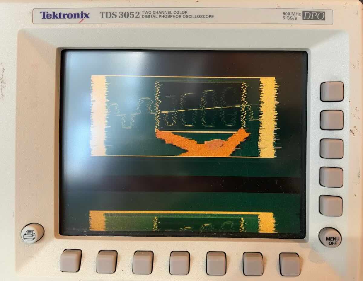
At home, the screen was perfectly fine initially, but after a while the corruption would appear. Maybe something temperature related? This smelled like a capacitor issue, so no worries, I’ve been down that road before with a TDS220.
I took the scope apart, extracted the LCD, and found nothing to repair: unlike the TDS220, most capacitors in the LCD panel are buried underneath some very fragile flex cables. Here’s that panel after removal of the polarizer:
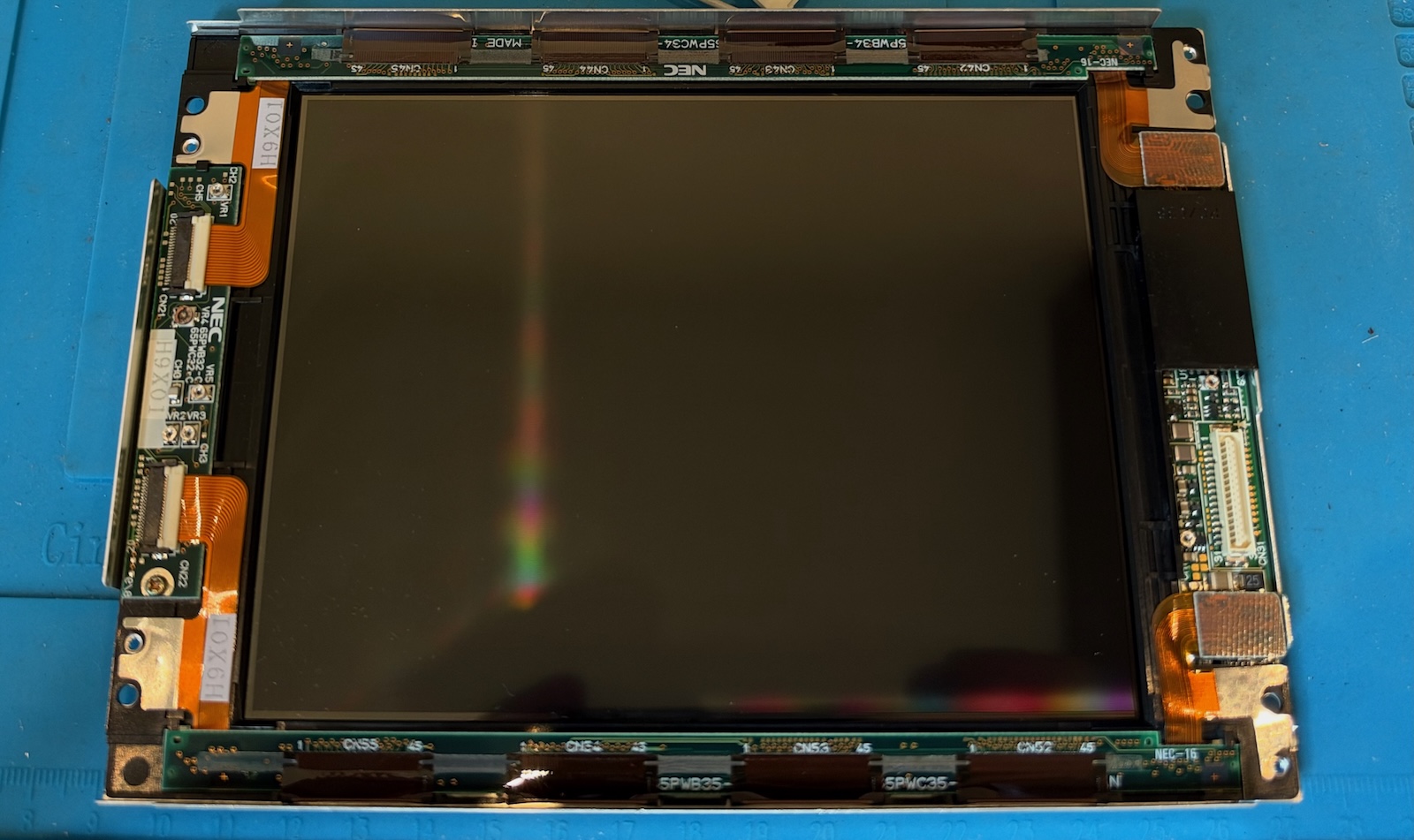
There’s a dilemma here: you could say “the screen is broken anyway, what’s there to lose?”, but while it clearly had issues, the scope was still usable for about an hour before it became a problem. In the end, I decided to make do with what I had and ordered a replacement LCD panel on eBay. The TDS3000(B) series uses a 65BLM-3 panel. You’ll find many for $150, but one vendor has them for $67, make that $90 after shipping, taxes and tariffs.
The next day, I reassembled the scope and… it just worked. No issues whatsoever. The screen has been rock solid ever since. Maybe the video signal cable had some oxidation that was removed by reseating the cable?
I now had a fine oscilloscope with a spare LCD panel on the way.
A TDS3014B with Very Broken Screen
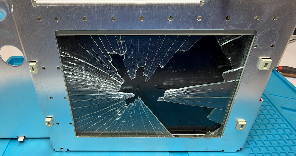
Meanwhile, I had a project going on for this scope and its younger sibling from the TDS3000B series. I needed a B-version for testing but didn’t want to pay the price of a working one. As luck would have it, this TDS3014B with broken LCD panel and shattered protective screen showed up on eBay for $180:
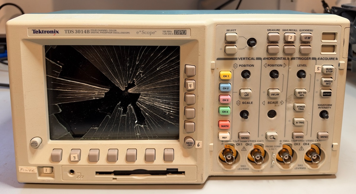
Perfect!
It also came with a TDS3GV GPIB/RS-232/VGA communications card. These go for at least $135, so I was looking at a steal. It’s lacking a few knobs which is a problem for a scope that’s destined to become one of my daily drivers, but I can just move some from the TDS3052 which only has 2 channels and will only be used for testing.
With the communications card, I could set up a remote control session over RS-232, make Ethernet work, and dump a screenshot. Other than the screen, the scope appeared to be fully functional.
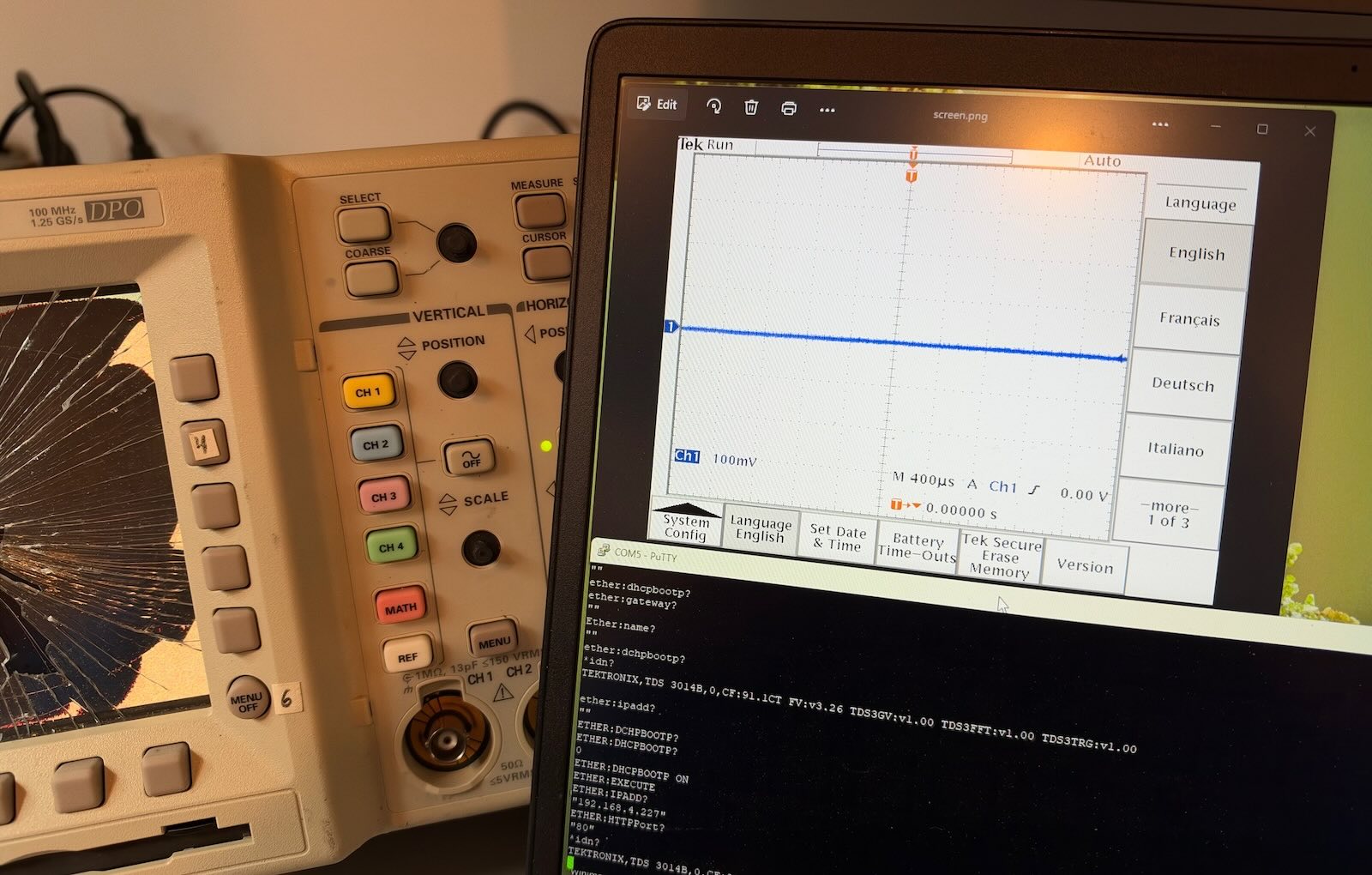
All that was left was fixing the screen.
The remainder of this blog post is essentially just disassembly instructions. These scopes were very popular and still are with hobbyists. You can find plenty of videos about them on YouTube, you can even find some on how to replace the CCFL backlight, but that one doesn’t show how to get the LCD panel out.
The instructions below apply for both TDS3000 and TDS3000B versions.
You’ll need a Torx-15 to free the motherboard and a Torx-10 to get at the LCD panel.
Some disclaimers: Unplug the AC power cable before doing any work on the scope. Even after unplugging, deadly high voltages may be present for an extended period of time. Some of the components in the scope are fragile. It’s easy to damage them if you don’t know what you’re doing!
Opening the Scope
TDS3000 scopes have a peculiar way of opening the case. There’s really no point in taking pictures of it, this video shows how it’s done:
How to Open a Tektronix TDS3000 Series DPO Oscillscope
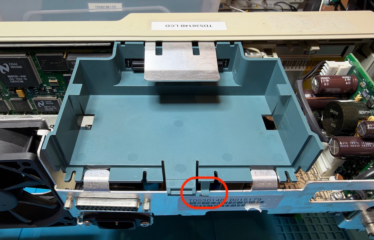
Once open, remove the expansion card tray by pulling back the metal a little bit around the plastic pin, then slide the tray out.
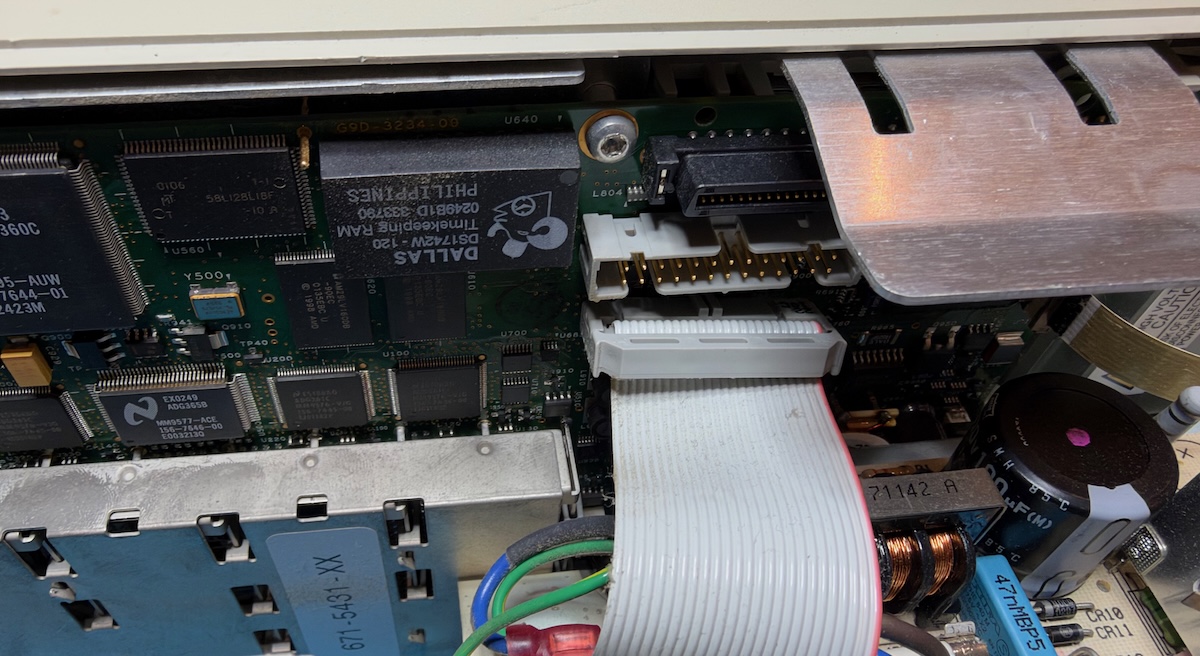
Since you’re looking at it anyway, you might as well unplug the parallel port cable:
Power Supply Assembly Removal
The power supply assembly sits on top of the main assembly like a bridge.
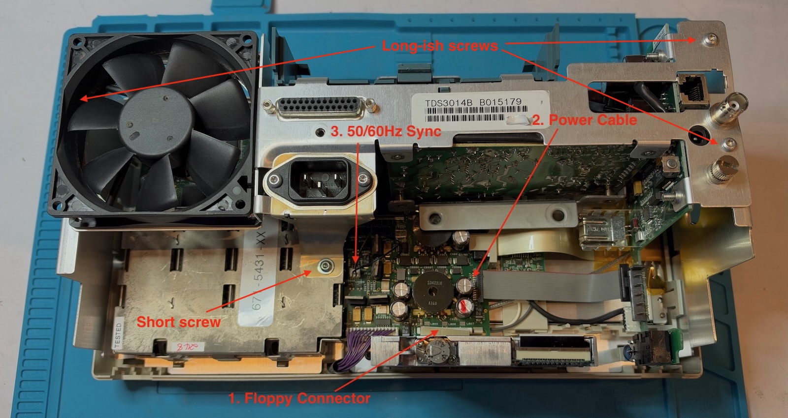 (Click to enlarge)
- Disconnect the floppy drive flat cable and take the drive out.
-
Unplug the gray flat cable that supplies power to the motherboard.
It’s surprising how thin that cable is…
-
Unplug the 50/60 Hz main sync trigger cable
This one is a pain: it doesn’t come loose easily and there’s always the possibility that you rip the wires out.
- There are 3 long-ish screws, 2 on the right and 1 on the left, and 1 shorter screw below the power plug. Remove them.
A backlight power cable hides underneath the motherboard power cable. Unplug that one too:
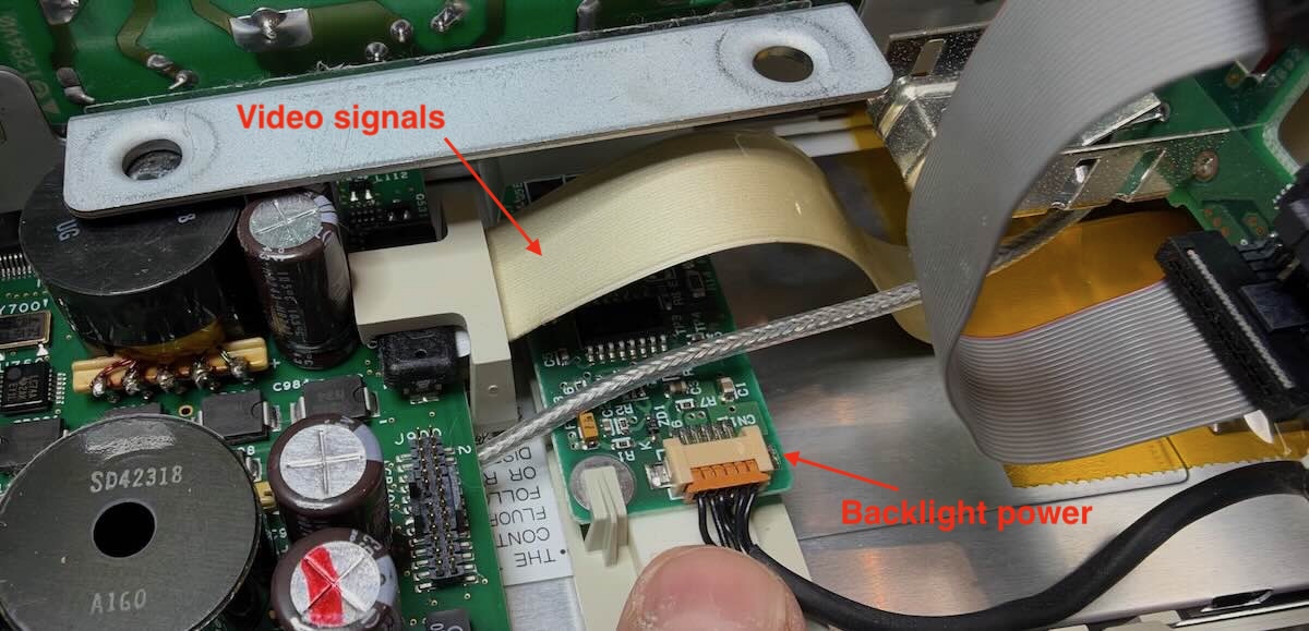
On my TDS3014B, but not on the TDS3052, there’s a retaining clip for the LCD video signal cable. If you have that clip, remove it later when the motherboard is loose.
The TDS3000B series has a built-in Ethernet connector on one of the power supply boards. It is connected to the motherboard with a flat cable located right next to the CPU. Remove that too:
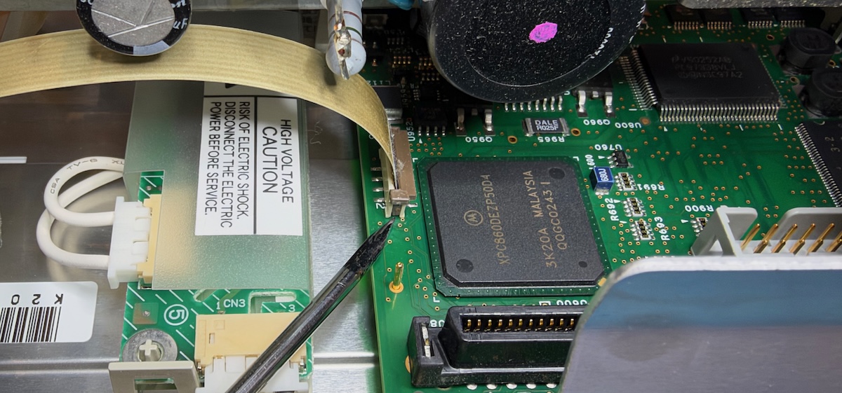
Lifting the cable locking mechanism is a bit finicky, having the power supply assembly unscrewed really helps here.
If you have a 4-channel version, the only thing left connecting the power supply to the rest of the scope is a coax cable that goes to an external trigger BNC connector in the back. You do NOT need to remove the BNC connector: the coax cable can simply be pulled out:
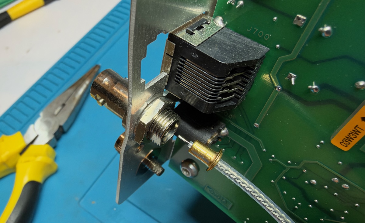
The power supply assembly is now completely disconnected.
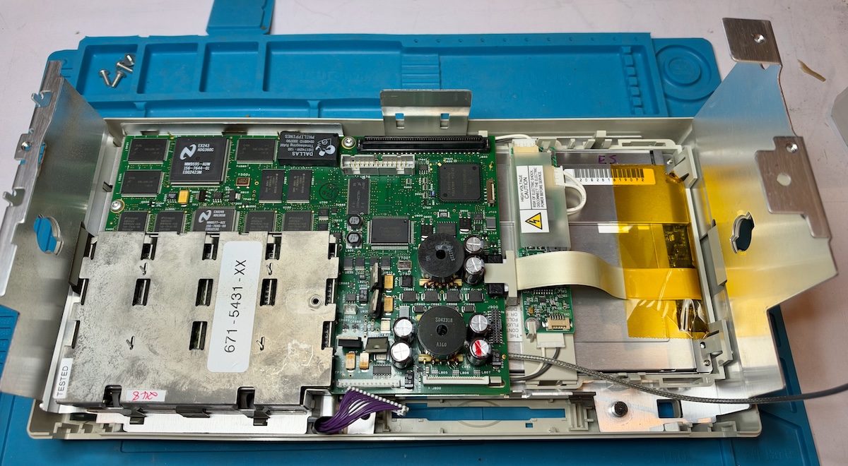
Many people fix their broken TDS3000 scope by drilling out the battery out of the Dallas DS-1742W non-volatile SRAM/real-time clock and soldering a CR2032 battery holder on top of it. You can do this without desoldering the DS-1742W, but I wouldn’t recommend it: the vibrations of the Dremel tool can damage the motherboard PCB. This video does it right. It also shows pretty well how to do the disassembly up to and including removing the motherboard.
Removing the Motherboard
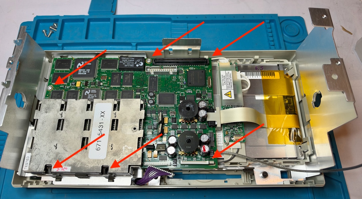
To remove the motherboard from the front assembly, you need to remove or disconnect:
- 2 plastic clips
- 4 screws
- the front panel connector
- the video signal connector, if you haven’t already
The front panel cable comes off easily:
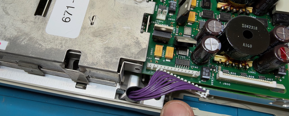
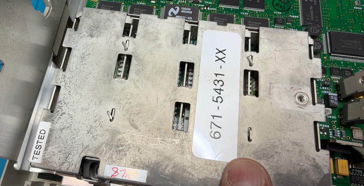
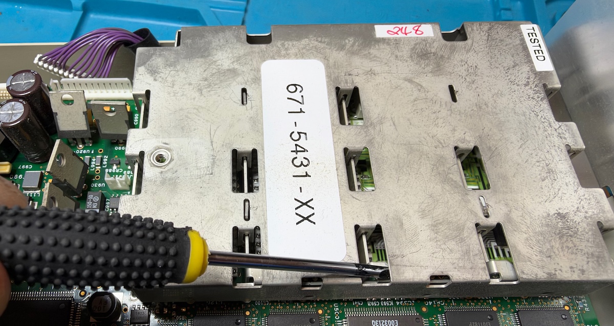
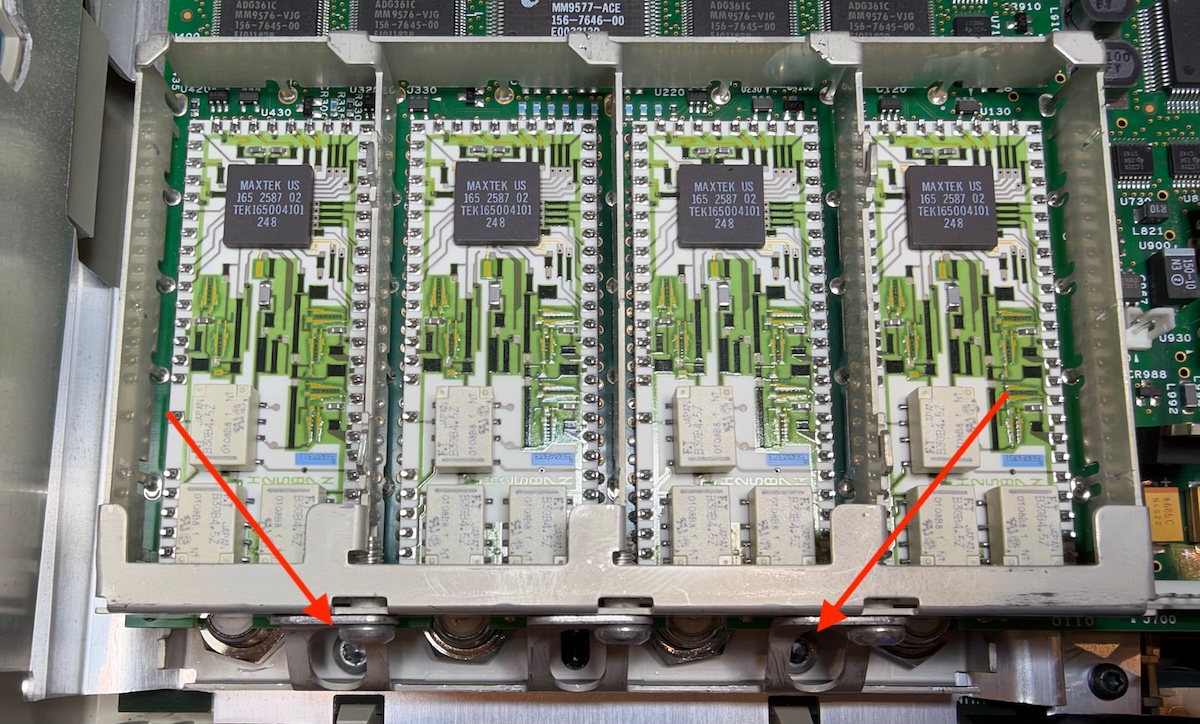
2 of the 4 screws are freely accessible; the 2 others are hidden by the analog acquisition enclosure. They are accessible and can be removed without taking off the EMI enclosure, but since I found it easier to reassemble the scope with the enclosure removed, I already remove it during disassembly.
Use needle-nose pliers to align the metal thingies that lock the enclosure in place:
To lift the enclosure from its sleeve, I insert a flathead screwdriver in one of the openings and rotate it:
The 2 hidden screws are here:
Unlock the 2 clips, unscrew the 4 screws and you can lift the motherboard:
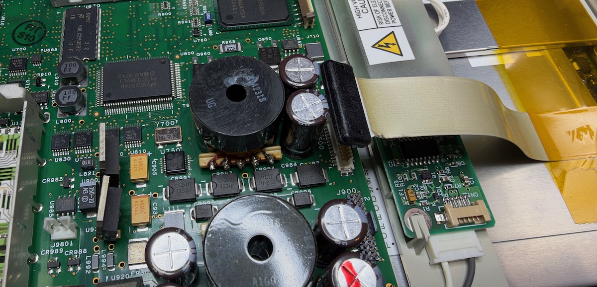
Lift the top of the annoying video signal cable clip first, then you can remove the cable itself:
Taking Out the LCD Panel
You might think that you now have full access to the LCD panel but you don’t. The CCFL backlight high-voltage power supply is wedged on top of the panel and blocks its removal. You have to take the scope further apart to take out this power supply.
This can be done with just 2 Torx-10 screws. There is one at the bottom:
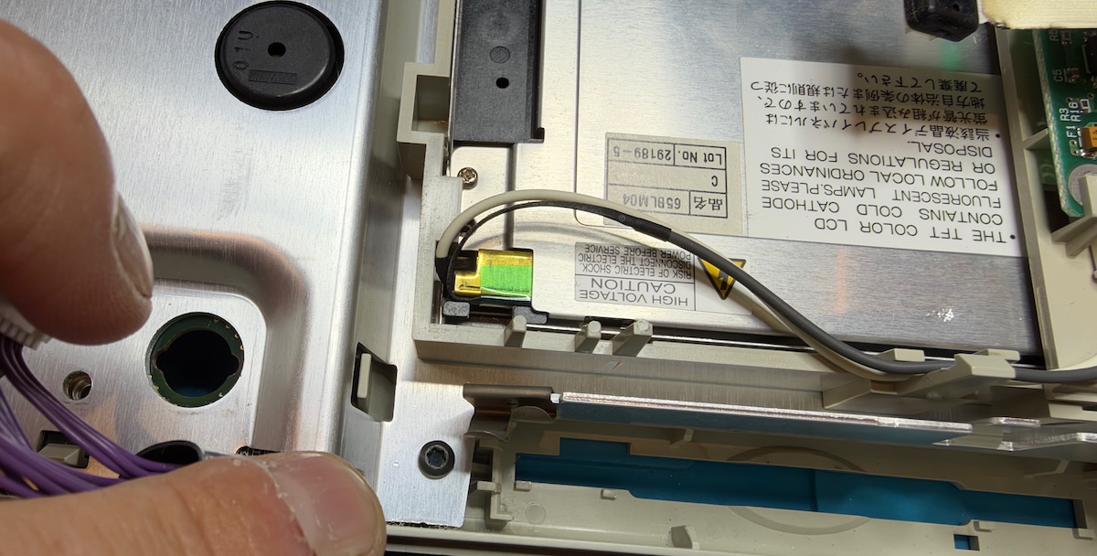
The second one is at the top. Once gone, the front panel and the screen assembly can now be separated:
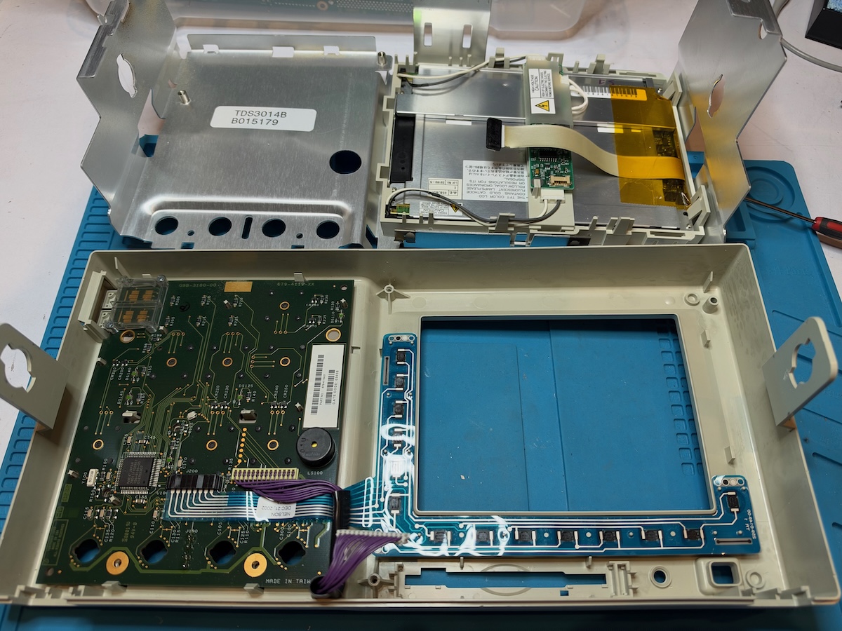
Turn around the LCD assembly and you’ll see how the LCD plastic enclosure is mounted to the sheet metal with 4 retaining clips. You can just slide it out, there are no screws:
Disconnect two LCD power plugs:
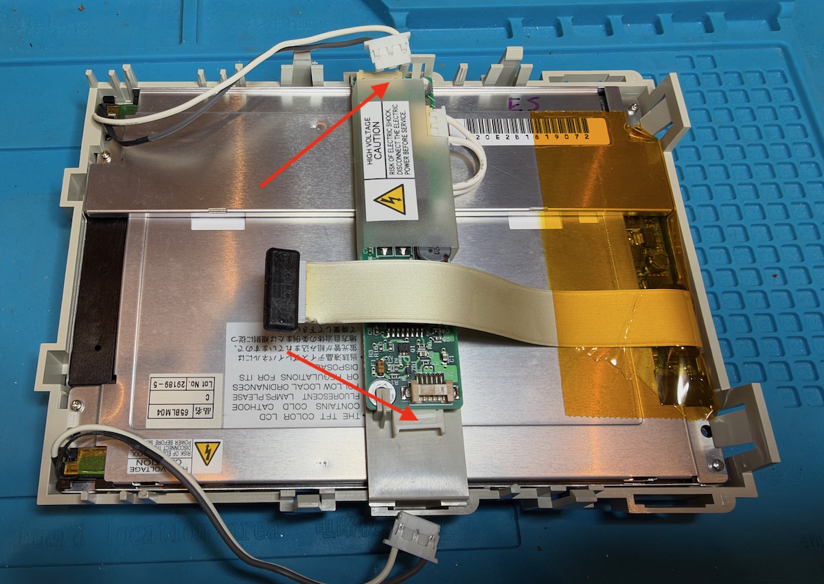
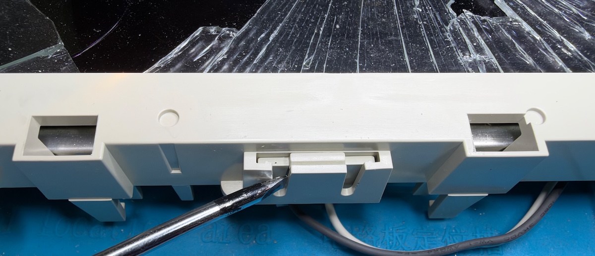
The LCD HV power supply is kept in place with 2 clips on the other side of the plastic enclosure. Use a screwdriver to unlock:
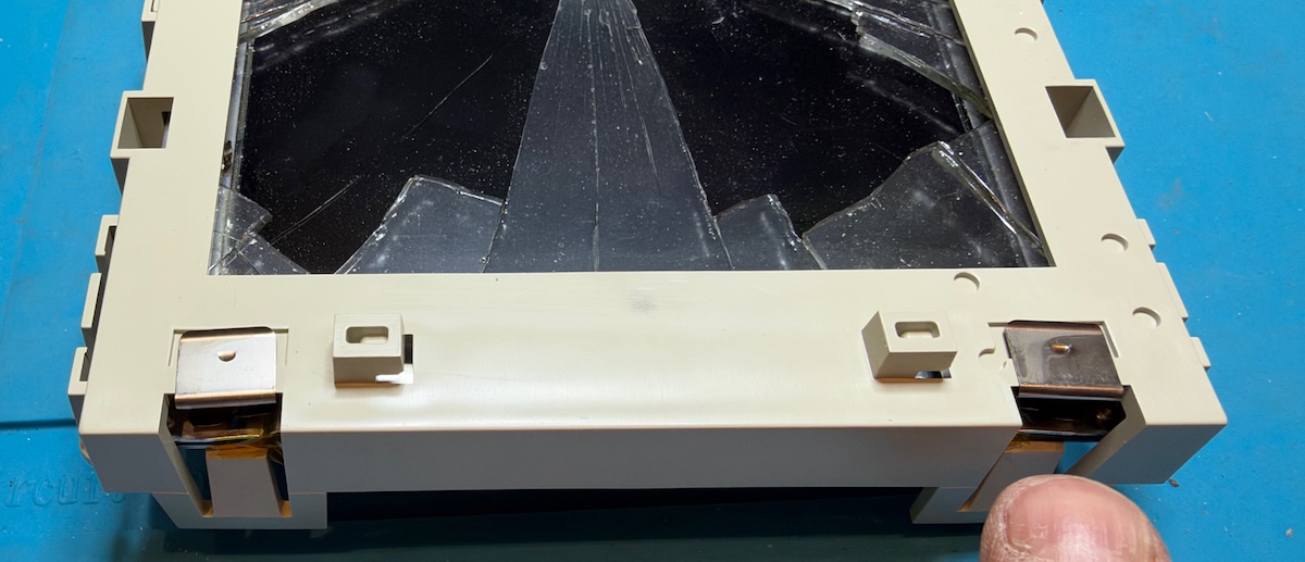
Remove 4 LCD panel springs:
You can now remove the panel from the plastic enclosure. Press the 2 plastic clips to lift the panel on the right side. Once that’s done, you can slide the panel out of the left holding tabs:
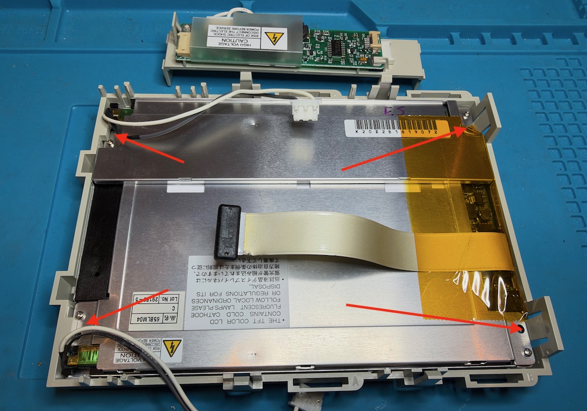
The panel is loose. Phew!
Replacing the Protective Screen
On my unit, the protective screen tried in vain to protect the LCD panel from getting damaged. I don’t know which material was used for the screen; the shards don’t seem to be sharp enough to be glass.
The dimensions of the original screen are 151 mm x 118 mm and is 1.8 mm thick.
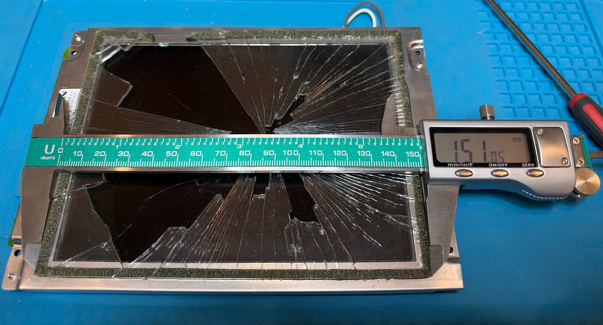
There is an adhesive strip around the screen that sits between the LCD panel itself and the protective screen. You need to preserve this, so carefully remove the shattered screen and peel off the strip.
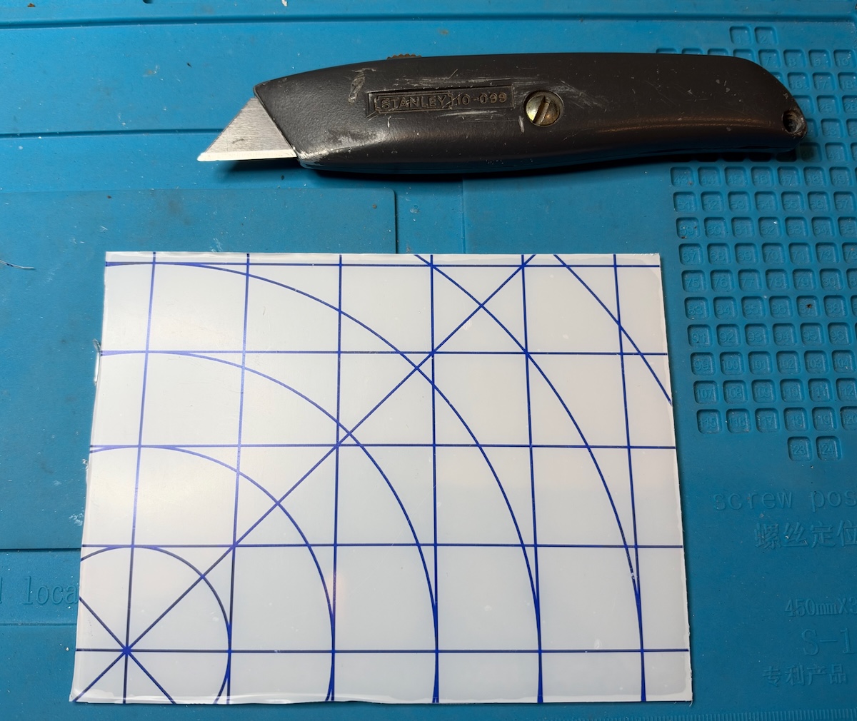
I replaced it with a regular polycarbonate 1/16” thick clear plastic sheet1, $7 on Amazon, reduced to size by scoring it many times with a box cutter, and breaking it off over the edge of my workbench. A bit like this video, but with edges that were not as tidy: acrylic sheets are easier to cut than polycarbonate2.
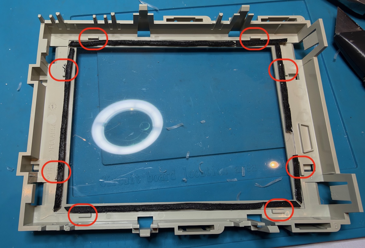
You don’t need high precision cuts, but you need to make sure that the screen fits inside the recessed rectangle of the plastic enclosure and the 8 tabs around it. If it doesn’t, use the box cutter to shave off some material from the edges until it does, then apply the recovered adhesive strips. Don’t worry if there are gaps, you won’t see them once everything is back together: everything is hidden in the bezel.
Replace the LCD Panel
The only thing left to do before assembling everything back together is recovering the video cable from the old panel and installing it on the new one:
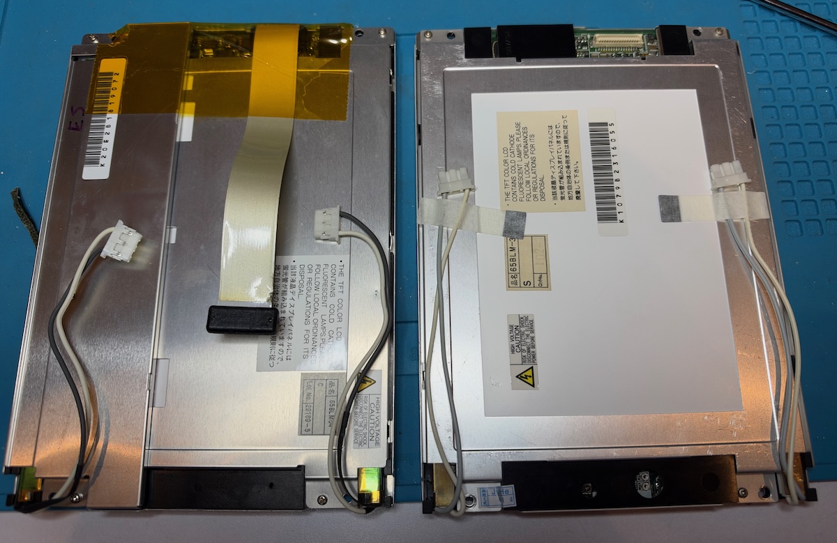
For reassembly, just do all the steps in reverse…
The Result
The new panel looks great and is much brighter than my TDS3052 with a power-on time of 47,000 hours: CCFL backlights get dimmer over time. The polycarbonate screen also works well. I don’t think it’s as scratch resistant as the original, and there might be a bit more glare, but a bright panel behind it goes a very long way in hiding imperfections, should they materialize.
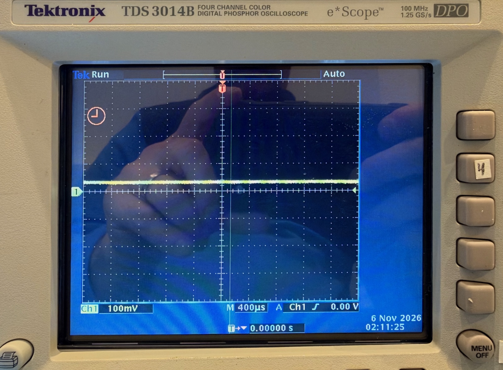
Unfortunately, the panel has a defect: one column near the center is stuck at green all the way across. While the vertical line is visible and a bit detracting if you’re a perfectionist, it doesn’t prevent normal usage of the scope. I reached out to the seller; they’ve promised to send a replacement.
Footnotes
-
1/16” is 0.2mm thinner than 1.8mm, but it doesn’t matter in practice. ↩
-
When I bought it, I thought that acrylic and polycarbonate were the same type of material. They’re not. Acrylic is harder, more scratch resistant, and optically clearer.
Polycarbonate is more flexible and thus better in a rugged environment, but it scratches more easily. I’ll just have to see how it goes and report back in a few years. ↩