Optical S/PDIF Output PMOD
Introduction
Analog design isn’t my strength, so when I do audio experiments with an FPGA, I prefer to send out the audio signal in digital format. One pretty common format is S/PDIF. The format supports coaxial cable and optical fiber as transport medium. I’m using optical because of the coolness factor (and because it once again doesn’t require any analog consideration.)
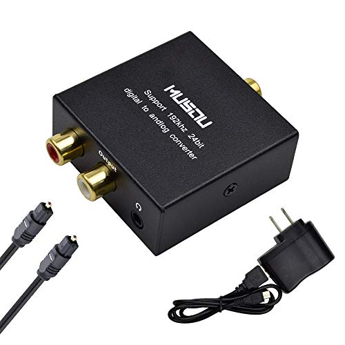
S/PDIF to analog converters can be found on Amazon for ~$12.
Optical S/PDIF works fine with pretty much any regular LED on a development board. You don’t even need a special interface: @ultraembedded showed how you can do this by holding the optical cable right above the LED!
S/PDIF is a pretty simple format and I was able to quickly reproduce that experiment:
But that’s obviously not a long term solution.
My PDM-to-PCM microphone series of blog posts has moved to the implementation stage, and that means I need something to check the results. I hadn’t designed a PCB in a while, so I sat down one evening to crank out an optical S/PDIF output PMOD.
All PCB and RTL files can be found in this GitHub repo.
S/PDIF Optical Output PMOD
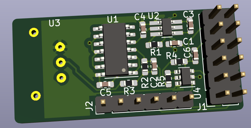
This is the result:
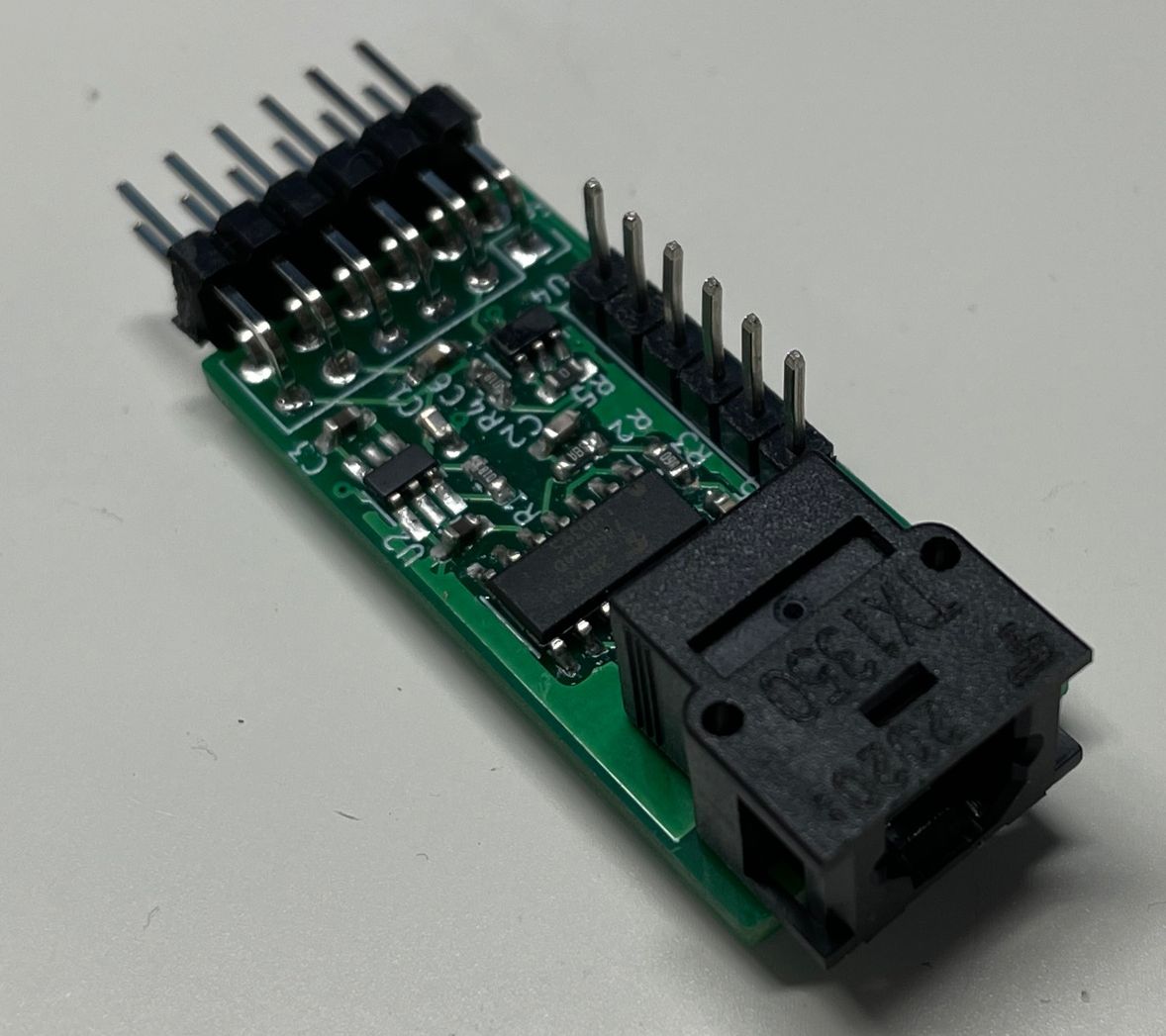
I handsoldered the 2 layer PCB and it looks terrible, but it works. Next time, I’ll just spinkle around some solder paste and use a heat gun.
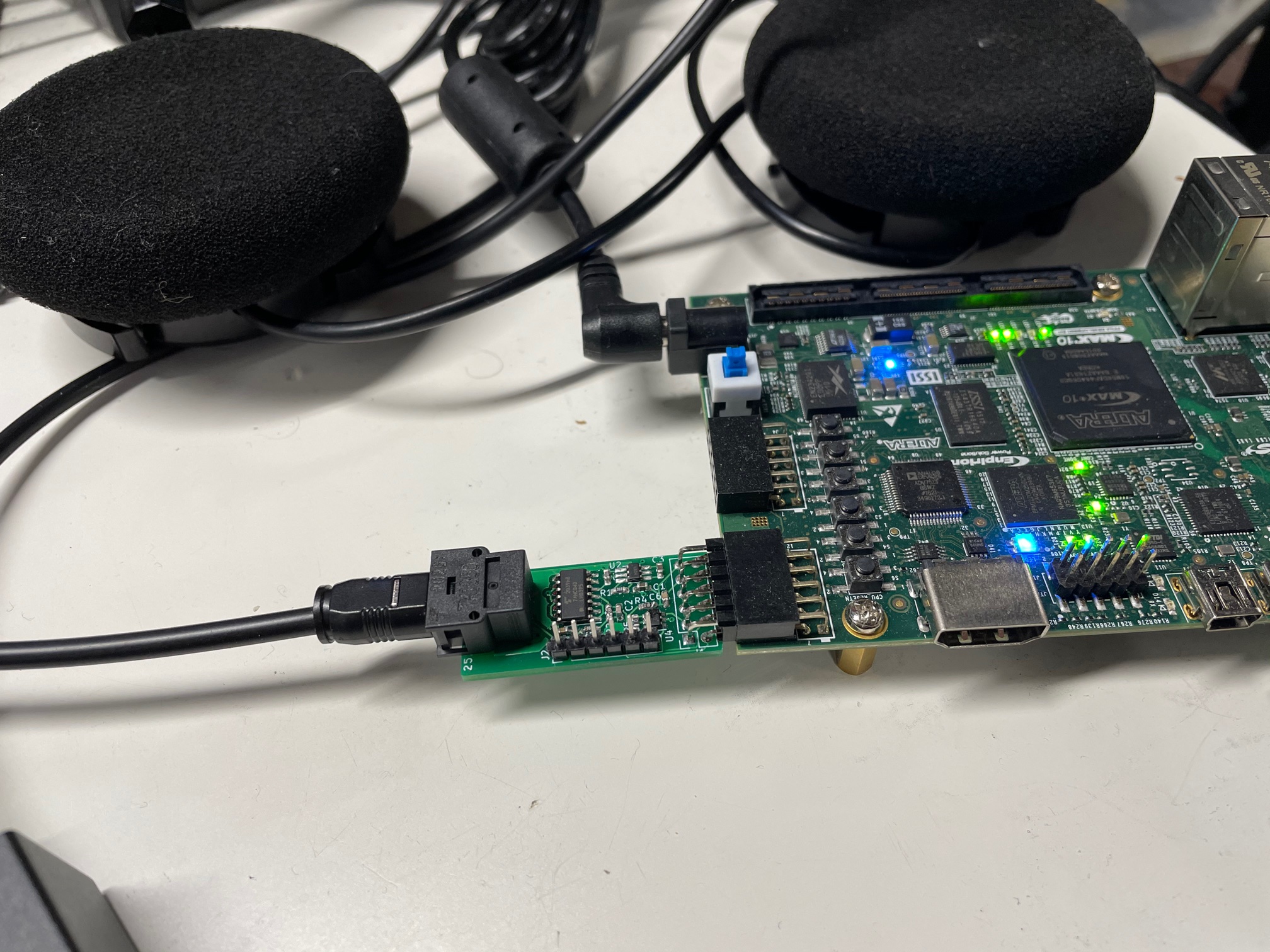
Plugging in a TOSLINK optical cable is much easier than holding it above an LED!
The PMOD has an S/PDIF optical output (TOSLINK) and 4 GPIOs. I’ve given the GPIO pins the names of an I2S interface, but since they go straight to the PMOD connector, you can use them for anything.
The total cost is around ~$30:
- PCB (JLCPCB): $2 + $14 shipping (for 5 PCBs)
- TOSLink connecter: $10
- All the rest: ~$4
SPDIF Board
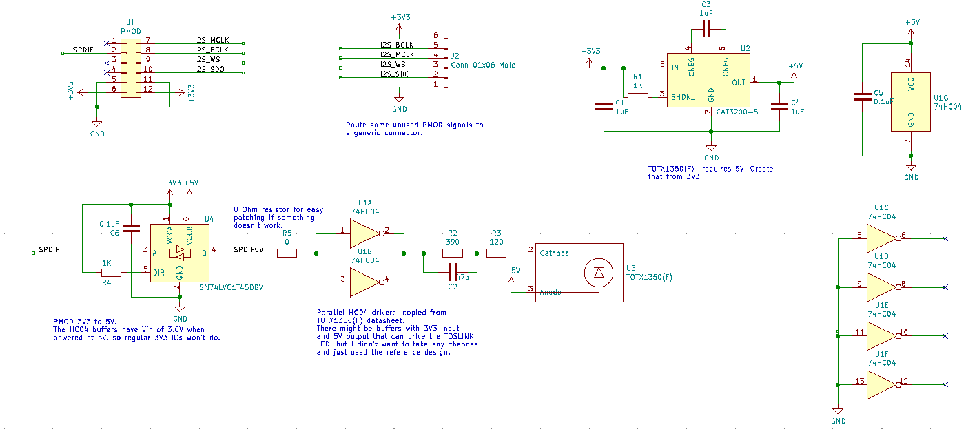
The board was designed with KiCAD.
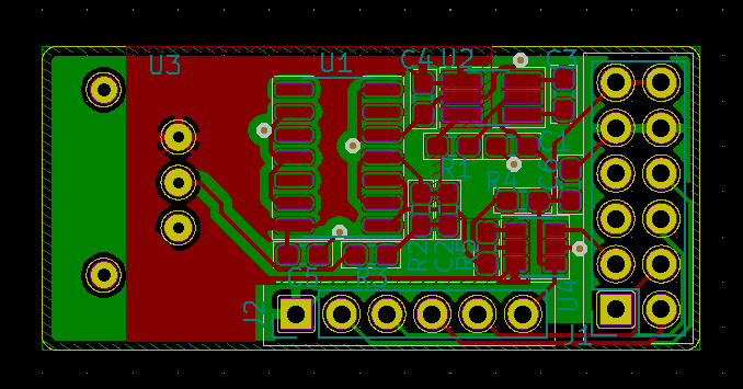
Schematic
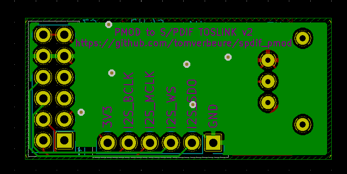
PCB
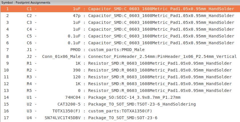
Component list
Example RTL Design
The PMOD was tested on an Intel Max10 development board, but it should be trivial to make it work on any FPGA board that has a PMOD connector.
The RTL is written in SpinalHDL, which gets converted into Verilog.
There’s also a small testbench that uses CXXRTL to simulate the whole thing. The testbench is not self-checking. You’ll need to eyeball the waveforms to verify that things are working…
The Max10 design uses a PLL to create a 6.144MHz clock out of the 50MHz oscillator clock.
If you don’t want to generate the Verilog files yourself, you can find SpdifTop.v (the Max10 FPGA
design) and SpdifOut.v (the block level module for simulation) here.
Future Improvements
I rushed this board from intial idea to to gerber-out in a couple of hours, instead of thinking things through a bit more.
Two obvious improvements come to mind:
-
Add S/PDIF input(s)
This would allow me to apply audio effects on an input source and send it back out.
-
PDM microphone input(s)
Duh.
That will be for the next iteration.