Taking Apart a Smoke Detector
- Introduction
- Disassembly
- Electronics
- Buzzer - Piezoelectric Transducer
- Conclusion
- For your Reading and Viewing Pleasure
Introduction
The smoke detector in our laundry room/cat mansion (soon to be hobby room… if the virus lockdown goes away) started to beep yesterday, even though there was no smoke to be seen. If I’m reading the manual correctly, it’s a low battery condition.
It’s one of those good-for-10-years types with non-replacable batteries. We installed it 5 years ago…
Once you switch that thing off, you can’t (and are not supposed to) switch it back on and you should throw it away.
In the middle of a shelter-in-place, you have to do something so keep yourself busy, so why not take it apart, see what’s inside, and hopefully learn something new?
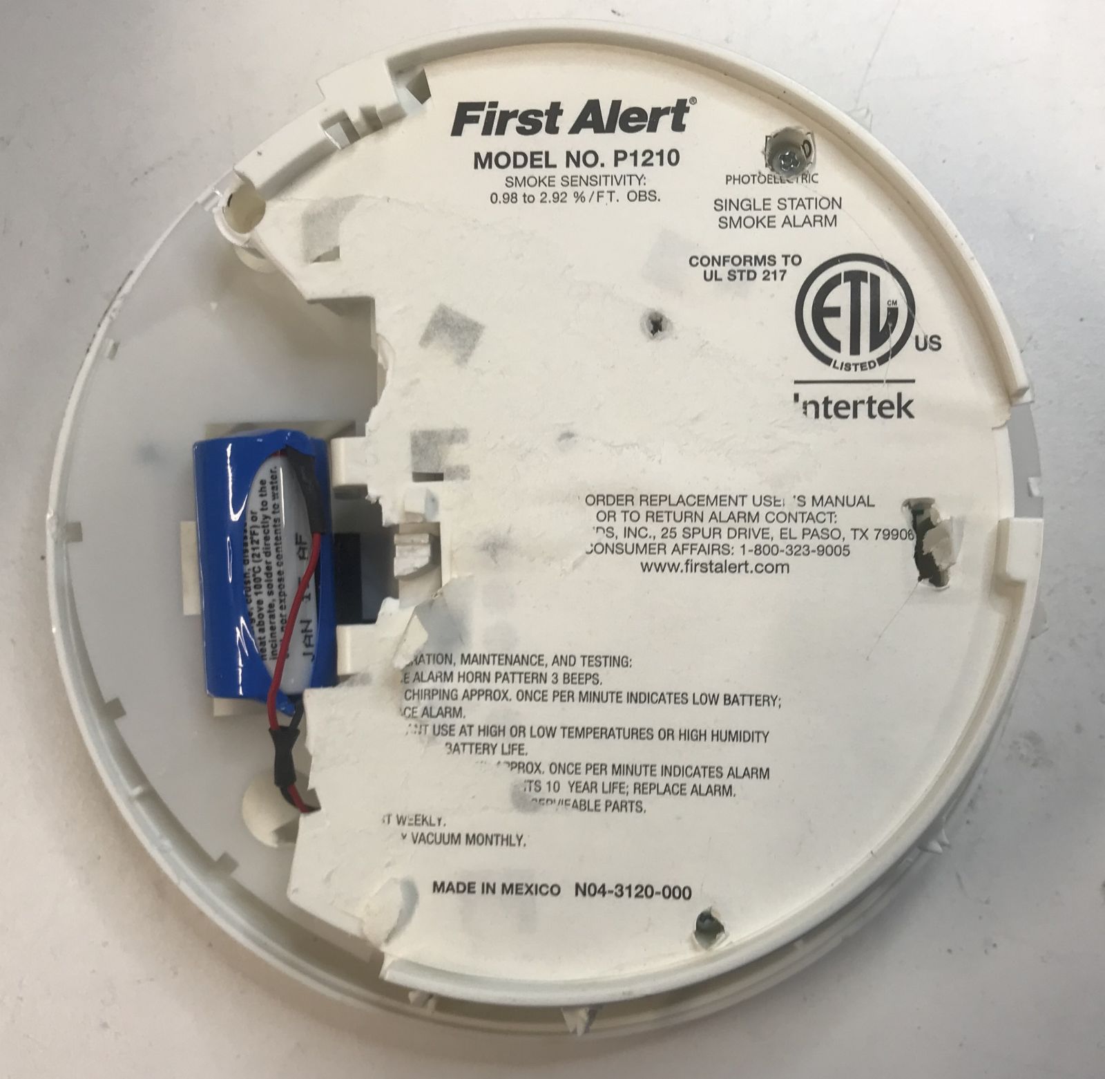
Disassembly
I didn’t take any before pictures, but there’s a bunch of plastic click mechanisms to keep things in place once it’s assembled. I used pliers to cut my way through things. Only later did I discover that there are also some screws hidding behind glued on paper that make taking it apart a little bit easier.
The first thing to appear was the battery.
Inside the plastic enclosure are 3 main components:
- PCB
- Battery
- Buzzer
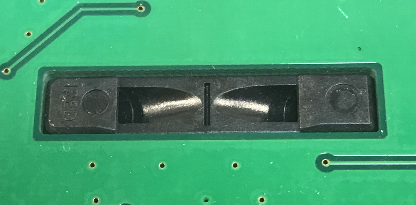
At the bottom of the PCB, you can see how the power switch, at is surrounded by 2 plastic prongs. The mechanism to permanentaly prevent switching the smoke detector back on after it has been disabled is purely mechanical. Once the plastic has been removed, you can easily switch it back on.
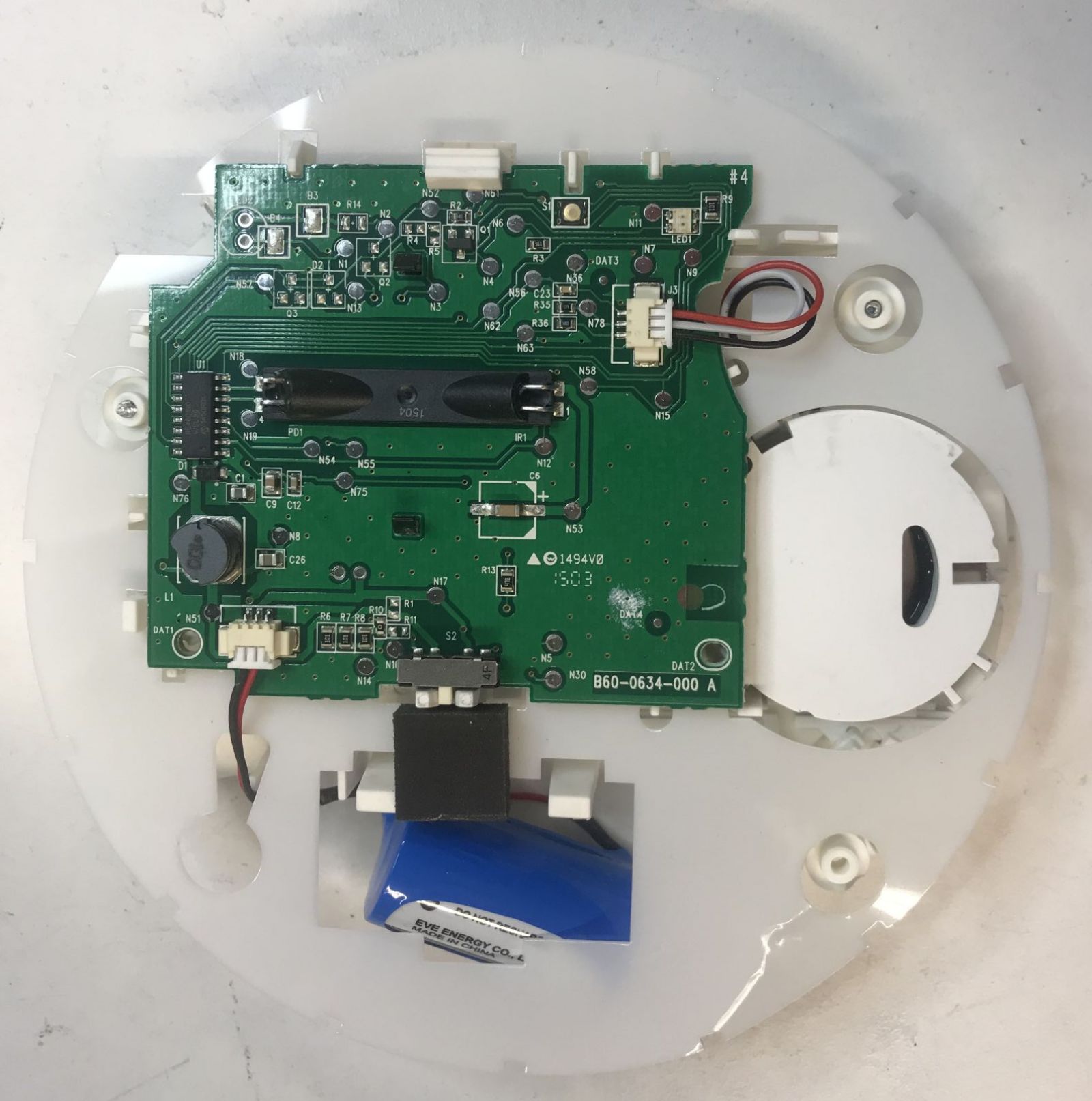
Once disassembled, it looks like this:
There are 2 main types of smoke detector: photoelectric and ionization based. There is no best type: the photoelectric ones respond faster to smoke created by smoldering fires while ionization based smoke detectors respond faster to smoke produced by fanning flames.
For best protection, the US Fire Administration recommends using both types!
In the center of my smoke detector is an integrated IR emitter and detector, so we’re dealing with a photoelectric one here.
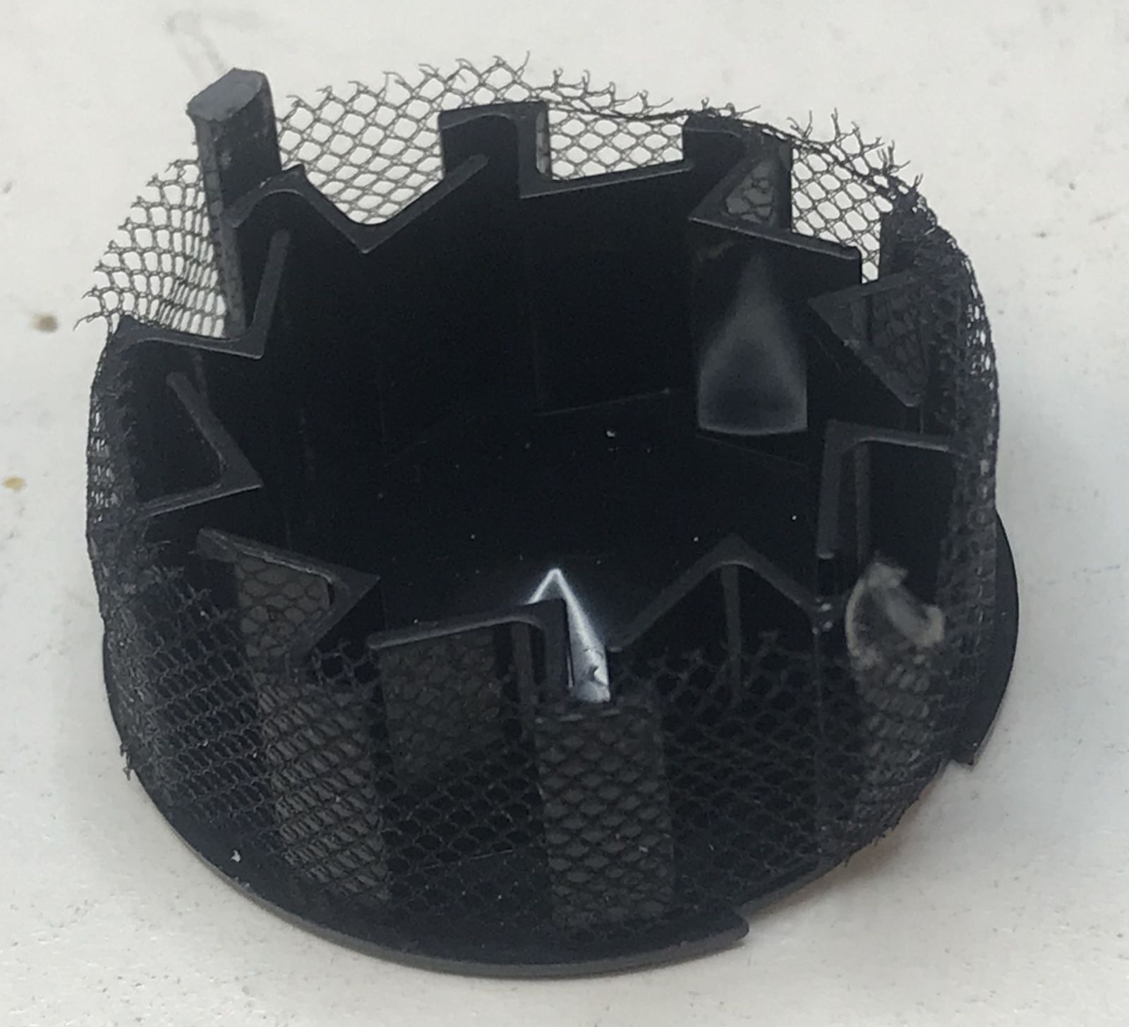
The back of the PCB contains what I call the smoke chamber:
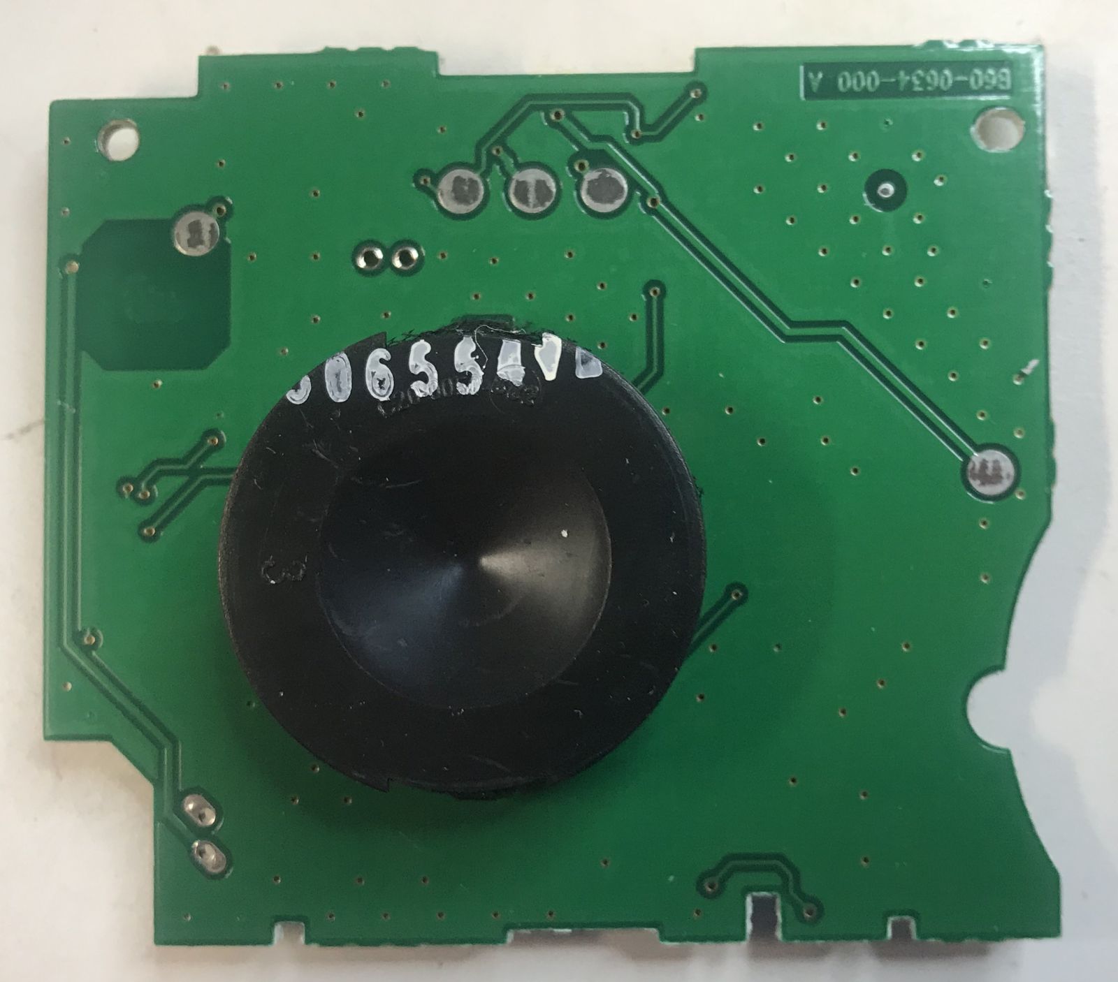
The smoke chamber attaches to the PCB with 2 plastic clamps:
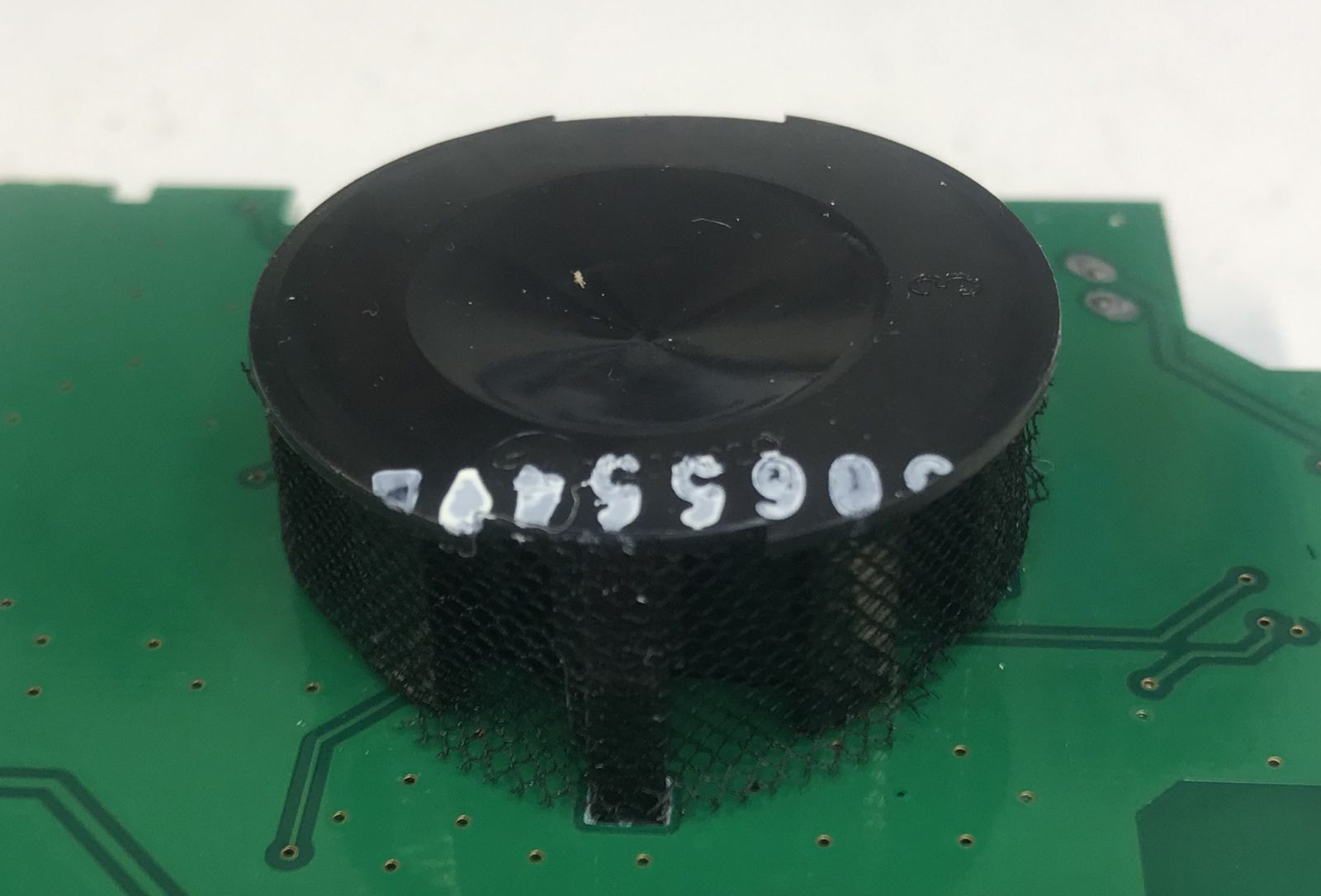
It is surrounded by some fine mesh fabric, probably to prevent tiny mosquitos from entering? There are narrow slits to let air in and out, and there are corners so that stray light doesn’t enter the center of the chamber:
Here’s a close-up of the IR emitter detector:
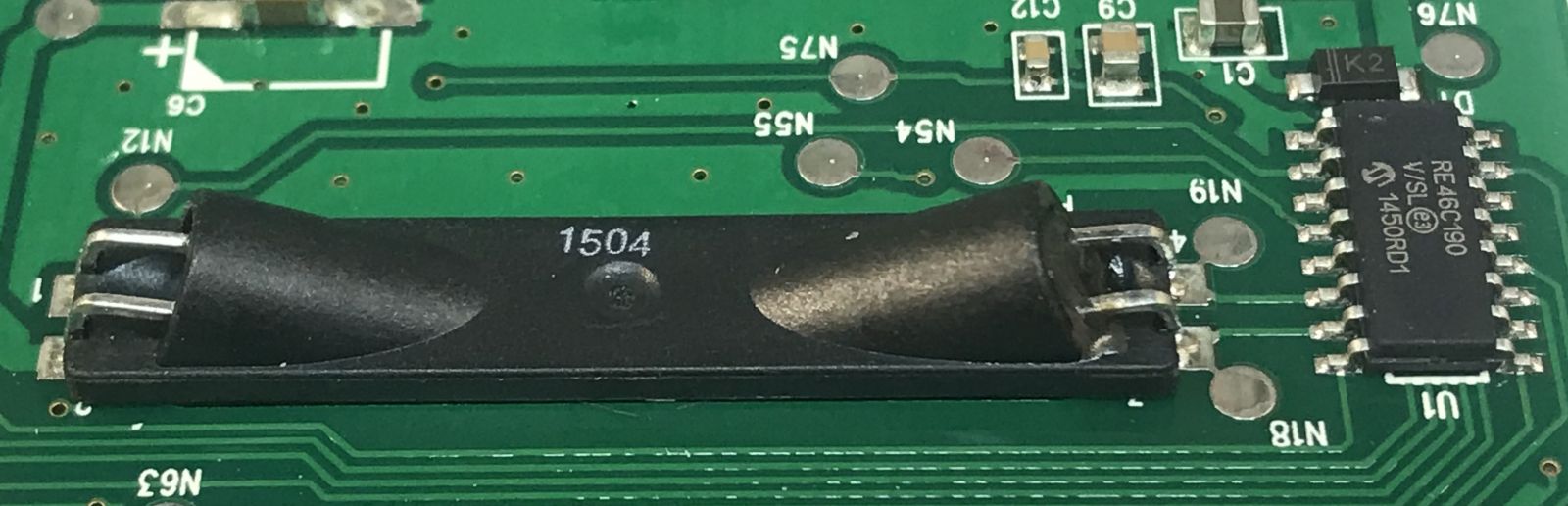
I’m not sure if smoke in the smoke chamber will result in more or less IR light being reflected into the detector…
Electronics
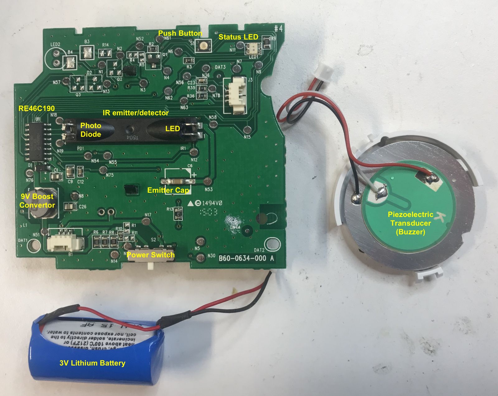
Here’s the front of the PCB again. It is pretty simple.
We’re seeing:
- the IR emitter/detector
- an RE46C190 IC from Microchip
- a power switch
- a push button to (temporarily) silence the smoke detect again
- connectors for the battery and beeper
- a switched power supply
The RE46C190 is a dedicated ASIC for these kind of smoke detectors. No other active components are needed to build one. Even at a low volume/high markup vendor like DigiKey, it sells for only $0.99 a piece when buying a minimum of 2600, so the real cost for mass production is probably significantly lower.
In normal operation, it triggers the IR emitter and detector once every 10 seconds and stays in deep sleep in between to save power. When it detects smoke, the polling rate is increased to verify that there is indeed an alarm condition.
When there are number of consecutive alarm conditions, the beeper is enabled.
The boost convertor is an important piece of the whole machinery: powered by a 3V battery, it’s used to create a ~6V voltage for the LED emitter pulse, and a 9V voltage to trigger the piezoelectric transducer.
Vbst is the output of the boost convertor. Here you can see the full cycle from powering up, to sending IR pulses, to transmitting 3 beeps on the buzzer:

Here you see the Vbst, Vemitter, and Vdetector on a larger time scale:
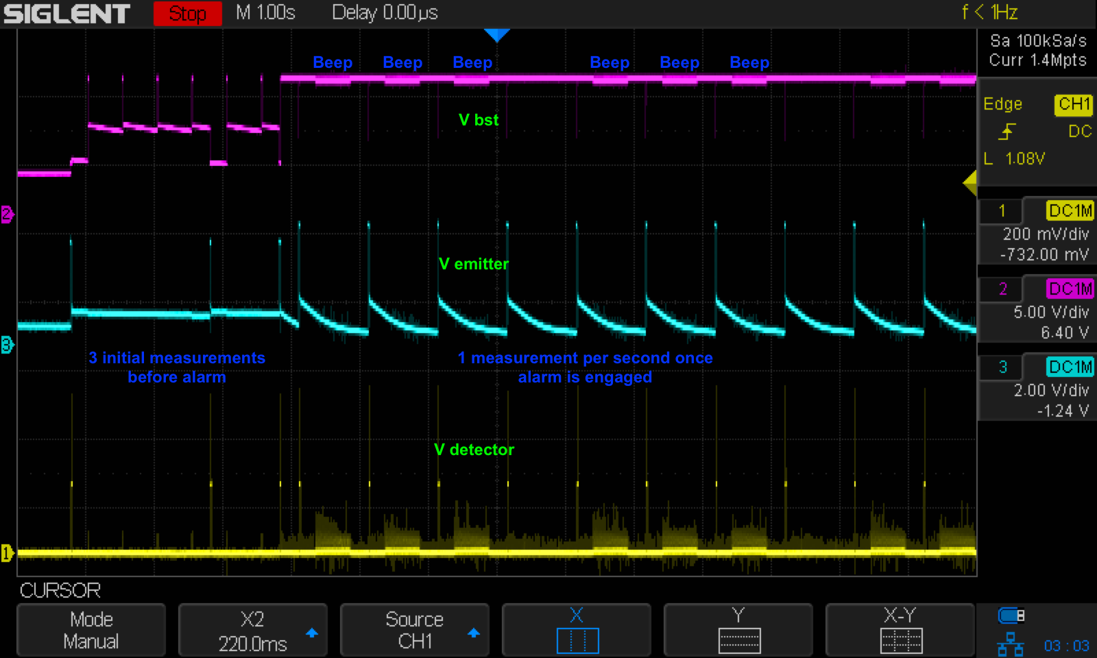
After 3 initial measurements, the alarm engages. Once that happens, the detector will recheck once every second until the smoke is gone. It’s hard to see on the image above, but when the alarm is engaged, Vbst is constant at 9V: the output falls back to 6V right around the time of the measurement.
To active the emitter, the controller charges capacitor IRcap (C6 on the PCB) for 10ms. It then drains this capacitor for a time between 100 and 400us through the infra-red LED. During that time, the current through the IR detector is integrated, digitized, and rcompared against a reference value that was programmed into the IC during calibration.
The voltage on the detector is on the order of ~100mV. Each controller has an on-chip EEPROM for various settings, including the sensitivity of the IR detector. During production, each smoke detector is individually calibrated to set the correct point at which is supposed to started making a ruckus.
Buzzer - Piezoelectric Transducer
I know nothing about piezoelectric transducers, other than that they’re loud and annoying when they go off in a smoke detector, preferably in the middle of the night.
Piezoelectric transducers can work as a loudspeaker or as a microphone: when a voltage is applied, they produce sound, and when they are subjected to noise, they’ll generate a voltage. So far so good.
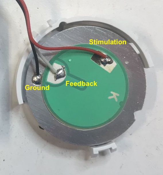
But I was suprised to see that the transducer had 3 leads instead of 2. This doesn’t have to be the case: there are plenty of transducers with only 2 leads. In that case, the electronics will drive the transducer with an oscillator to create the desired buzzer frequency.
However, that’s not necessarily ideal for an alarm: each buzzer has its own resonant frequency, and you get the highest volume, a good thing for an alarm, when you stimulate the transducer at exactly that frequency.
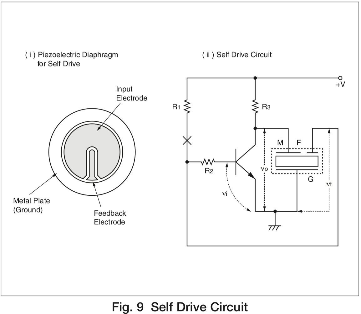
Rather than programming this frequency in the chip, people use transducers with a feedback electrode: the main wire is used to stimulate the transducer and the feedback electrode measures what was stimulated. When these 2 operate 180 degrees out of phase, you can create a circuit where the transducer itself is part of the feedback loop.
Result: the buzzer will always beep at its resonant, most efficient, frequency!
This is the so-called “Self Drive Mode” of a transducer. It uses a Hartley oscillator.
You can read all about this Murata’s Piezoelectric Sound Components Application Manual.
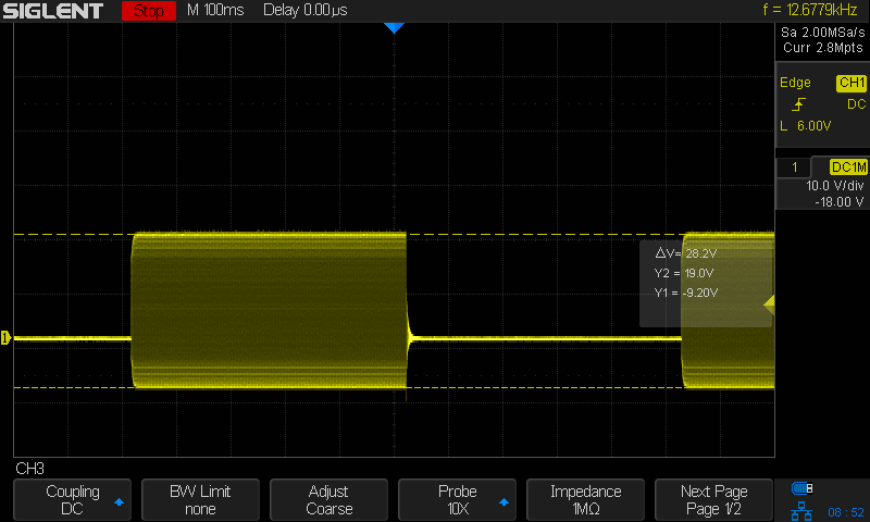
One surprising thing about this feedback wire is that the voltage on it is much higher than the 9V that was used to stimulate it: I measured a peak to peak amplitude of 28V, which falls just within the range that’s supported by the controller IC.
Conclusion
Unexpectedly, I learned something completely new about transducers! Even the most mundane product can have interesting aspects once you start looking under the hood.