Project Mc2 Pixel Purse Teardown
The disassembly of a pretty trivial toy got a bit out of hand. :-)
- A Tweet in the Morning
- Disassembling the Whole Thing
- LED panel P6 32x16
- Main PCB
- SPI PROM contents
- HUB75 Capture
- Audio Upload Interface
- DC/DC Converter
- Power Consumption
- Next Steps
A Tweet in the Morning
It started with this:

A useless gizmo for only $6.16 where one part is worth more than the whole thing combined? Irresistable!
The next day this abomination arrived:
![]()
Calling this a purse is a stretch. It’s piece of hard plastic that only looks the part. Barely.
But it’s all about the LED screen on the other side:
![]()
Taking pictures of a scanning LED display with the scanning camera of an iPhone doesn’t work very well. In the real world, your eyes should see a solid image.
The purse comes with a bunch of built-in patterns and animations. You can create new ones through an iPhone or Android app.
Disassembling the Whole Thing
There are teardown videos on Youtube, but it’s super simple: just a matter of removing a bunch of screws.
![]()
![]()
So what can we find inside? It’s really very simple:
- 4 AA batteries
- A 3-way power switch
- A button to switch between patterns
- a P6 32x16 LED panel
- the main PCB with all the electronics
- audio plug to download images from your phone to the purse
LED panel P6 32x16
A P6 panel has an LED pitch of 6mm. Multiplied by the number of LEDs that gives 192mm x 96mm.
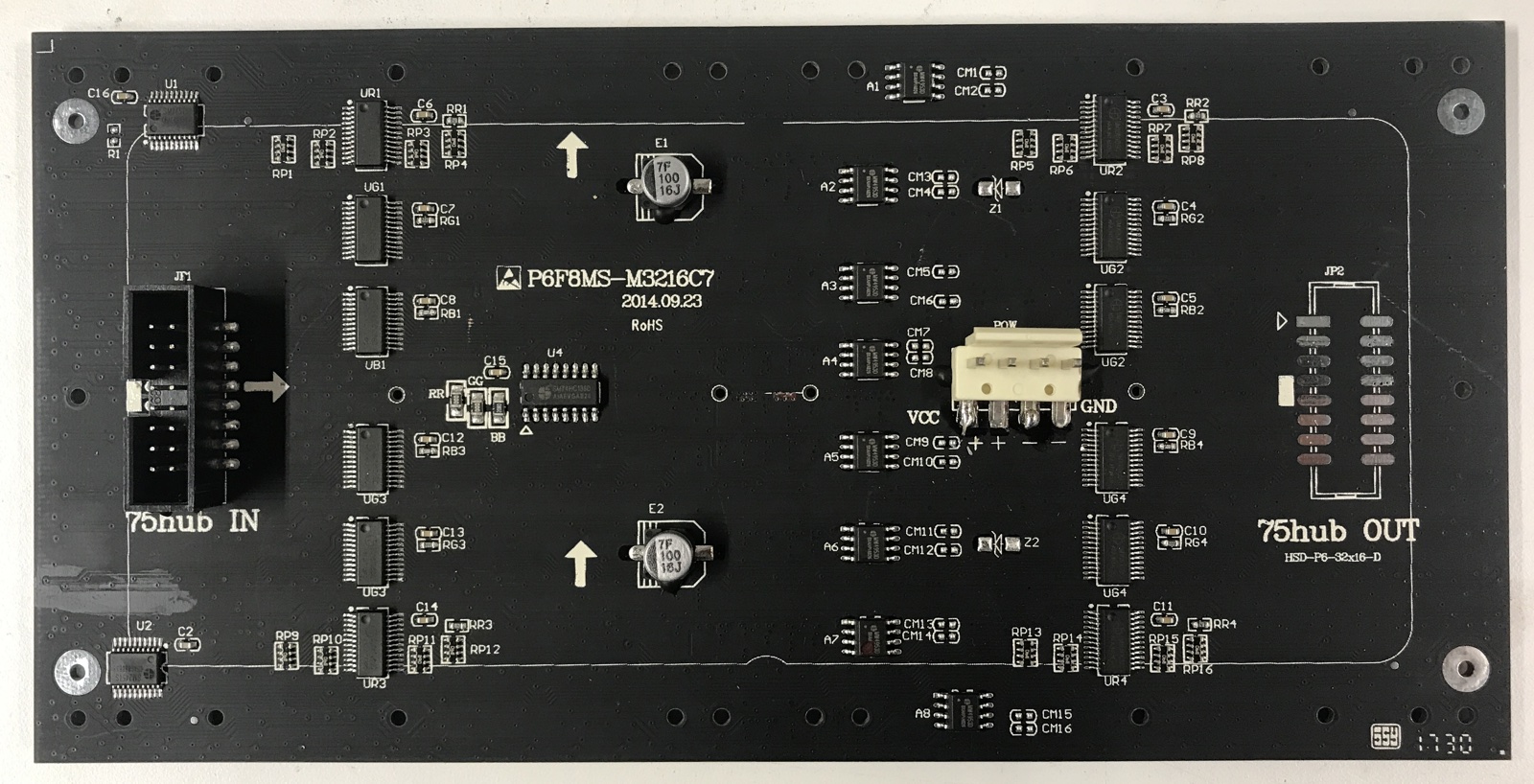
This panel is the reason why this purse is such a good deal: on Adafruit, it sells for $25. On AliExpress, you should be able to find one for ~$14 including shipping.
The panel has a standard HUB75 interface with 3 row address lines.
With 3 address lines you can select 8 rows. With 2 parallel RGB shift register inputs, you end up with 16 rows, just what you’d expect for a 32x16 panel.
Important: The 2 upper address lines D and E are not floating, but tied to ground. You need to double check when connecting this panel to a generic HUB75 driver that these pins are not driven to avoid a short-circuit condition!
Unfortunately, the panel only has a HUB75 input connector, but the output connector has been left unpopulated.
If you want to daisy chain multiple panels, you’ll have to solder a connector yourself.
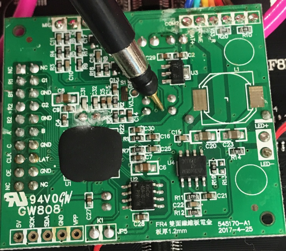
Main PCB
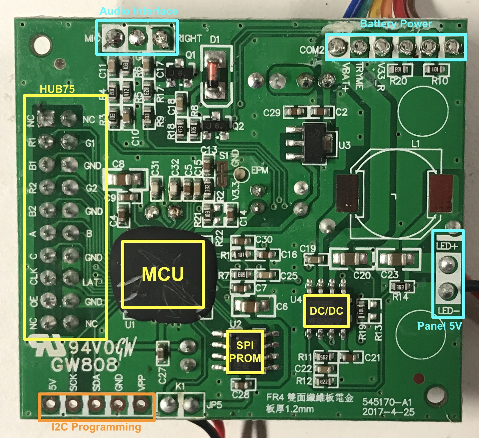
The controller PCB is spartan, with the following major components:
-
microcontroller
The microcontroller is buried under a blob of hardened plastic. Nothing is known about it.
-
4Mbit SPI PROM
XinCore F40A-104GIP
-
DC/DC converter
AP3502E - 340kHz, 2A Synchronous DC-DC Buck Converter
-
HUB75 connector
-
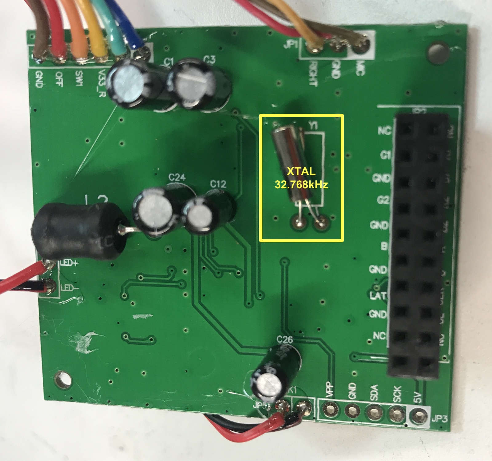
32.768kHz Xtal
There are connectors to switches, battery power, and to feed a regulated 5V to the LCD panel. But there’s also an unused connector with I2C and ‘VPP’ labels. There’s little doubt that these are used to program the microcontroller during production.
SPI PROM contents
I hoped to be able to repurpose the whole board by reprogramming the microcontroller firmware, so I dumped the traffic of the SPI during operation.
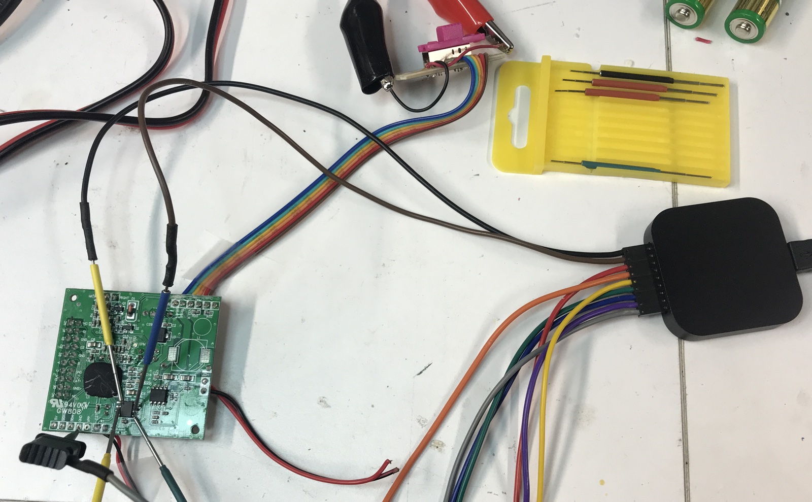
In the past, wiring up the small IO pins of the SPI PROM would have been enough of a hassle to just not bother, but with my micro clips (see my review here), it takes just a few minutes to do that:
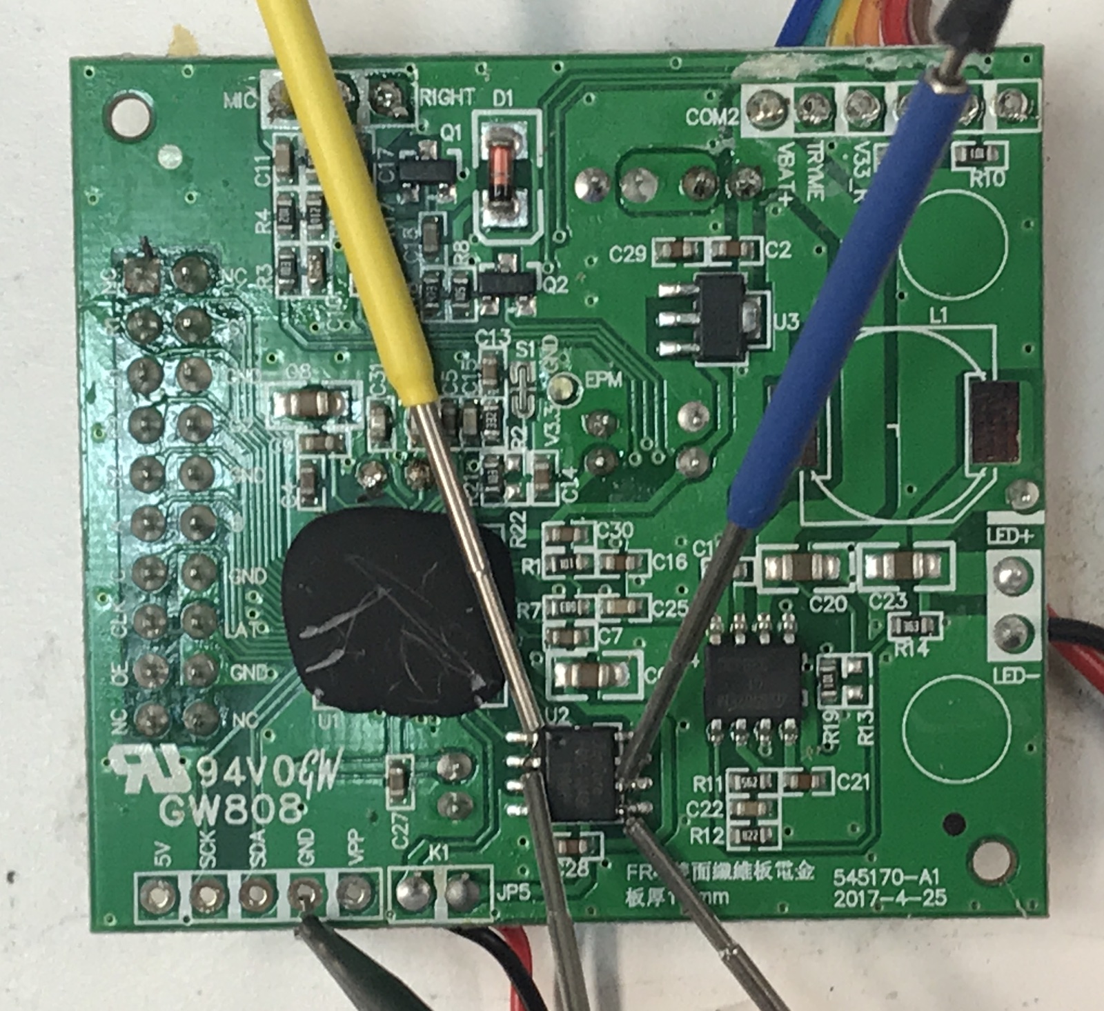
Connect it to a Saleae logic analyzer, and you’re good to go!
The overall SPI activity profile from initial powerdown (pressing the front button) to complete power down looks like this:
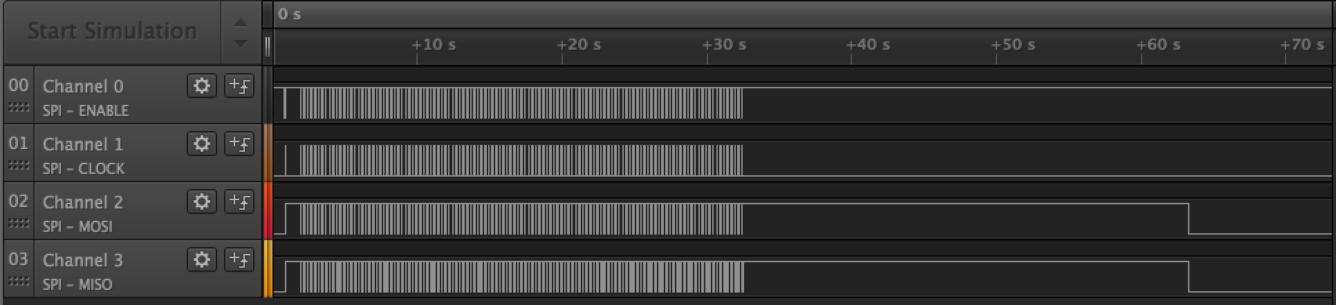
It takes about 1s to go from powering up the SPI IO pins to traffic. This traffic continous as long as the LED panel is lighted up. After 30s, the traffic stops, and another 30s later, the SPI IOs power down.
When you zoom in, there is constant repetition of a burst followed by an idle phase.
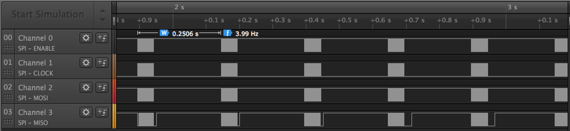
The period of this repetition is 250ms, or a 4Hz. That’s way too slow for a single refresh of the LED panel, so I think this is the rate at which the purse cycles between different frames of an animation.
The microcontroller has probably enough memory to store a single 32x16 pixel image, but loads the data for a different image on-demand.
This theory didn’t really last long when I looked at the SPI data for a case where I rotate between 3 different animations. The first and the third one behave as expected, with a pattern repeating at 4Hz.
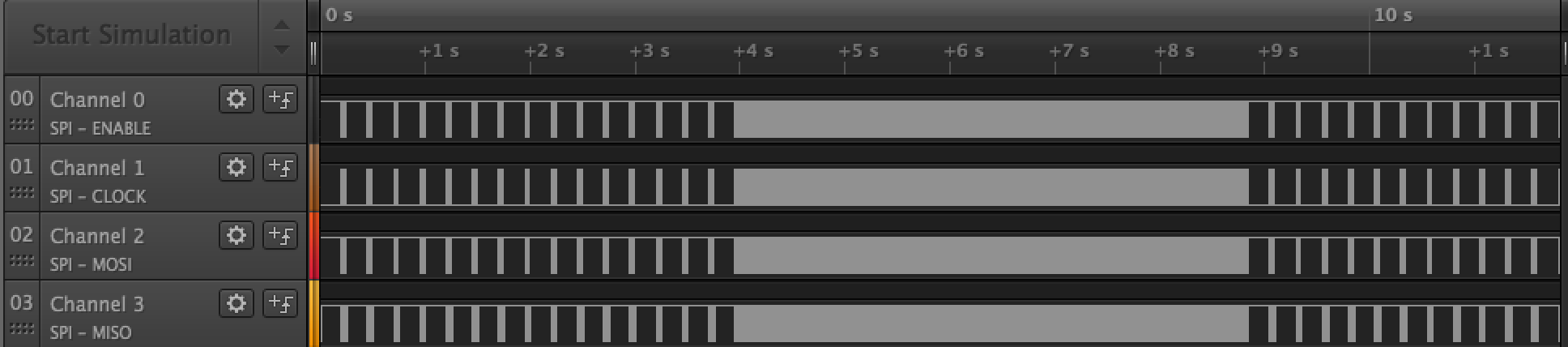
But the middle pattern does not, and is much busier:
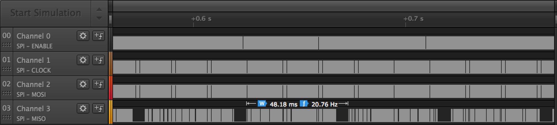
There is a somewhat repeating pattern every ~48ms.
I didn’t go any deeper into analyzing the exact format in which the frame are stored in the SPI PROM.
Unfortunately, the SPI dump does not contain anything that looks like a firmware. That removes much of the hope to rewrite the firmware for our own purposes.
It might be possible to capture the firmware through the I2C programming interface, but I did not try that.
HUB75 Capture
I also wanted to see if there was anything special about the signalling on the HUB75 interface.
Looking at another Saleae capture, you can see that there’s repeating pattern with an overall period of 15ms. That’s the overall screen refresh rate. During this time, the 3 address lines rotate through all 8 combinations, thus refreshing all the rows of the panel.
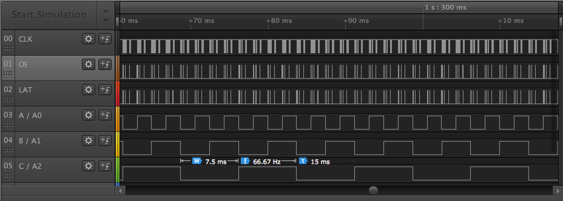
15ms for 8 addresses means 1.875ms per address.
Zooming in to a single address phase, we see the following:
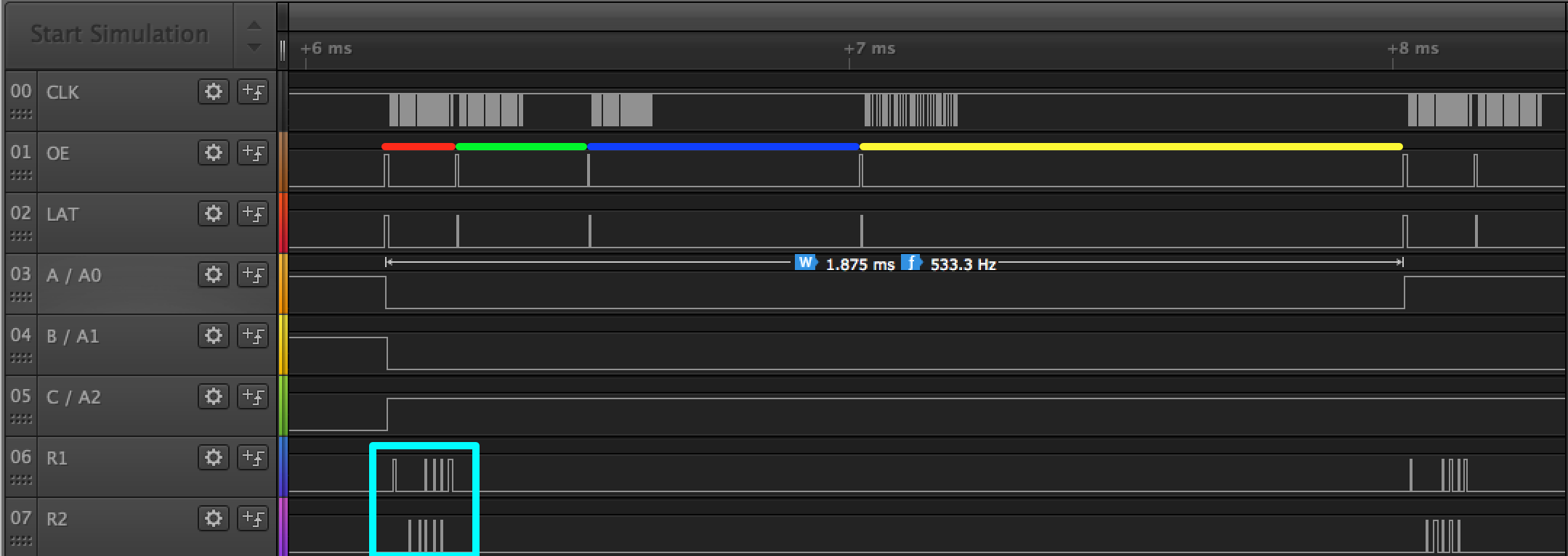
There are 4 phases (marked red, green, blue and yellow), each double the duration of the previous one.
During each phase, the clock is toggled 32 times: the number needed to shift in all the 1-bit RGB values for each LED of the address row.
However when you look at the rectangle in cyan, color values are only shifted in during the shortest phase. During the other phases, zeros are being shifted into the column drivers.
What’s happening here is the following: the microcontroller firmware was designed to support 16 color shades per pixels, hence the 4 phases of increasing duration. However, the pixel purse only supports images with 8 colors: the primaries R/G/B are either on or off.
Those primaries are assigned to the LSB of the 4-bit color shade. This has a major benefit that the LEDs are only driven 1/16th of the normal row active time of 1.875ms, thereby saving a considerable amount of power. Even this low ON duty cycle is sufficient for the pixel purse: it doesn’t need the light output of an LED panel that was design for huge video walls.
To learn more about driving LED panels with a HUB75 interface, you should read this excellent article on Sparkfun.
Audio Upload Interface
I was particularly interested in how images are uploaded through the audio interface. The overal process is simple: you enter a new image on an iOS or Android app, you insert audio plug in your phone or iPad, and off you go.
It’s a much system that doesn’t require any complex protocol like USB and thus very cheap to implement.
The overall process looks like this:
Here, uploading takes about 7s, but that’s for an animation with multiple images. (A single image takes only 1 second.) When not uploading, the iOS app sends a heartbeat pulse every 2 seconds.
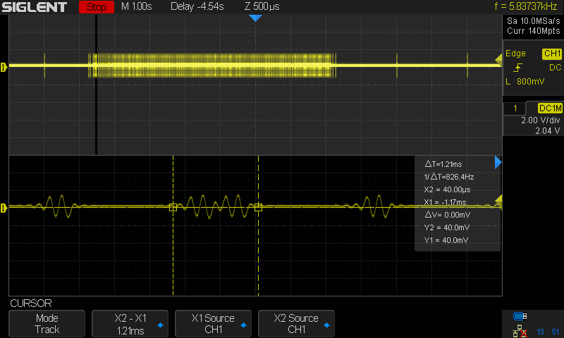
The heartbeat pulse shows how data is encoded:
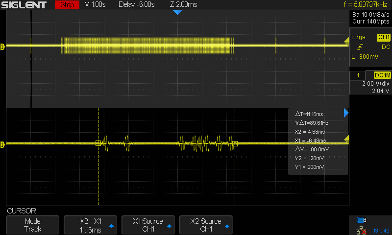
The encoding seems to be using ON-OFF keying.
In the image below, you see how 2 consecutive ‘1’ bits are encoded. It takes 1.2ms for the 2 of them, so we have a transfer BW of 0.6ms per bit or 1.6kbps. 0.6 x 32 x 16 x 3 = 0.9s, which corresponds nicely with the time to transfer 1 image.
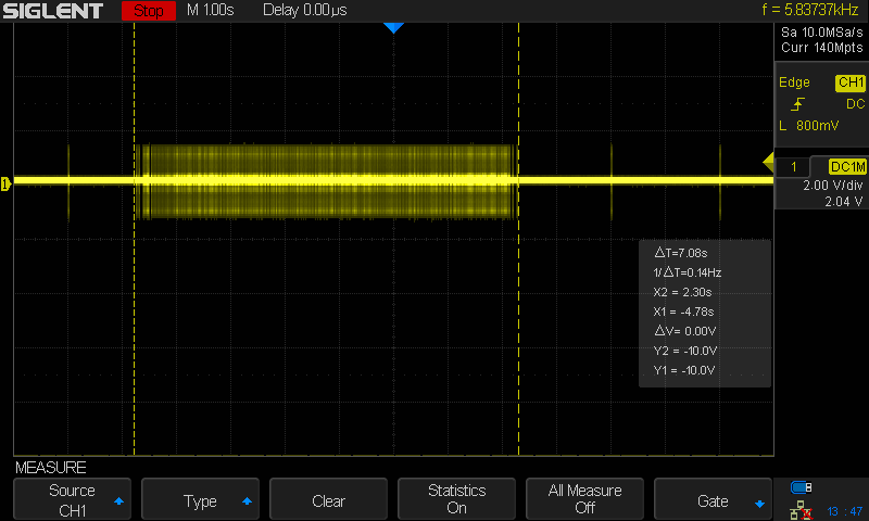
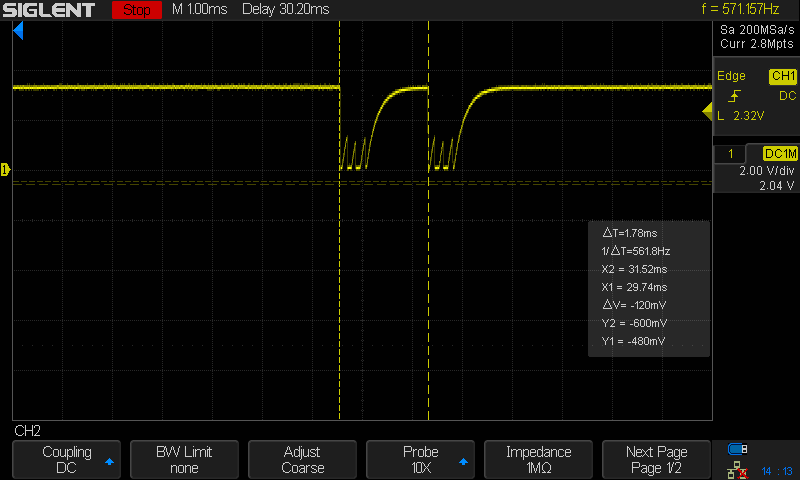
I tried to follow the signal path of the incoming audio signals all the way to the microcontroller. The last point I could find was this one:
At that stage in the process, the signal looks already nicely digital. That’s probably sufficient for the microcontroller to decode.
DC/DC Converter
The whole device is powered by 4 AA batteries, good for a maximum of ~6.5V going down to ~5V when the batteries are discharged.
A DC/DC converter generates a constant 5V, which is routed to the panel with some crude soldering of the wires straight onto the panel power connector.
Power Consumption
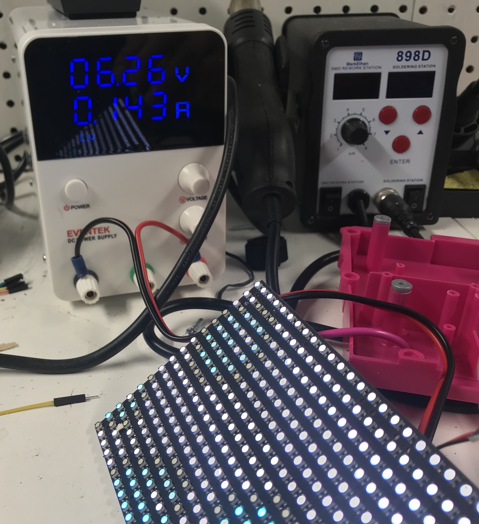
I did some crude power measurements by cutting off the batteries and using the current readout of my bench power supply.
With the power switch set to ON, but the device in deep sleep (which happens after not pressing any buttons for 30s), power consumption was essentially zero.
Once activated, and with a voltage set to 6.2V, the device consumes between 30 and 150mA depending on the image shown. There is no image with all LEDs on white, so the maximum is probably somwhere around 180mA. Using 4 AA batteries with 2200 mAh capacity each, this should result in a worst case usage of about about 50 hours, much higher than one would expect.
For fun, I lowered the voltage of the power supply to see when things would start to fail. This happened around the 4.2V mark.
Next Steps
That’s it for the teardown.
Stripped from all the ugly plastics, I have now a cheap LED panel that’s ready to be used for a project.
The only problem is trying to come up with something fun to build. Until then, it goes into the Big Box with Components.
For those who want to dig deeper and analyze the SPI capture traces, they can be found in this GitHub repo.