Guide Technology GT300 Frequency Standard Teardown
- Introduction
- Inside the GT300
- MC1403 Voltage Reference and OCXO Tuning Circuit
- LM317 Voltage Regulator Basics
- GT300 Voltage Regulation Loop
- Output Stage
- OCXO Aging
- Inside an OCXO
- Calibration Procedure
- Epilogue
- Reference
- Footnotes
Introduction
I’ve gathered a fair amount of test equipment over the years and quite a bit of them have an oven controlled crystal oscillator (OCXO) inside. There’s also the TM4313 GPSDO that I took apart last year.
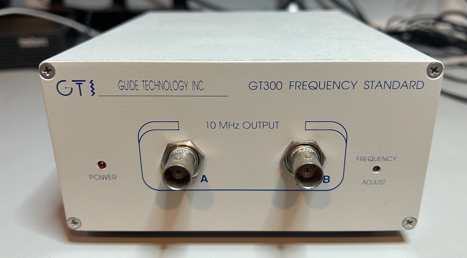
But none of these serve as my lab’s central 10MHz reference clock generator. For that, I use this tidy little box: a GT300 frequency standard from Guide Technology Inc., another Craigslist acquisition from one of my favorite equipment suppliers.
There are a few reasons why I’m using this instead some of my other references:
- It has an aged, low drift OCXO. The previous owner even ran some long-term tests to check the PPM deviation over time.
- It require a cable from my cave to a GPS antenna outside the house.
- It has two active outputs, which is usually enough for my use cases.
- It’s small enough to sit on my desk without taking up valuable space.
- It consumes much less power than my boat anchor-sized equipment with built-in OCXO. I can leave the GT300 on at all times.
An OCXO based reference standard is really simple. All you need is the OCXO itself, a power supply, and a voltage trimming circuit to calibrate the output against a GPSDO.
The unit came with schematics. There’s not a whole lot to learn, but why not give it a good look anyway?
Let’s first get this out of the way: I have absolutely no need for an accurate frequency standard. There’s nothing in my hobby activities that requires measuring frequencies with 10 digit accuracy, I use my RF signal generators only to play with them and learn how they work, and while my spectrum analyzer is pretty good for hobbyist use, it’s not good enough to measure peaks with 10 digit accuracy either.
But there’s just something fascinating about being able to make measurements so precise, and the idea of not doing that when you have the ability to do it is kind of unbearable. I guess that puts me at a high risk of becoming a time nut.
Inside the GT300
 (Click to enlarge)
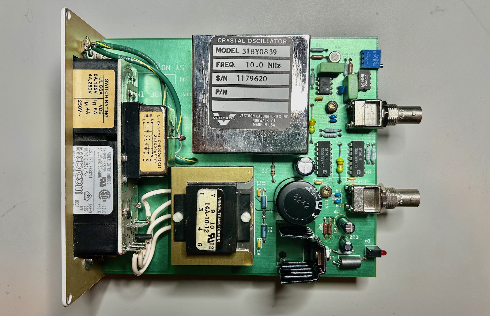
As could be expected, neither the PCB nor the schematic tell a complicated story.
- The main voltage first goes through a line filter and then into a transformer.
- The output of the transformer is rectified into a crude 9V DC voltage.
- An LM317T voltage regulator generates a 5V power rail for most components, but there’s a twist.
- An MC1403 voltage reference outputs a very stable 2.5V output.
- Opamp LT1013 is used to drive the tuning port of the OCXO.
- A couple of 74ACT00 gates serve as amplifiers to drive a low pass filters before connecting to two outputs with opposite polarity.
 (Click to enlarge)
MC1403 Voltage Reference and OCXO Tuning Circuit
OCXOs have a frequency adjust input, often called EFC for electronic frequency control, to tune the output frequency to the desired value. The tuning range is minimal: it’s not usually for the range to be less than 1Hz. To ensure sufficent accuracy, the voltage at the frequency adjust input must be low noise and very stable. Deriving this voltage from a resistive divider between the power supply and ground will not do.
The GT300 uses the obsolete MC1403 voltage reference.
 (Click to enlarge)
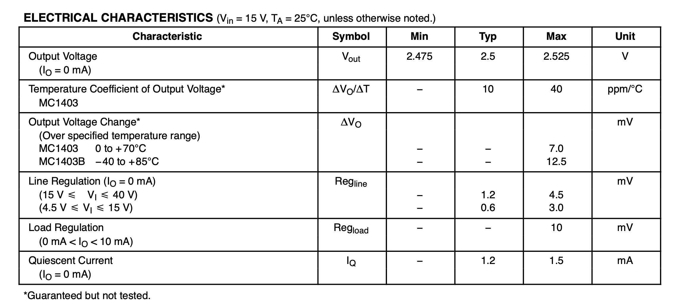
It has an output of 2.5V and a typical temperature coefficient of 10ppm/C. A 5C temperature difference will change the output by 1.25mV or 0.05%. Not a lot, but higher than the 4 digit accuracy that’s needed to maintain that 10-10 OCXO precision.
It shows that even with a voltage reference, it’s still important to locate the reference in a room that doesn’t have large temperature swings.
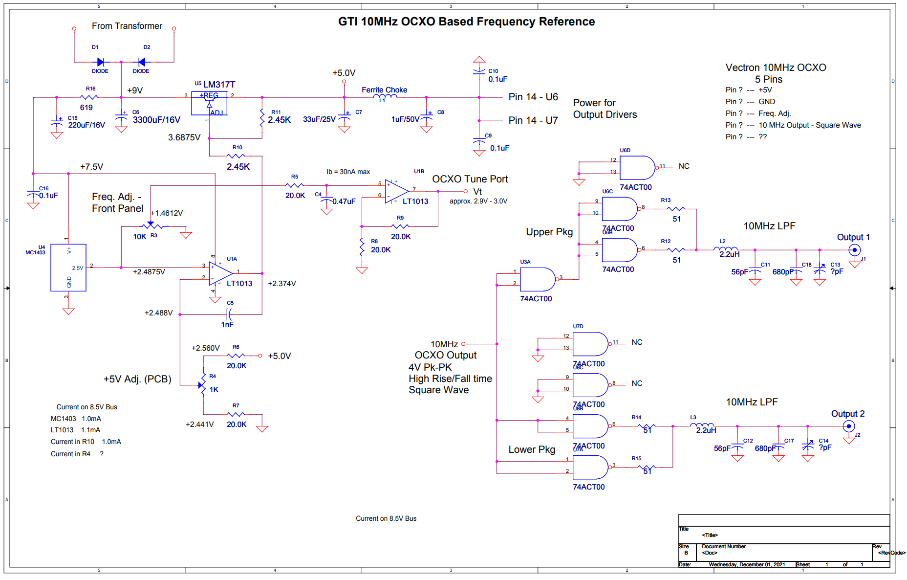
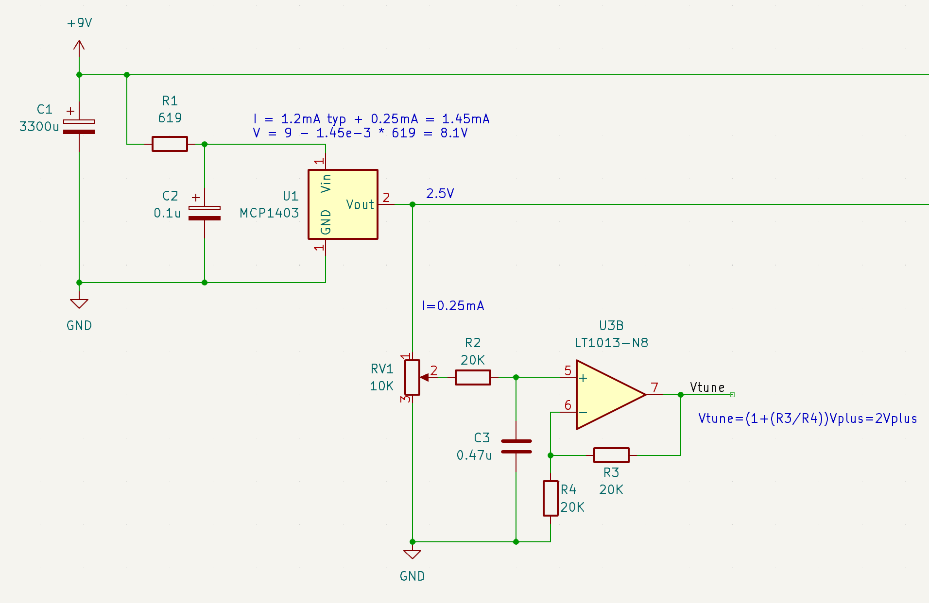
I redrew the schematic in KiCAD to make the component arrangement a bit more logical, with some math annotations to confirm the values of the schematic:
 (Click to enlarge)
\(V_{in}\) of the MC1403 is indirectly connected to the the unregulated 9V instead of the regulated 5V. I think there’s two reasons for this: the electrical characteristics of the MC1403 are specified for 15V. 5V may be too low to achieve the listed specification. But another one could be that the 5V itself depends on the 2.5V reference. I’ll get into that later.
The diodes and input capactior form your usual AC to DC rectifier with ripple attenuator, but there’s an additional RC low-pass filter in the form of R1 and C2 to eliminate higher frequency noise. The combination of R1 and the current that’s going through MCP1403 and trim potentiometer RV1 creates a \(V_{in}\) voltage of around 8.1V.
The output of the reference goes to trim potentiometer RV1 with a control screw that’s accessible on the front panel. This is the screw to turn when you want to calibrate the output frequency.
LT1013 is a low temperature-drift opamp. It doubles the 0 to 2.5V output range of the potentiometer to the 0 to 5V range of the OCXO frequency adjust input.
LM317 Voltage Regulator Basics
The GT300 uses an LM317 voltage regulator to create a stable 5V supply for the OCXO, but the circuit is a bit more complicated than what you’d expect.
The datasheet of the LM317 contains a number of application examples, but they’re all a variant of the following basic circuit:
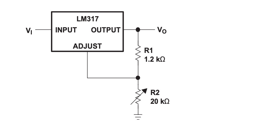
The formula of the output voltage is
\[V_\text{o} = V_\text{ref}(1+\frac{R_2}{R_1}) + (I_\text{adj} \cdot R_2)\]where \(V_\text{ref}\) is 1.25V and \(I_\text{ADJ}\) around 50uA, but it can go up to 100uA.
Instead of just accepting this formula above as gospel, I derived it myself to freshen up my college era opamp knowledge.
(You can totally skip the rest of this section…)
To do that, you need start with the block diagram of the LM317:
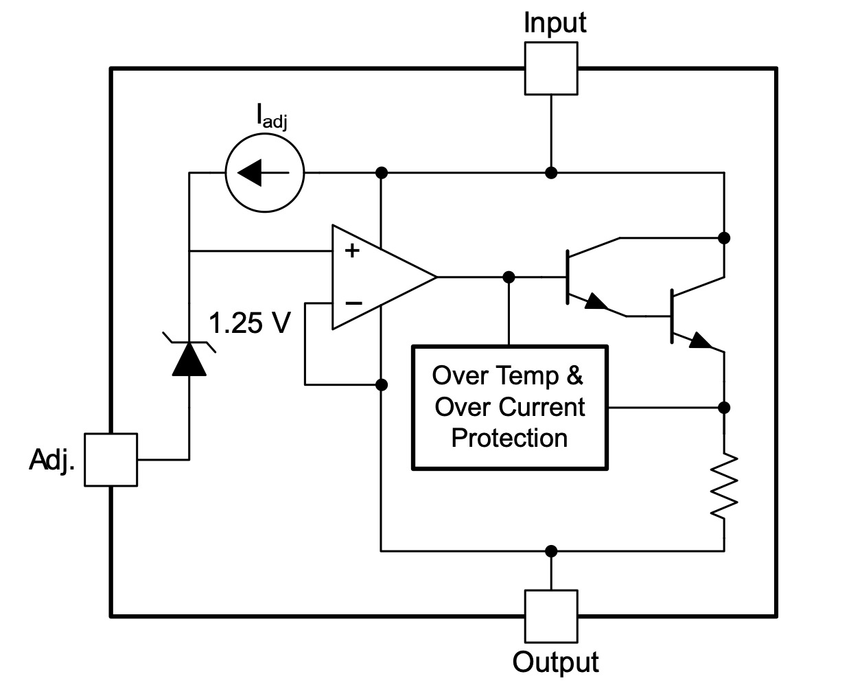
We can see an opamp, a 1.25V zener diode at the plus input, a drive transistor combo in Darlington configuration, a constant current source, and some miscellaneous protection logic.
Let’s simplify this a little bit and only keep the items that are part of the control loop:

Here’s how we get the formula:
- \(V_\text{plus}\) is the voltage at the positive input of the opamp.
- After going through the drive transistor, the output of the opamp gets fed back directly to the negative input of the opamp.
- The opamp tries to keep the positive and the negative inputs the same.
- Since this signal also goes to the output terminal \(V_\text{out}\) of the LM317, we know that \(V_\text{out}\) has the value of \(V_\text{plus}\).
- Due to the 1.25V zener, the voltage of the ADJUST input of the LM317 is \(V_\text{plus}-1.25V\).
- We can now calculate \(I_{R_1}\), the current through resistor \(R_1\).
- The current through \(R_2\) is the current through \(R_1\) plus \(I_\text{adj}\), the current from the constant current source.
- From this, we can calculate the voltage drop across \(R_2\).
- And from that, we can derive the value of \(V_{plus}\), and thus the output voltage \(V_{out}\).
In many cases, the current through \(R_1\) will be much larger than \(I_\text{adj}\), and we can just ignore the \(I_\text{adj}\) term altogether.
GT300 Voltage Regulation Loop
Thanks to its built-in 1.25V voltage reference, the LM317 can create a stable output voltage that is good enough for most applications, but the designers of the GT300 clearly wanted something better and decided to make the MC1403 voltage reference a part of the regulation circuit.
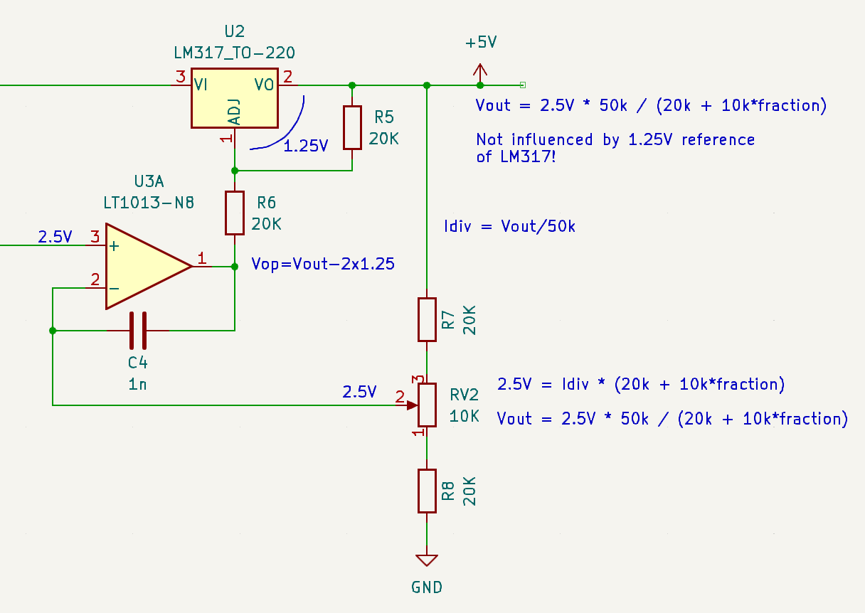
The rearranged schematic of that circuit is here:
 (Click to enlarge)
Let’s do a similar circuit analysis as before:
- The 2.5V reference voltage is applied to the + input of the opamp.
- the opamp tries keep the - input at the same level as the + input, so we can assume a voltage of 2.5V there as well.
- The - input comes from a 50k resistive divider between Vout and ground.
The steps above are sufficient to calculate Vout:
\[V_{out} = 2.5V \frac{50k}{20k + 10k . \text{fraction}}\]The other nodes of the circuit can be determined as follows, but they don’t play a role in the calculation of the output voltage:
- There’s a 1.25V difference between the LM317 VO and ADJ pin.
- The current through R5 goes (almost) entirely through R6 as well.
- Since R5 and R6 have the same value, the voltage across R6 is 1.25V too.
- All the opamps need to do is regulate its ouput, \(V_{op}\), to a value of \(V_{out} - 2 \times 1.25V\).
- C4 is present for control loop stabilization.
The important part here is that the 1.25V zener is not used to determine the value of Vout:
The output voltage is determined entirely by the much better 2.5V voltage reference!
Why then is the GT300 using an LM317 instead of a regular power transistor? I think it’s because the current circuit still benefits from the over-temperature and over-current protection facilities of the LM317.
Earlier I also wondered by the MC1403 power input was connected to the unregulated 9V power rail instead of regulated 5V. That may be to avoid some kind of chicken-and-egg problem during startup: it avoid the case where the voltage regulation uses a voltage reference that uses the regulated voltage.
Output Stage
The OCXO sends out a 4V 10MHz square wave signal. Most frequency references send out an AC sine wave instead to avoid the harmonics of a square wave signal.
Output buffer
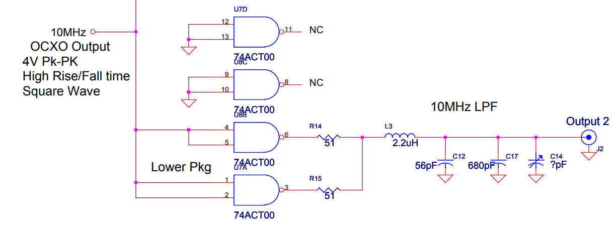
The GT300 output stage uses digital gates from the fast 74ACT series as drivers. Two gates are connected in parallel for additional strength, but the on and off delays of gates are never truly identical, so 51 Ohm resistors are added at the output to limit the current during edge transistions.
I’ve seen a couple of 74-series driven output buffer before, but I had never seen these kind of resistors added per output driver. It’s definitely not always done. Here’s the 1 PPS output buffer of an SRS FR725 Rubidium Frequency Standard, for example:
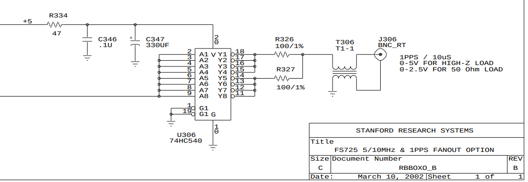
The 74HC540 is an octal buffer/line driver. The 8 buffers are driven by the same signal, split in 2 groups of 4 that are wired together, which then drive a 100 Ohm resistor.
Output filter
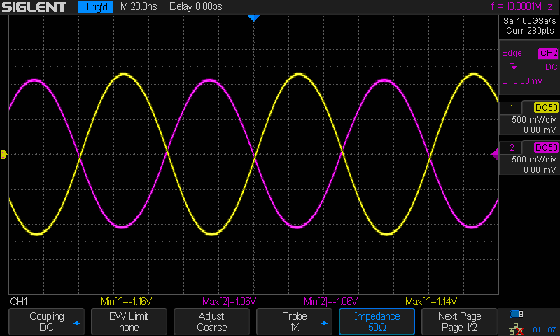
Finally, there’s an LC filter that converts the 10MHz square wave into a sine wave.
When connected to a 50 Ohm termination, the output has an amplitude of 1.06V.
A 1M Ohm termination results in a 1.5V amplitude:
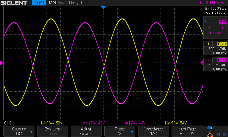
Output 1 and output 2 are inverted output due to the additional inverting NAND gate in the path of output 1.
OCXO Aging
As mentioned before, the previous owner ran a long-term test to check the aging of the OCXO of this unit.
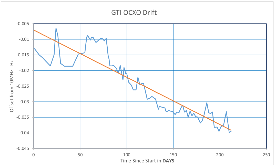
Powering an OCXO on and off is a bit of a traumatic experience for the high-precision crystal that lives inside and it’s one of the reasons why it’s better to keep them always on.
The GT300 has been sitting idle before this test was started and was then calibrated against GPSDO. In the graph, you can see that it takes 2 months before the OCXO settles into the pattern of steady drift that’s caused by aging.
The relative aging rate can be calculated as follows:
- Freq. shift @ 200 days = -0.0375 Hz
- Freq. offset at Start of test: = -0.007 Hz
- Freq. shift over 200 days = -0.0375 – (-0.007) = -0.0305 Hz
- Freq. aging rate: Delta freq / Delta time = -0.0305/200 = -0.0001525 Hz/Day = -1.525e-4 Hz/day
- Freq. aging rate relative to 10MHz = (-1.525e-4) / (10E6) = 1.525E-11
- Aging rate/day = 1.525E-11
This is supposed to be a good number, and one that can go down to the 1E-12 range when powered on uninterrupted for years. My GT300 is not connected to a UPS, and with PG&E power going down at least once per year, the chance of that happening is close to nil.
Inside an OCXO
Every OCXO has a way to tune the output frequency to the desired value. Either with a trimmer, as is the case for the GT300, or as part of a PLL of a GPSDO. The tuning range is usually quite narrow.
I don’t have the specifications or datasheet of the Vectron 318Y0839 that is used in the GT300, but the HP 10811 series of OCXOs, used in tons of old HP test equipment, has a service manual with full schematics and much more. Let’s use that for the discussion here.
There are many 10811 variants, with different specifications. The HP 10811-60111 in my flea market HP 5334A universal counter is one of the lowest rated ones, not unreasonable for a counter that never had high-end ambitions. You can see it here:
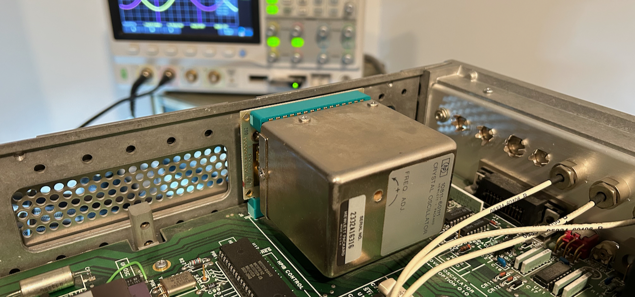 (Click to enlarge)
The 10811 has an output frequency of 10MHz and an electrical tuning range of ±1Hz, or a relative range of just 10-7. Most OCXOs have only 1 way to control the output frequency by applying a voltage on their frequency adjust input but the 10811 has two options: through its EFC input, or by changing the value of a trimmable capacitor. The trimmable capacitor is used for coarse tuning and can change the output frequency by ±20Hz.
Both tuning methods are highlighted in the schematic below:
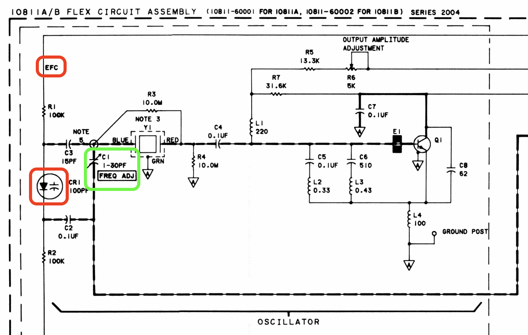 (Click to enlarge)
The trim capacitor is circled in green. The EFC circuit is marked in red.
Fundamentally, the EFC circuit and the trim capacitor achieve their goal the same way: they change the resonance frequency of a Colpitts oscillator by adjusting the capacitance of the oscillation loop.
In the case of EFC, the variable capacitance is a varicap diode, a diode with a capacitance that depends on the reverse bias voltage.
Sections 8-13 though 8-39 of the service manual has an in-depth explanation of the oscillator theory of operation, output impedance matching, voltage references, and more. Highly recommended!
Calibration Procedure
Calibration of a frequency reference needs to happen with something that’s even more stable. In my case, I calibrated the GT300 against my TM4313 GPSDO that had been running for a couple of days.
The procedure is very simple: just throw the output of a GT300 and the GPSDO on an oscilloscope and turn the potentiometer until the 2 waveforms are static against each other. It’s doable to tune the output with 9 digits of accuracy that way.
Here’s what the signal looks like when the GPSDO is outputing 10MHz and the GT300 is outputting 9,999,999.97MHz.
Once you go down to the 9,999,999.99MHz, it takes some time to see how much the curves are moving relative to each other. In the video below, the intersection of the two curves is drifting slowly to the right:
For even better tuning, you need to bring out bigger guns such as the 12 digit SRS SR620 frequency counter1.
It takes a good amount of finessing the potentiometer, but eventually I was able to get the GPSDO and the GT300 to match down to the 1mHz accuracy:
At this point, opening a window is sufficient to see a change, but chances are that it’s the GPSDO that’s at fault: the OCXO inside the TM4313 is a lot cheaper, smaller and thus with a much lower thermal capacity. If the issue were the GT300, you’d see the frequency deviate in one direction but I saw the frequency counter measurements go oscillate above and below the calibrated value. That’s the control loop of the GPSDO PLL trying to adjust to the new conditions.
One day, I’ll explore that in more detail.
Epilogue
The original Craiglist ad had that graph with the long-term measurements. While writing this blog post, I emailed te seller for some more information, and he told me that he was actually the original designer of the GT300!
Reference
- Schematic
- TI - LM317 Datasheet
- Analog Devices/Linear Technology - LT1013 Datasheet
- EEVblog forum: LM317 with external voltage reference. What’s the benefit?
Footnotes
-
You guessed it: yet another flea market find! ↩