Teardown of the TM4313 GPS Disciplined Oscillator
- Introduction
- What is a GPSDO?
- The TM4313 GPSDO
- Power Consumption
- Inside the TM4313
- The TM4313 Schematic
- Frequency or Phase Lock Loop?
- OCXO Temperature
- The Curious Case of the MAX6192 Voltage Reference
- The Discrete Tuning DAC
- GPS Module
- Microcontroller instead of NMEA Serial Port
- GPSDO Performance
- Conclusion
- References
- Footnotes
Introduction
It’s a generally accepted truism that once you’ve acquired your first frequency counter, you slowly get sucked into the Cult of the Time Nuts and their never ending quest for increasingly accurate time measurements.
In my previous blog post about high precision frequency measurements, I mentioned the need for an accurate time reference. In addition to their own internal clock generator, test equipment such as frequency counters, signal generators, spectrum analyzers etc. have an external 10MHz reference clock input so that all devices in the lab can use the same time reference.
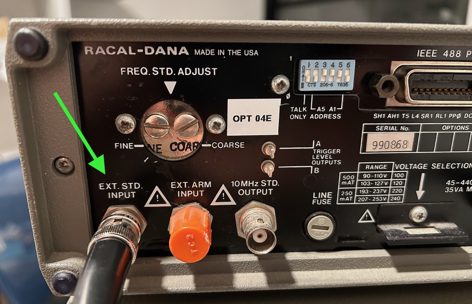
Such a 10MHz clock can be created by different kinds of devices: I have a GT300 frequency standard, for example, and ultra-stable Rubidium atomic clock modules can be found on eBay for less than $500, but ultimately you need to calibrate such a standard against a golden reference. For almost all hobbyists, the global navigation satellite system (GNSS), in its various forms1, is used as the golden reference.
In a satellite positioning system, each satellite has an atomic clock that is in turn synchronized to a central golden reference on the ground. The satellites continously transmit their time and location back to earth. A GPS receiver tries to capture the signal from as many satellites as possible, and figures out its location through trilateration: due to electromagnetic waves travelling at the speed of light, the received time stamps will be different for different satellites.
But instead of using the satellites’ time stamps to derive a location, you can also just use them as a very accurate time reference.
In this blog post, I’ll first discuss the principles of a GPS Disciplined Oscillator (GPSDO), and then I’ll tear down the TM4313, a $95 GPSDO that I bought new from eBay.
What is a GPSDO?
A GPSDO uses two time keeping mechanisms with complementary characteristics to create the best of both worlds: a reference clock that is accurate both in the short and the long term.
The time extracted from a GPS module is long term stable: it’s as accurate as the GPS system itself. However, the 1-pulse-per-second (1PPS) output signal often has a lot of jitter. On cheap GPS modules, the pulse-to-pulse jitter can be on the order of tens of nanoseconds.
On a signal that pulses once every second, that means the 1PPS signal has short term relative accuracy of around 10-8. For a GPSDO, we’re looking for something that’s around 10-10!
The other time keeping mechanism is the oven controlled crystal oscillator or OCXO. They consist of a crystal oscillator that is embedded inside an insulated oven, with a control circuit to keep the inside of the oven at a constant temperature to combat the temperature dependency of the oscillator frequency.
OCXO specifications vary a lot (and so does the cost) but they tend to have excellent short term jitter or phase noise characteristics. However, they are subject to various drift mechanisms. Here are some of them:
- despite their built-in oven to keep the temperature stable, the output frequency still changes when the ambient temperature changes.
- a new OCXO must run for about a month to get past its initial aging phase, during which the output frequency can change significantly.
- once sufficiently aged, an OCXO will still drift, though at a much lower rate.
OCXOs have an electronic tuning input to nudge the output frequency up and down by a tiny fraction. It’s not uncommon for the total tuning range of a 10MHz OCXO to be less than 1Hz.
A GPSDO uses an OCXO to create a stable clock in the short term, while using the GPS system to adjust the OCXO so that it also stays stable in the long term. Hence the name GPS Disciplined Oscillator: the oscillator is kept in check by the GPS system.
The TM4313 GPSDO
I stumbled onto the TM4313 while searching for GPSDOs on eBay. I hadn’t seen them before, and with a nice metal enclosure and one of the lowest GPSDO prices around, they seemed attractive.
There is almost no information about the TM4313: when you google for just the “TM4313” term, there’s tons of GPSDO related results, but none of them actually discuss the TM4313 itself, except for this one in-depth report: Comparison of Inexpensive 10 MHz GNSS Disciplined Oscillators.
It judged the TM4313 to a good-enough option, so I placed an order. Shipping time was supposed to be a few weeks, but it arrived just a few days later.
The non-descript box contained the following items:
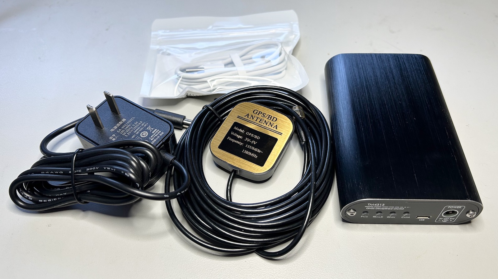
- the GPSDO unit
- a GPS window antenna with a long cable
- a USB-A to micro-USB cable
- a 5V power brick
The unit itself has a good looking aluminum enclosure with front and back plates that are aluminum as well.
The front plate has 4 blue LEDs for power status, time tracking status, GPS lock, and serial communication status.
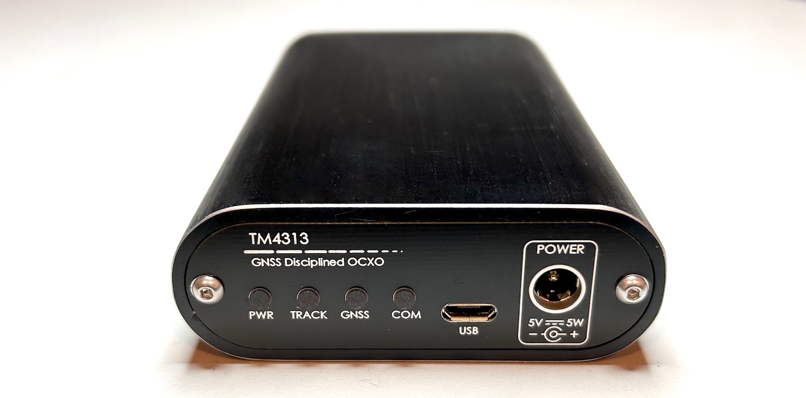
There’s a micro-USB port to connect the GPSDO to a PC, allowing you to extract GPS information, and a socket for a 5V power plug. I would have prefered the power plug to be in the back but there wasn’t any room left there.
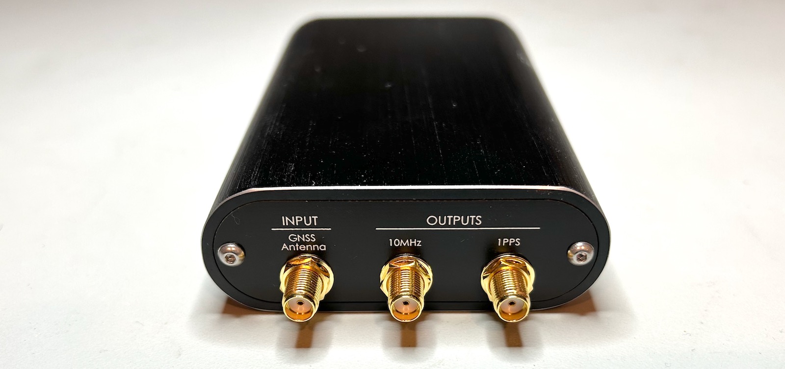
The back plate has 3 SMA connectors: the GPS antenna input, a 10MHz reference clock outputs, and a 1-pulse-per-second (1PPS) output.
There’s no standard about the signaling of a 10MHz reference clocks. They are either an AC sine wave or a digital square wave. The benefit of a sine wave is the lack of strong harmonics in the signal but on a digital square wave the edges are better defined. The TM4313 doesn’t come with a specification sheet or manual, and there is no mention anywhere about the type of output. When put on a scope, I could see 10MHz sinewave with an amplitude of +-1.1V into a 50 Ohm termination resistor.
The 1PPS output is a 5V TTL signal with 100ms on and 900ms off time.
On my oscilloscope, there was no obvious jitter between the 10MHz reference clock and the 1PPS output.
Somebody pointed me to a TM4313 datasheet.
Power Consumption
Immediately after powering up, an OCXO needs to warm up its oven. This can take minutes on large OCXOs with a high thermal capacity, but it’s very fast on the TM4313: it consumes 5.6W for about one minute after which power drops down to around 2.2W.
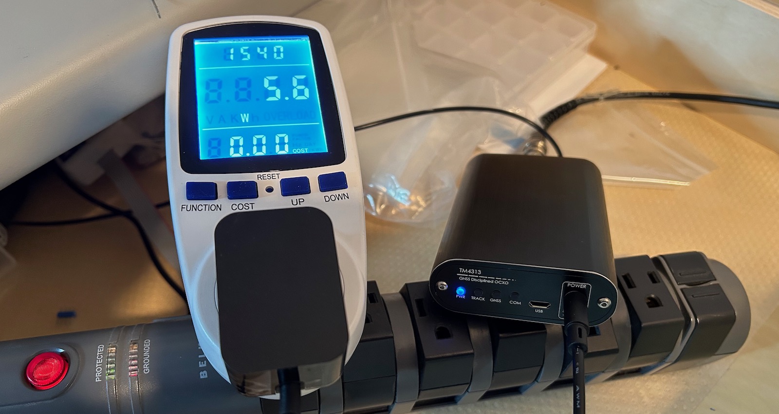
Since it can take hours for a GPSDO to reach their true stable state, it’s common for them to be stuck in a closet while powered on permanently, so it’s important to keep the power consumption to an minimum.
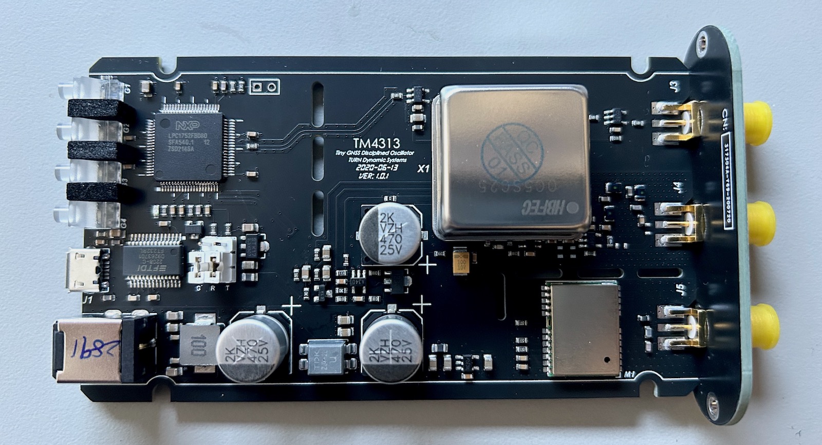
Inside the TM4313
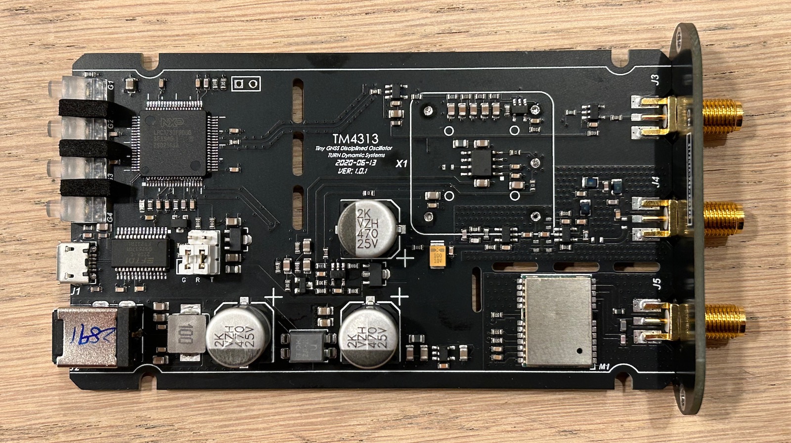
Opening the TM4313 is a simple matter of removing 2 Torx T6 screws from the front panel and sliding out the PCB.
 (Click to enlarge)
Here are the main components:
-
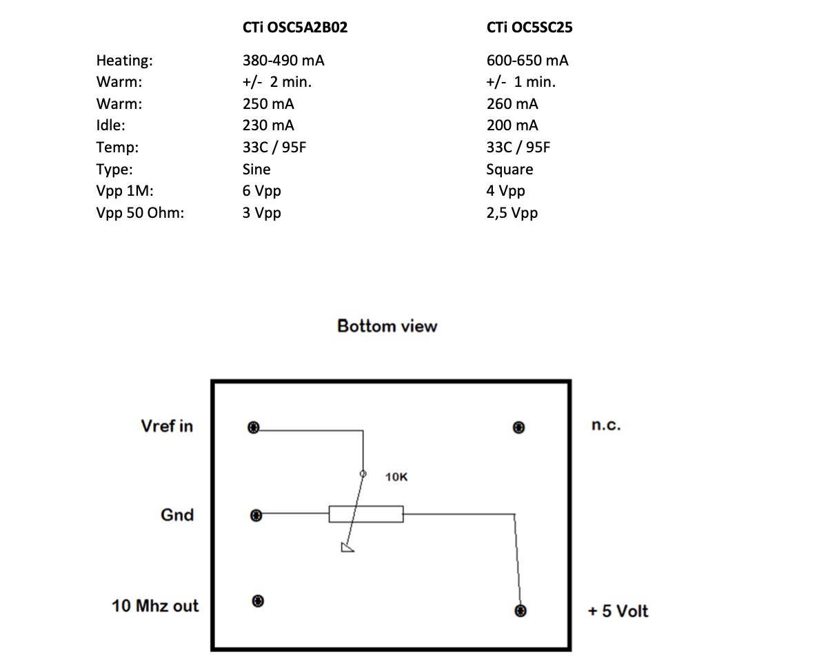
an HBFEC OC5SC25 OXCO
This seems to be a clone of a CTi OC5SC25, which can be found for just a few dollars on eBay or AliExpress. Tony Albus has the following specification sheet about it:
-
an unmarked ATGM332D-5N-31 GPS module (datasheet)
-
an NXP LPC1752 microcontroller (datasheet)
-
an FTDI232RL USB-to-serial converter
-
power regulators and some jelly-bean ICs
Is that all there is? No!
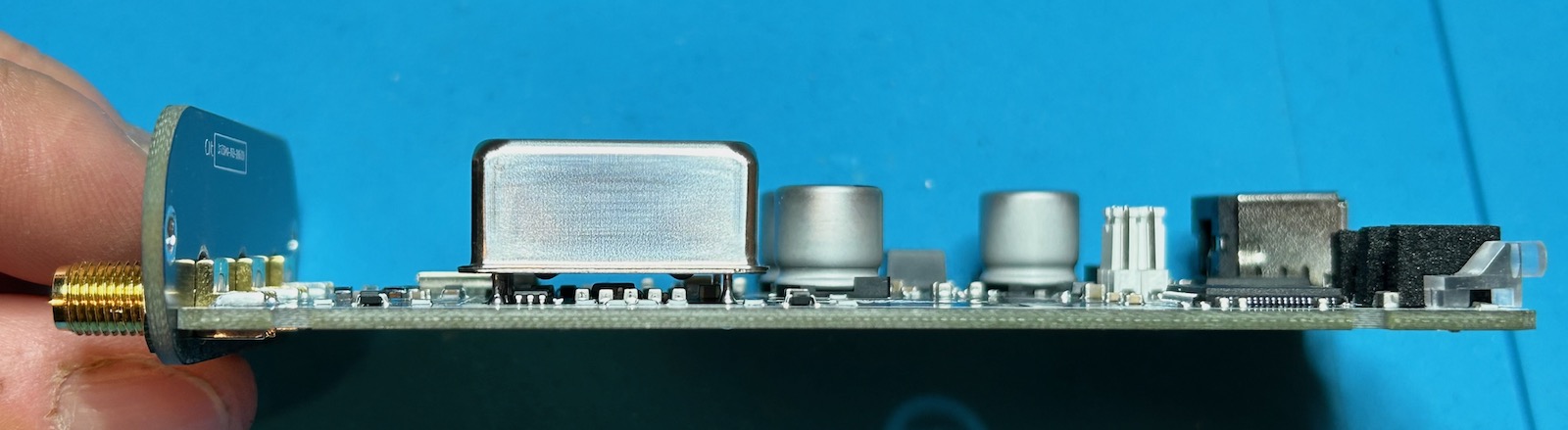
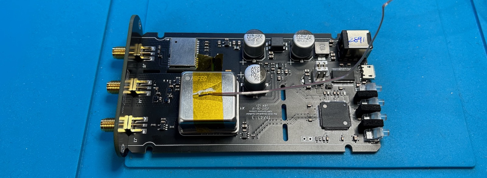
The OCXO is not soldered flush against the PCB, but floats a few mm above it. And there’s bunch of components soldered in between them:
 (Click to enlarge)
It’s common practice to leave a gap between an OCXO and the PCB to prevent the PCB from acting as a heat sink and thus changing the temperature time constant. Many OCXOs have small glass-like spacers to enforce such a gap but it’s unusual to see additional components squeezed in-between.
The urge to know what was below was too strong, so I desoldered the OCXO. This is the result:
 (Click to enlarge)
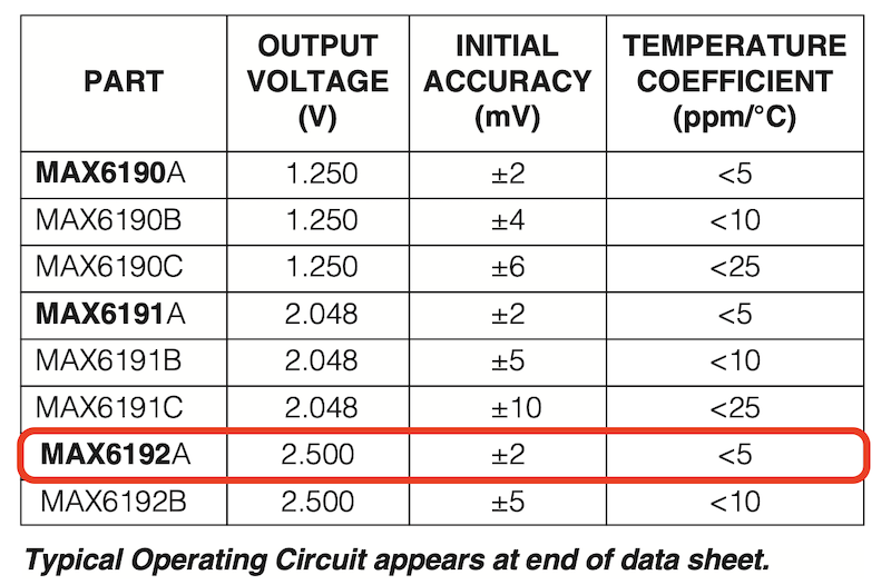
Underneath the OCXO sits a MAX6192A voltage reference (datasheet) and another jelly-bean IC.
Let’s dive deeper and figure out how it works.
The TM4313 Schematic
Here’s the PCB again, but now fully annotated:
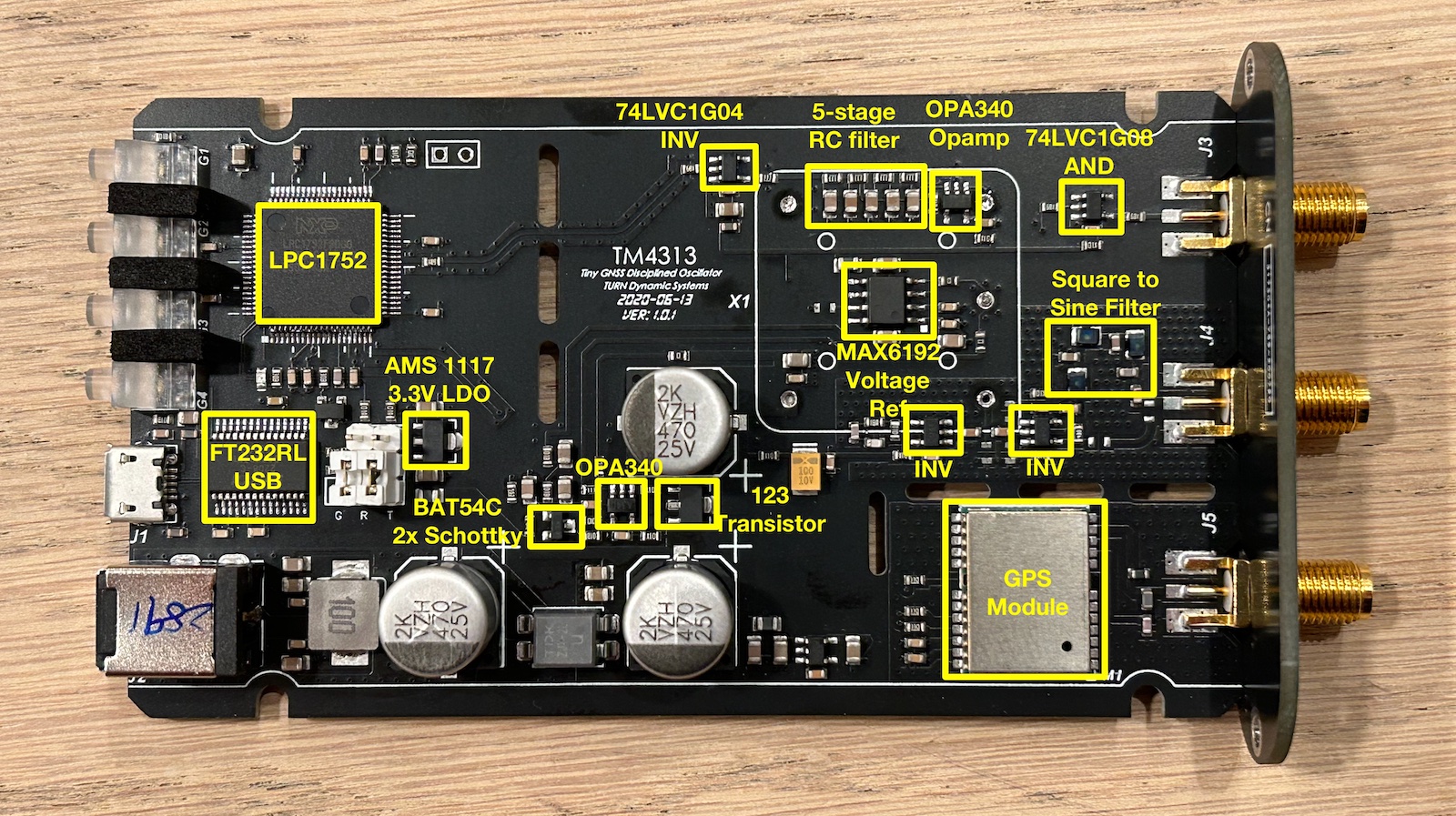 (Click to enlarge)
From this, we can recover a block diagram that is quite traditional for a GPSDO:

- The OCXO generates a 5V 10MHz square wave signal.
- One branch buffers the signal with an inverter and then sends it through an L/C low pass filter to create a 10MHz sine wave output.
- The other branch buffers the 10MHz signal as well and sends it to the microcontroller.
- The GPS unit creates a 1PPS signal that also goes to the microcontroller
- The microcontroller does its magic and generates an OCXO tuning value. It uses pulse width modulation, an R/C filter, and an opamp to create a slow but precise discrete D/A converter (DAC).
- The DAC output goes to the OCXO tuning input and the loop is closed.
Outside the main loop, there’s also the following functions:
- An FTDI FT232RL USB-serial converter can either be connected to the GPS module, that’s the default, to send standard NMEA codes for further processing by a PC, or it can connect to the serial port of the microcontroller.
- There’s a discrete 5V regulator that uses a MAX6192 voltage reference, another OPA340 opamp, and a transistor.
Frequency or Phase Lock Loop?
There are 2 ways to create GPSDO: with a frequency lock loop (FLL) or a phase locked loop (PLL).
Frequency Locked Loop
In a frequency locked loop, a controller measures the frequency of a generated signal against a reference signal, and adjust the generated signal when the value is off.
FLLs are easier to design, but they react slower when the generated frequency gets off the mark (e.g. due to external temperature changes.) That’s because it’s possible for the phase of the 2 signals to be off, but not sufficiently so that there’s a difference in measured frequency. But a major issue with FLLs is that temporary errors aren’t compensated for later: for example, if the frequency is a bit too low for a while, an FLL will fix that eventually by regulating the frequency back where it needs to be, but it will not temporarily increase for a bit to compensate it being too low earlier. This can result in long term drift.
Phase Locked Loop
In a phase locked loop, the phase between 2 signals is measured and the frequency is adjusted to keep the phase in check. A PLL will react faster to a deviation in frequency, but they are often harder to control and keep stable.
A PLL controlled GPSDO needs a phase detector between the generated and the reference signal. This almost always happens in the analog domain, with a capacitor that gets charged more or less depending on the phase difference, and an A/D converter (ADC) to read out the value.
There is no such phase detector or ADC on this PCB, so it's a good guess to assume
that the TM4313 uses frequency locked loop.
UPDATE:
It has been pointed out to me that you don’t need an analog phase phase detector, and that it can be done perfectly fine by counting the number of cycles between 1PPS pulses with a clock that’s fast enough. The LPC1752 runs internally at 100MHz2, which is high enough to do phase detection when averaging over a large amount of measurements. They might even be using linear regression for the measurement!
I soldered a wire to the GPS module 1PPS output, put it on the scope together with the stabilized 1PPS output and let things run for a whole night to check out the relationship between the two. Here is result:
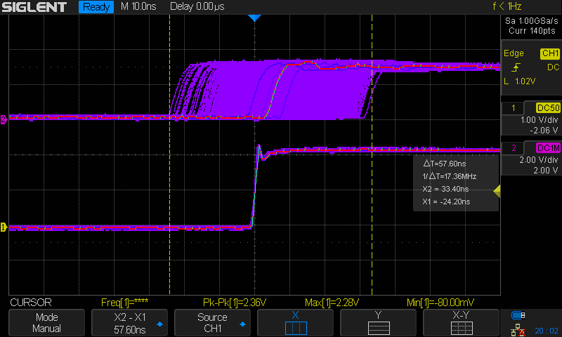
Here we see a range of 57ns, but there’s no persistent drift, so that points to a PLL.
As we shall see below, the TM4313 first works in coarse tracking mode before it switches to fine tracking. The screenshot above includes the coarse tracking, which can be expected to be less precise.
After running for a whole night, we can expect that GPSDO to have found an analog tuning value that’s pretty stable, with no need to make big adjustments. Any pulse-to-pulse jitter should be due to the limited clock speed of the GPS module internal oscillator.
So after taking the screenshot above, I cleared the screen and captured the first 10 seconds:
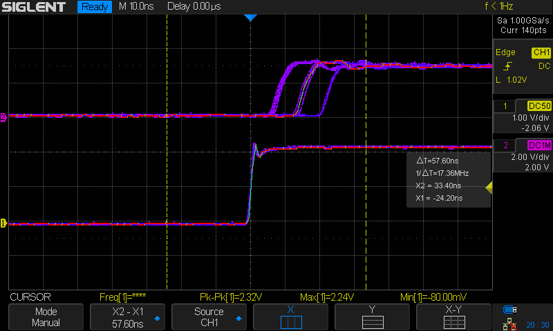
Here we can clearly see how the GPS module creates the 1PPS signal with discrete steps of around 8ns. This is similar to the popular u-blox GPS modules (and their clones!)
OCXO Temperature
I ran a quick test to check the startup behavior of the TM4313. I taped a thermocouple to the top of the OCXO, put the PCB back in the enclosure, and let it go through the motions after power up the device.
The temperature in my lab was a constant 23.3C.
| Time | Temp (C) | Comment |
|---|---|---|
| 0m00 | 23.3 | Power On |
| 0m23 | 27.1 | GNSS Lock |
| 1m00 | 31.2 | |
| 2m00 | 40.6 | |
| 3m00 | 43.8 | |
| 4m00 | 45.5 | |
| 5m00 | 45.8 | |
| 5m25 | 46.3 | Time Track |
| … | ||
| 1h | 50.4 | Steady state |
The GNSS lock time depends heavily on the position of the antenna. This time, it locked very fast, just 23 seconds, but I’ve seen it take minutes with the antenna in the same exact position.
We already know that the OCXO heater goes full blast only during the first minute. The steep part of the OCXO warming-up curve takes longer, about 2 minutes. It takes time for the heat inside the oven to warm up the outside shell. Things then slow down significantly. It takes another 3 minutes for the PLL to lock and the GPSDO to track the GPS signal.
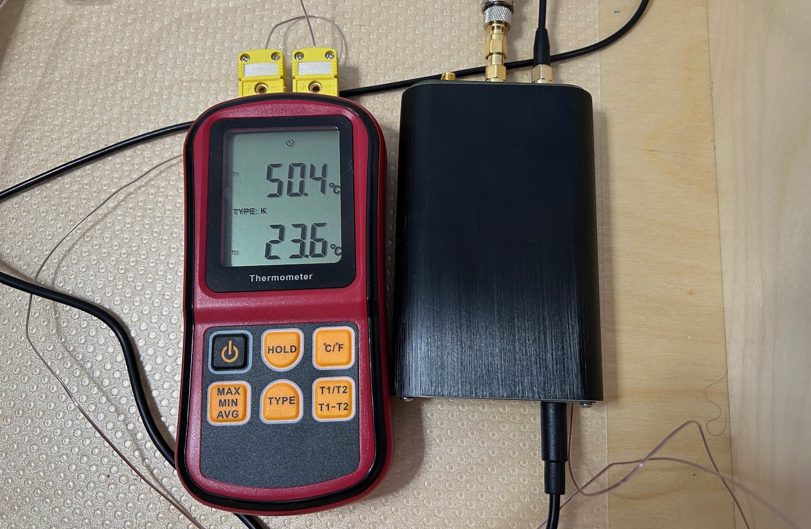
After that, the temperature continues to creep up. It take another hour before the temperature stablizes at around 50.4C. By then, the outside temperature had also increase to 23.6C. When I moved that thermocouple away from the GPSDO, the temperature dropped back down to 23.3C. I guess it was just sitting to close the GPSDO.
The Curious Case of the MAX6192 Voltage Reference
As mentioned earlier, there’s a MAX6192 voltage reference that’s squeezed between the PCB and the OXCO (without touching it!)
Why is it located there? I think it’s because the output of a voltage reference has still some amount of temperature dependency. In this case, it’s around 5ppm/C.
Since the OCXO has temperature controlled oven, the location underneath is the one with the most predictable, constant temperature.
But that doesn’t answer a more important question: why is there a voltage reference to begin with?
It’s essential to have a voltage reference in a stand-alone non-GPS controlled OCXO, because there’s no feedback mechanism to keep the output frequency in check when outside conditions change. But that’s not the case here. There are tons of GPSDO designs out there, built by hobbyists but with better specifications, yet none of them have a voltage reference.
The voltage reference in the TM4313 is used to create the stable 5V power supply that is used to power the heater inside the OCXO and the DAC opamp. I don’t have the specifications of the OC5SC25, but for most OCXOs, the sensitivy of the output frequency to the power supply is very low.
It’s surprising that one of the lowest cost commercial GPSDOs out there has an expensive component3 that isn’t really needed.
The Discrete Tuning DAC
Despite the fact that the microcontroller has a 10-bit DAC, the TM4313 uses pin P1[25] of the LPC1752 to construct a discrete DAC and control the tuning input of the OCXO. There’s a good reason for this: 10-bit is just not enough to resolution to create a tuning voltage with microvolt precision.

It’s no coincidence that this pin has PWM functionality. I couldn’t find the number of bits of the PWM controller, but even if that is also only 10-bits, you can increase the precision by dithering between different values and low pass filtering the result. 4 Using PWM to create a OCXO tuning voltage is a standard technique.
At the output of the DAC is a 5-stage low-pass R/C network that consists of a ladder of 4 33k resistors with 5 2.5uF capacitors shunted to ground in between. That should be sufficient to kill dead the ripple on a dithered PWM signal. An OPA340 opamp buffers the analog signal before it’s sent into the OCXO.
Like the voltage reference, the R/C filter and the opamp are located underneath the OCXO.
GPS Module
Immediately after plugging in the main power, the GPS module dumps the following to the serial port:
$GPTXT,01,01,02,MA=CASIC*27
$GPTXT,01,01,02,HW=ATGM332D,0001190723621*10
$GPTXT,01,01,02,IC=AT6558-5N-31-0C510800,BMDHCKJ-F1-000285*5F
$GPTXT,01,01,02,SW=URANUS5,V5.3.0.0*1D
$GPTXT,01,01,02,TB=2020-04-28,13:43:10*40
$GPTXT,01,01,02,MO=GB*77
$GPTXT,01,01,02,BS=SOC_BootLoader,V6.2.0.2*34
$GPTXT,01,01,02,FI=00856014*71
$GNGGA,,,,,,0,00,25.5,,,,,,*64
$GNGLL,,,,,,V,M*79
$GPGSA,A,1,,,,,,,,,,,,,25.5,25.5,25.5*02
$BDGSA,A,1,,,,,,,,,,,,,25.5,25.5,25.5*13
$GPGSV,1,1,00*79
$BDGSV,1,1,00*68
$GNRMC,,V,,,,,,,,,,M*4E
$GNVTG,,,,,,,,,M*2D
- ATGM332D is the name of the GPS module. It’s available on LCSC for just $2.99 if you buy just one.
- The module is based on an AT6558-5N-31 GNSS SOC from Hangzhou ZhongKe Microelectronics.
The 5N-31 version of the SOC only supports GPS and BDS, no GLONASS or Galileo.
Microcontroller instead of NMEA Serial Port
There are 2 devices with a UART on the TM4313 PC: the GPS module, which sends out standard NMEA messages, and the LPC1752 controller.
By default, the GPS is connected to the FTDI USB to serial port converter.
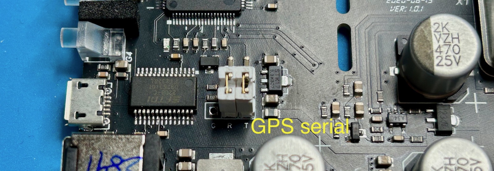
It’s not documented anywhere (there’s no documentation at all), but you can use jumpers to connect the LPC1752 to the FTDI chip instead.
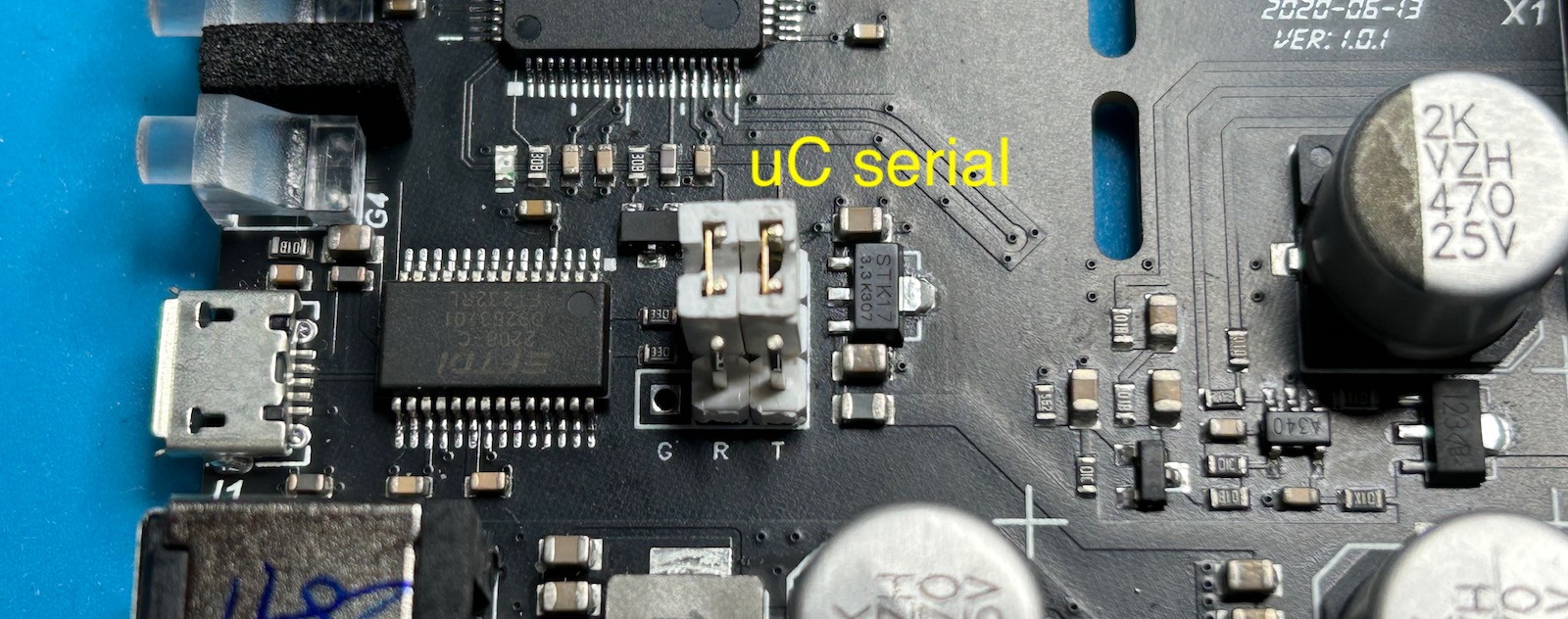
The GPS UART runs with 9600N1 and the LPC1752 with 115200N1 parameter. When I connect
the TM4313 to my Linux PC with the USB cable, it shows up as a /dev/ttyUSB0 device.
For most use cases, the NMEA data is more useful than the GPSDO internal state, but if you ever need to know whether or not the GPSDO tracking algorithm has locked the OCXO to the GPS unit, or whether the tracking is in coarse or fine mode, the information is there.
After moving the 2 jumpers and powering up the device, you’ll see the following:
-- TURN Dynamic Systems --
  TM4313 Miniature GPSDO

HV: 1.0.1
SV: 1.0.8
SD: May 14 2023, 23:45:34
SN: 25142891
SC: 100.000000MHz
AF: 19/73

Ph =    0, D =  548850, GL = 1, LOS = 0, ST =      0, AF =  19, RT = 1
Ph =    0, D =  548850, GL = 1, LOS = 0, ST =      0, AF =  19, RT = 2
Ph =    0, D =  548850, GL = 1, LOS = 0, ST =      0, AF =  19, RT = 3
...
TURN Dynamic Systems is the creator of the TM4313. They also show up at the creator of the FSA3011 frequency stability analyzer.
After some miscellaneous information, you get a bunch of columns with the internal state of the GPSDO machine. Here’s what I think it all means:
-
Ph: phase difference?
Once the GPSDO is locked, Ph typically only sees the numbers -1, 0, and 1.
-
D: ?
I think this number is related to the tuning value that is sent to the OCXO.
-
GL: GPS Loss?
This value is 1 when the GNSS LED is off. Once the GNSS signals have been acquired, the LED goes on and GL becomes 0.
-
LOS: LOck State?
This number goes from 0 to 3 while progressing through different phases of the GPSDO finite state machine (FSM).
0: power up state.
1: the FSM is some tracking state where it starts to lock the OCXO onto the 1PSS signal. It stays there until an ‘STB’ number converges to 0.
2: the FSM is in another tracking state. It stays there until a value
cKshows up as being very small.3: Tracking state. The OCXO is locked onto the 1PPS signal.
-
ST: State Time?
This number counts the number seconds the FSM has been in the current LOS state.
-
AF: Adjustment something?
A parameter that indicates whether or not the GPSDO tracking algorithm is in a coarse or fine tracking state. Initially, it has a number of 19 and the value of
Djumps around quite a bit. After while, this number jumps to 73 andDvalue changes are more subtle.When you tap onto the OCXO while it’s in the 73 state, it will immediately jump back to 19.
-
RT: Run Time
Starts at 0 at power up. Increases continuously every second.
Here’s an example of the GPSDO going through different states:
Power On
Ph =    0, D =  548850, GL = 1, LOS = 0, ST =      0, AF =  19, RT = 1
Ph =    0, D =  548850, GL = 1, LOS = 0, ST =      0, AF =  19, RT = 2
Ph =    0, D =  548850, GL = 1, LOS = 0, ST =      0, AF =  19, RT = 3
Ph =    0, D =  548850, GL = 1, LOS = 0, ST =      0, AF =  19, RT = 4
Ph =    0, D =  548850, GL = 1, LOS = 0, ST =      0, AF =  19, RT = 5
...
GPS Lock
The GNSS LED goes on. GL goes low. Notice how the Ph value starts changing right away.
...
Ph =    0, D =  548850, GL = 1, LOS = 0, ST =      0, AF =  19, RT = 40
Ph =    0, D =  548850, GL = 1, LOS = 0, ST =      0, AF =  19, RT = 41
Ph =    0, D =  548850, GL = 1, LOS = 0, ST =      0, AF =  19, RT = 42
Ph =    0, D =  548850, GL = 1, LOS = 0, ST =      0, AF =  19, RT = 43
Ph =    0, D =  548850, GL = 0, LOS = 0, ST =      0, AF =  19, RT = 44
Ph =   -5, D =  548850, GL = 0, LOS = 0, ST =      1, AF =  19, RT = 45
Ph =   -9, D =  548850, GL = 0, LOS = 0, ST =      2, AF =  19, RT = 46
Ph =  -12, D =  548850, GL = 0, LOS = 0, ST =      3, AF =  19, RT = 47
...
LOS changes from 0 to 1
...
Ph =   84, D =  548850, GL = 0, LOS = 0, ST =     57, AF =  19, RT = 101
Ph =   84, D =  548850, GL = 0, LOS = 0, ST =     58, AF =  19, RT = 102
Ph =   86, D =  548850, GL = 0, LOS = 0, ST =     59, AF =  19, RT = 103
Ph =   86, D =  548850, GL = 0, LOS = 0, ST =     60, AF =  19, RT = 104
Ph =    0, D =  548850, GL = 0, LOS = 1, ST =      0, AF =  19, RT = 105
Ph =    2, D =  548850, GL = 0, LOS = 1, ST =      1, AF =  19, RT = 106
Ph =    2, D =  548850, GL = 0, LOS = 1, ST =      2, AF =  19, RT = 107
Ph =    4, D =  548850, GL = 0, LOS = 1, ST =      3, AF =  19, RT = 108
...
LOS changes from 1 to 2
Initally during state 1, the same columns are sent to the UART, but at the end, an additional STB field is added that converges to 0. Once it’s below a certain threshold, the GPSDO switches to state 2.
...
Ph =   29, D =  548850, GL = 0, LOS = 1, ST =     56, AF =  19, RT = 161
Ph =   29, D =  548850, GL = 0, LOS = 1, ST =     57, AF =  19, RT = 162
Ph =   29, D =  548850, GL = 0, LOS = 1, ST =     58, AF =  19, RT = 163
Ph =   29, D =  548850, GL = 0, LOS = 1, ST =     59, AF =  19, STB = -2.57500E-9, RT = 164
Ph =   29, D =  548850, GL = 0, LOS = 1, ST =     60, AF =  19, STB = -2.52500E-9, RT = 165
Ph =   30, D =  548850, GL = 0, LOS = 1, ST =     61, AF =  19, STB = -2.42500E-9, RT = 166
Ph =   29, D =  548850, GL = 0, LOS = 1, ST =     62, AF =  19, STB = -2.35000E-9, RT = 167
Ph =   29, D =  548850, GL = 0, LOS = 1, ST =     63, AF =  19, STB = -2.32500E-9, RT = 168
Ph =   31, D =  548850, GL = 0, LOS = 1, ST =     64, AF =  19, STB = -2.25000E-9, RT = 169
Ph =   30, D =  548850, GL = 0, LOS = 1, ST =     65, AF =  19, STB = -2.15000E-9, RT = 170
Ph =   30, D =  548850, GL = 0, LOS = 1, ST =     66, AF =  19, STB = -2.07500E-9, RT = 171
Ph =   32, D =  548850, GL = 0, LOS = 1, ST =     67, AF =  19, STB = -2.05000E-9, RT = 172
Ph =   31, D =  548850, GL = 0, LOS = 1, ST =     68, AF =  19, STB = -1.95000E-9, RT = 173
Ph =   31, D =  548850, GL = 0, LOS = 1, ST =     69, AF =  19, STB = -1.75000E-9, RT = 174
Ph =   32, D =  548850, GL = 0, LOS = 1, ST =     70, AF =  19, STB = -1.72500E-9, RT = 175
Ph =   31, D =  548850, GL = 0, LOS = 1, ST =     71, AF =  19, STB = -1.57500E-9, RT = 176
Ph =   32, D =  548850, GL = 0, LOS = 1, ST =     72, AF =  19, STB = -1.50000E-9, RT = 177
Ph =   33, D =  548850, GL = 0, LOS = 1, ST =     73, AF =  19, STB = -1.40000E-9, RT = 178
Ph =   33, D =  548850, GL = 0, LOS = 1, ST =     74, AF =  19, STB = -1.27500E-9, RT = 179
Ph =   32, D =  548850, GL = 0, LOS = 1, ST =     75, AF =  19, STB = -1.25000E-9, RT = 180
Ph =   33, D =  548850, GL = 0, LOS = 1, ST =     76, AF =  19, STB = -1.20000E-9, RT = 181
Ph =   34, D =  548850, GL = 0, LOS = 1, ST =     77, AF =  19, STB = -1.17500E-9, RT = 182
Ph =   33, D =  548850, GL = 0, LOS = 1, ST =     78, AF =  19, STB = -1.10000E-9, RT = 183
Ph =   33, D =  548850, GL = 0, LOS = 1, ST =     79, AF =  19, STB = -0.95000E-9, RT = 184
Ph =   34, D =  548850, GL = 0, LOS = 1, ST =     80, AF =  19, STB = -0.85000E-9, RT = 185
Ph =   33, D =  548850, GL = 0, LOS = 1, ST =     81, AF =  19, STB = -0.82500E-9, RT = 186
Ph =   33, D =  548850, GL = 0, LOS = 1, ST =     82, AF =  19, STB = -0.72500E-9, RT = 187
Ph =   34, D =  548850, GL = 0, LOS = 1, ST =     83, AF =  19, STB = -0.60000E-9, RT = 188
Ph =    0, D =  548542, GL = 0, LOS = 2, ST =      0, AF =  19, RT = 189
Ph =    1, D =  528542, GL = 0, LOS = 2, ST =      0, AF =  19, RT = 190
Ph =   -2, D =  528542, GL = 0, LOS = 2, ST =      0, AF =  19, RT = 191
...
LOS changes from 2 to 3, Track LED goes on
Close to the end of state 2, a single ‘cK’ field is printed out with some low number. Once this happens, the FSM soon switches to state 3 and the Track LED switches on. At that point, the Ph value starts fluctuating between values that are usuall -1, 0, and 1.
The D values start changing with each tick, but the difference between consecutive
numbers is quite high, usually between 10 and 15.
...
Ph =  -43, D =  568542, GL = 0, LOS = 2, ST =     37, AF =  19, RT = 246
Ph =  -37, D =  568542, GL = 0, LOS = 2, ST =     38, AF =  19, RT = 247
Ph =  -30, D =  568542, GL = 0, LOS = 2, ST =     39, AF =  19, RT = 248
Ph =  -23, D =  568542, GL = 0, LOS = 2, ST =     40, AF =  19, RT = 249
Ph =  -15, D =  568542, GL = 0, LOS = 2, ST =     41, AF =  19, cK = 0.003375E-9/LSB, RT = 250
Ph =  -10, D =  548394, GL = 0, LOS = 2, ST =     42, AF =  19, RT = 251
Ph =   -7, D =  548394, GL = 0, LOS = 2, ST =     43, AF =  19, RT = 252
Ph =   -7, D =  548394, GL = 0, LOS = 2, ST =     44, AF =  19, RT = 253
Ph =   -6, D =  548394, GL = 0, LOS = 2, ST =     45, AF =  19, RT = 254
Ph =   -6, D =  548394, GL = 0, LOS = 2, ST =     46, AF =  19, RT = 255
Ph =   -6, D =  548394, GL = 0, LOS = 2, ST =     47, AF =  19, RT = 256
Ph =   -6, D =  548394, GL = 0, LOS = 2, ST =     48, AF =  19, RT = 257
Ph =   -6, D =  548394, GL = 0, LOS = 2, ST =     49, AF =  19, RT = 258
Ph =   -6, D =  548394, GL = 0, LOS = 2, ST =     50, AF =  19, RT = 259
Ph =   -5, D =  548394, GL = 0, LOS = 2, ST =     51, AF =  19, RT = 260
Ph =    0, D =  548394, GL = 0, LOS = 3, ST =      0, AF =  19, RT = 261
Ph =    0, D =  548394, GL = 0, LOS = 3, ST =      1, AF =  19, RT = 262
Ph =    0, D =  548394, GL = 0, LOS = 3, ST =      2, AF =  19, RT = 263
Ph =    0, D =  548394, GL = 0, LOS = 3, ST =      3, AF =  19, RT = 264
Ph =   -1, D =  548394, GL = 0, LOS = 3, ST =      4, AF =  19, RT = 265
Ph =   -1, D =  548433, GL = 0, LOS = 3, ST =      5, AF =  19, RT = 266
Ph =   -1, D =  548464, GL = 0, LOS = 3, ST =      6, AF =  19, RT = 267
Ph =    0, D =  548490, GL = 0, LOS = 3, ST =      7, AF =  19, RT = 268
Ph =    0, D =  548490, GL = 0, LOS = 3, ST =      8, AF =  19, RT = 269
Ph =   -1, D =  548490, GL = 0, LOS = 3, ST =      9, AF =  19, RT = 270
Ph =   -1, D =  548508, GL = 0, LOS = 3, ST =     10, AF =  19, RT = 271
Ph =   -1, D =  548523, GL = 0, LOS = 3, ST =     11, AF =  19, RT = 272
Ph =   -1, D =  548537, GL = 0, LOS = 3, ST =     12, AF =  19, RT = 273
Ph =   -1, D =  548550, GL = 0, LOS = 3, ST =     13, AF =  19, RT = 274
Ph =   -1, D =  548562, GL = 0, LOS = 3, ST =     14, AF =  19, RT = 275
...
Switch from coarse to fine mode
1260 seconds after powering up, AF changes from 19 to 73. The D value changes
are now much smaller. The difference is usually less than 5.
...
Ph =   -1, D =  548481, GL = 0, LOS = 3, ST =    996, AF =  19, RT = 1257
Ph =   -1, D =  548497, GL = 0, LOS = 3, ST =    997, AF =  19, RT = 1258
Ph =   -1, D =  548505, GL = 0, LOS = 3, ST =    998, AF =  19, RT = 1259
Ph =   -1, D =  548520, GL = 0, LOS = 3, ST =    999, AF =  73, RT = 1260
Ph =    0, D =  548520, GL = 0, LOS = 3, ST =   1000, AF =  73, RT = 1261
Ph =    1, D =  548520, GL = 0, LOS = 3, ST =   1001, AF =  73, RT = 1262
Ph =    0, D =  548518, GL = 0, LOS = 3, ST =   1002, AF =  73, RT = 1263
Ph =    0, D =  548520, GL = 0, LOS = 3, ST =   1003, AF =  73, RT = 1264
Ph =    0, D =  548523, GL = 0, LOS = 3, ST =   1004, AF =  73, RT = 1265
Ph =    0, D =  548525, GL = 0, LOS = 3, ST =   1005, AF =  73, RT = 1266
Ph =    0, D =  548527, GL = 0, LOS = 3, ST =   1006, AF =  73, RT = 1267
Ph =    0, D =  548529, GL = 0, LOS = 3, ST =   1007, AF =  73, RT = 1268
Ph =    0, D =  548531, GL = 0, LOS = 3, ST =   1008, AF =  73, RT = 1269
Ph =    0, D =  548531, GL = 0, LOS = 3, ST =   1009, AF =  73, RT = 1270
Ph =    0, D =  548531, GL = 0, LOS = 3, ST =   1010, AF =  73, RT = 1271
Ph =    1, D =  548531, GL = 0, LOS = 3, ST =   1011, AF =  73, RT = 1272
Ph =    1, D =  548527, GL = 0, LOS = 3, ST =   1012, AF =  73, RT = 1273
Ph =    0, D =  548523, GL = 0, LOS = 3, ST =   1013, AF =  73, RT = 1274
Ph =    1, D =  548523, GL = 0, LOS = 3, ST =   1014, AF =  73, RT = 1275
Ph =    0, D =  548519, GL = 0, LOS = 3, ST =   1015, AF =  73, RT = 1276
...
Tapping on the OCXO makes the GPSDO switch back from fine to coarse mode
OCXO don’t like physical abuse!
...
Ph =    0, D =  548548, GL = 0, LOS = 3, ST =  12316, AF =  73, RT = 12577
Ph =    0, D =  548546, GL = 0, LOS = 3, ST =  12317, AF =  73, RT = 12578
Ph =    1, D =  548546, GL = 0, LOS = 3, ST =  12318, AF =  73, RT = 12579
Ph =    2, D =  548544, GL = 0, LOS = 3, ST =  12319, AF =  73, RT = 12580
Ph =    2, D =  548538, GL = 0, LOS = 3, ST =  12320, AF =  73, RT = 12581
Ph =    2, D =  548534, GL = 0, LOS = 3, ST =  12321, AF =  73, RT = 12582
Ph =    2, D =  548529, GL = 0, LOS = 3, ST =  12322, AF =  73, RT = 12583
Ph =    3, D =  548525, GL = 0, LOS = 3, ST =  12323, AF =  19, RT = 12584
Ph =    3, D =  548525, GL = 0, LOS = 3, ST =  12324, AF =  19, RT = 12585
Ph =    3, D =  548510, GL = 0, LOS = 3, ST =  12325, AF =  19, RT = 12586
Ph =    3, D =  548478, GL = 0, LOS = 3, ST =  12326, AF =  19, RT = 12587
Ph =    3, D =  548447, GL = 0, LOS = 3, ST =  12327, AF =  19, RT = 12588
Ph =    4, D =  548416, GL = 0, LOS = 3, ST =  12328, AF =  19, RT = 12589
Ph =    3, D =  548384, GL = 0, LOS = 3, ST =  12329, AF =  19, RT = 12590
Ph =    4, D =  548360, GL = 0, LOS = 3, ST =  12330, AF =  19, RT = 12591
...
GPSDO Performance
The most important aspect of a GPSDO its performance: how stable is the output frequency.
I currently don’t have the setup and expertise yet to evaluate that. For that, I’ll just refer to the earlier mentioned report: Comparison of Inexpensive 10 MHz GNSS Disciplined Oscillators.
Conclusion
Building your own GPSDO is a bit of rite of passage for many hobbyists, and something I’ve been researching for quite a bit. But with commercial GPSDOs being available for less than $100, it’s tempting to just buy one.
The TM4313 seems good enough to a reference clock for my frequency counters, spectrum analyzer, and signal generators, or to calibrate the OCXOs that are living inside them.
Its design is also simple enough for a beginner to get a decent understanding.
For now, my desire to get improve the accuracy of my measurements has been met, but we’ll see how long it takes before I want it to the next level.
References
- TM4313 Datasheet
- Bliley - Crystal Oscillators: The Beginner’s Guide (OCXO, TCXO, VCXO, & Clocks)
- Comparison of Inexpensive 10 MHz GNSS Disciplined Oscillators - W.D. Reeve
- A high precision 10MHz GPS disciplined oscillator (GPSDO)