Tektronix TDS 684B Oscilloscope Button Swap
Introduction
I recently bought a TDS 684B for cheap at a government auction. With 1 GHz BW and 5 Gsps sample rate, it can be used for those cases where my 350 MHz/2Gsps Siglent 2304X runs out of steam.
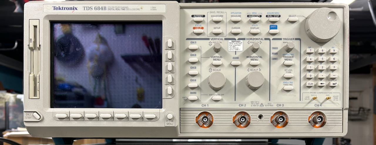
It only had one issue: one of the rotary knobs on the front panel had erratic behavior. Not completely broken, but in certain positions the behavior was all over the place.
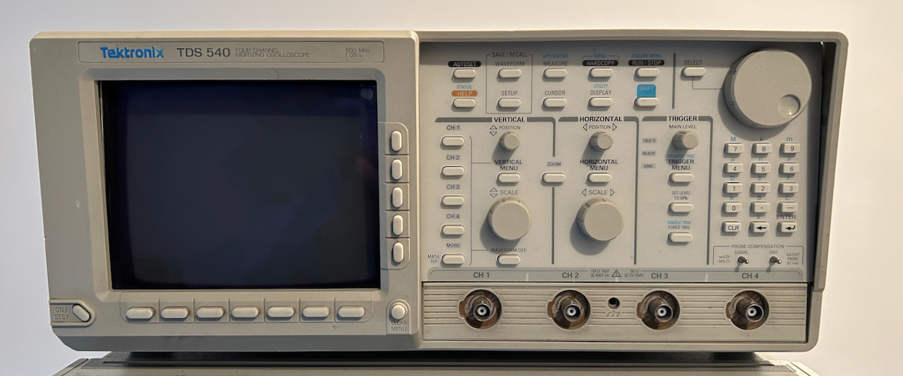
I already had a TDS 540 oscilloscope that has been gathering dust for years, with a fully working front panel that looks identical to the one of the TDS 684B.
The internal connectors are the same too, and the PCB is nearly the same as well, so I first tried swapping those panels, but while it worked it little bit, some buttons didn’t work at all: the front panels of a TDS 684B and a TDS 540 are not compatible!
The rotary encoders are custom made for Tektronix and can’t be bought individually. Since I didn’t use the TDS 540, I decided to swap the individual rotary encoders instead. That worked!
In this blog post, I go through the steps of this simple repair.
Removing the panels
The front panel disassembly instructions can be found in the TDS 520B, 540B, 620B, TDS 644B, TDS 680B, TDS 684B, TDS 724A, TDS 744A, & TDS 784A Digitizing Oscilloscope Service Manual (phew!) but they apply to all scopes with that kind of look.
I find pictures easier to work off than technical drawings. In this case, the procedure is really simple.
Trim Ring Removal
The first step is to remove the so-called trim ring. This is the part that goes around the whole front. It also contains the buttons that surround the screen.
The trim ring clicks in place at the top and the bottom. I found it easiest to insert your fingers between the trim ring and the case at the top, pull the plastic up and then move the top of the trim ring forward.
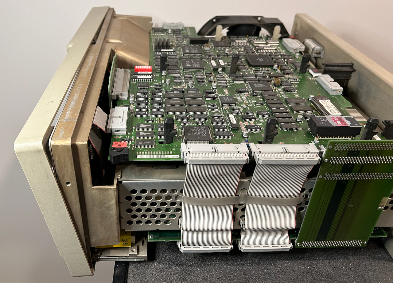
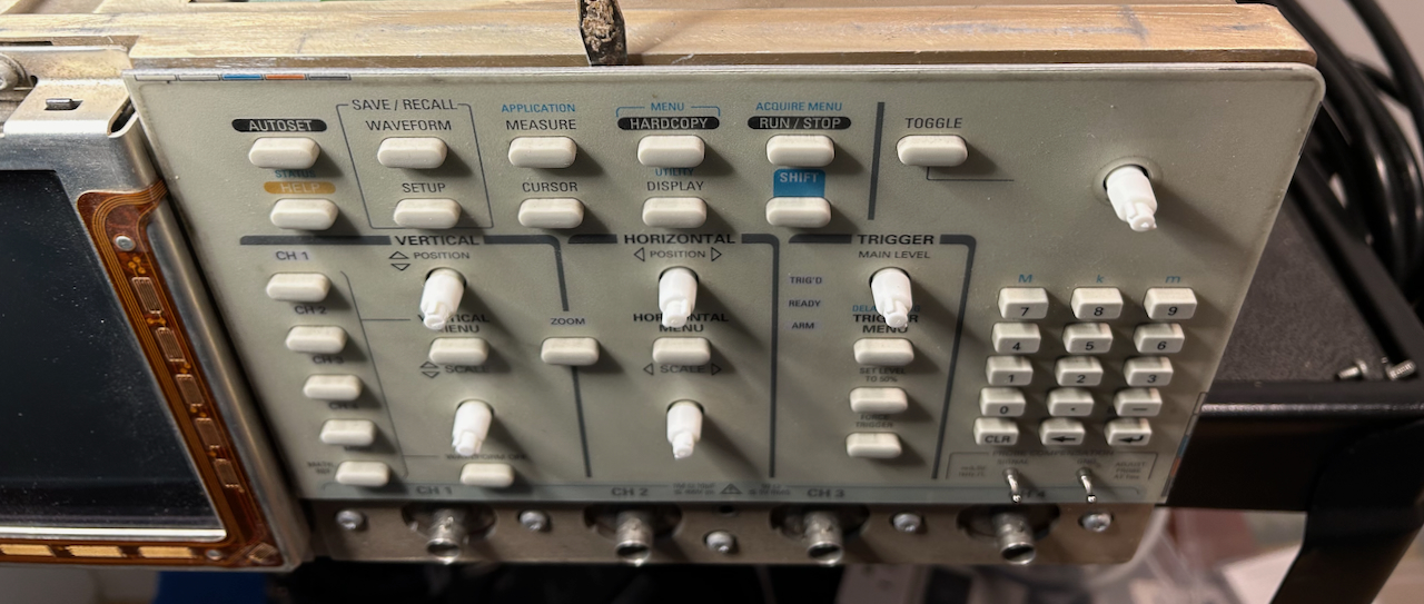
You can see how that looks in the image above. And here’s how that looks from the side. In this picture, the main enclosure is removed as well, but that’s not necessary for this repair!
Once the top of the trim ring is loose, you can pull off the top entirely and the bottom will follow.
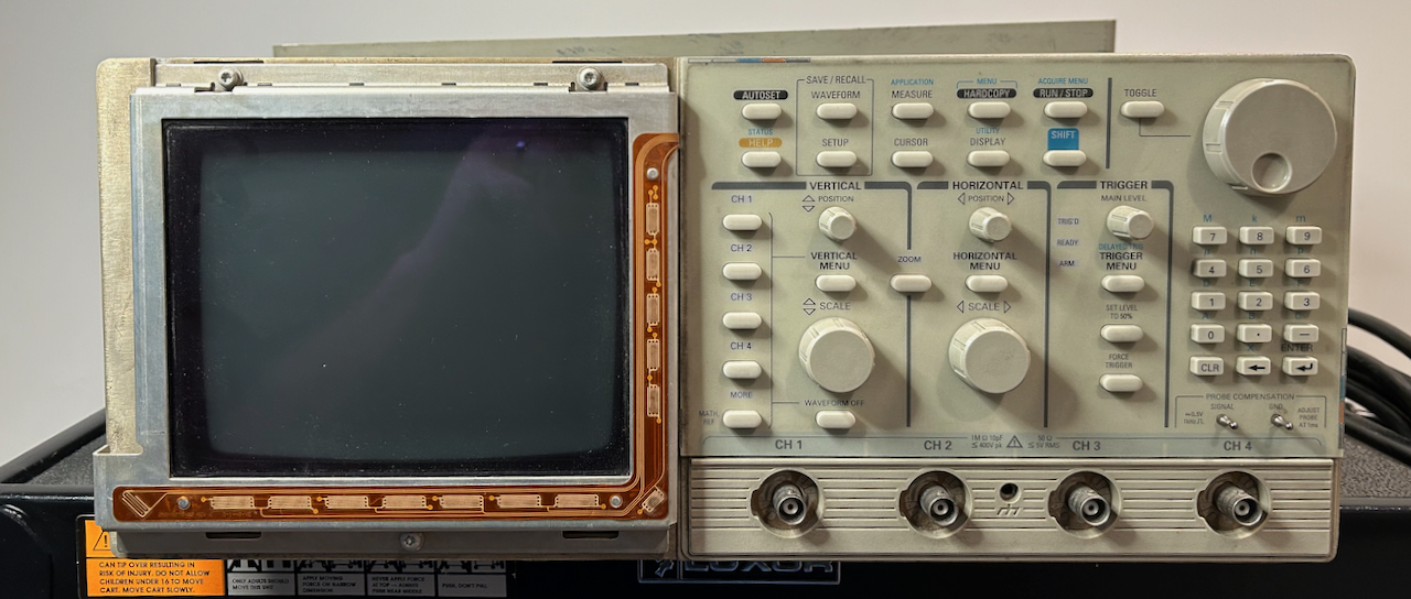
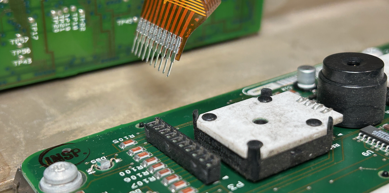
You’ll now see an orange flex cable around the screen that’s used for the screen buttons.
Knob Removal
Now is a good time to remove the knobs from the front panel, but you can also do this later. You can bypass this step entirely if you’re simply replacing a full front panel assembly without swapping out individual knobs.
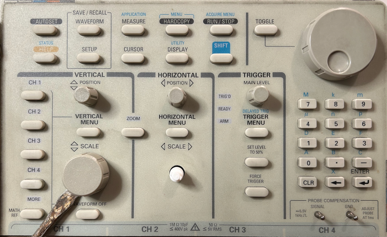
5 of the knobs, the 2 larger ones at the bottom row and the 3 smaller ones in the middle, will snap off easily when you place a screwdriver underneath them and then twist it a little bit.
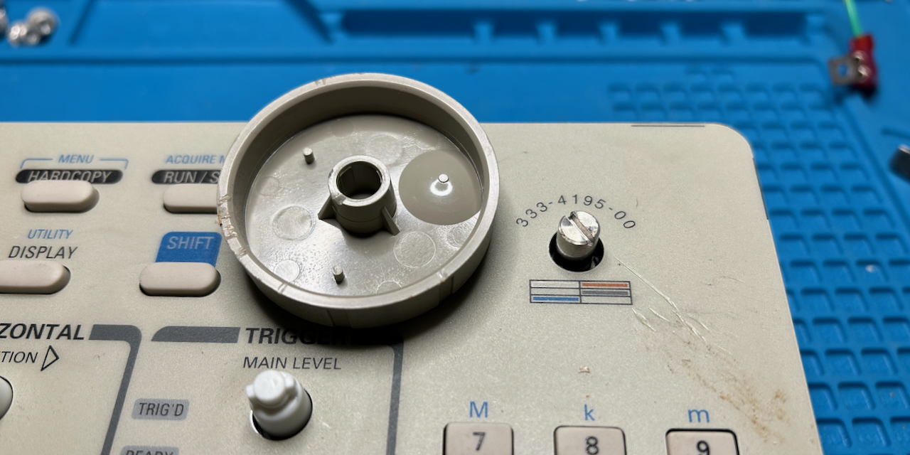
The knob at the top right is different: on the TDS 540, it uses the same click system and it came off the same way. However, on the TDS 684B, the knob was attached with friction instead of click system. Instead of a single twist with the screwdriver, I had to remove it by pulling hard to the knob until it slid off.
Here’s how that top-right knob looks like when it’s removed from the shaft:
Front Panel Assembly Removal
You can now remove the front panel assembly. It’s not screwed down, but simply squeezed into its rectangular enclosure. Use a screw driver to remove it from the enclosure. Be careful and don’t drop it, because there’s a fragile flex connector in the back that could break!
Disconnect the connectors
There are 2 connectors between the chassis and the front assembly: one big ribbon cable with a typical IDC connector that can easily be unplugged, and one fragile flex cable and connector. On the TDS 684B, there was also an additional grounding wire which was lacking on the TDS 540.
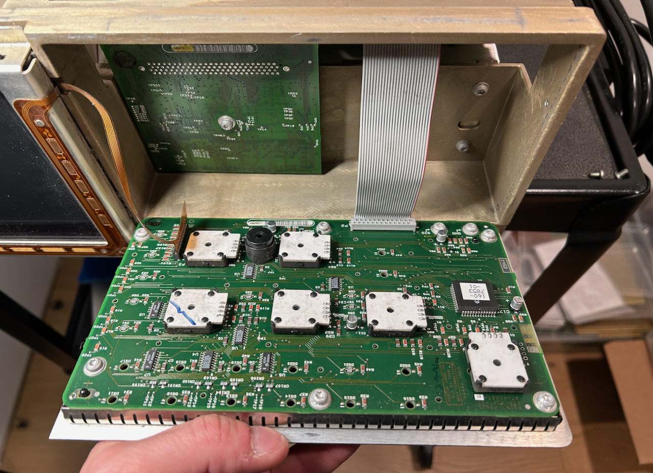
Disconnecting a flex cable is often stressful, but in this case, it came out quite easily. During reassembly, it will plug in nicely too.
The front assembly is now completely loose.
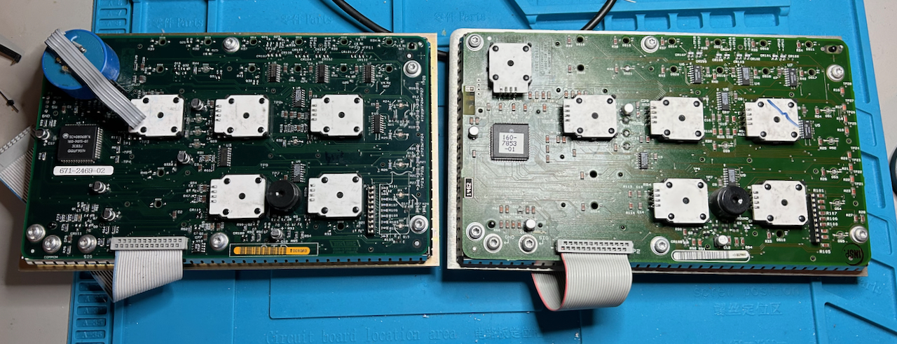
Two panels side by side
Here are the two front assemblies. The TDS 684B one is on the left, the TDS 540 is on the right. They are slightly different, especially the top right, now top left, rotary encoder, and they are not compatible.
Swapping a Rotary Encoder
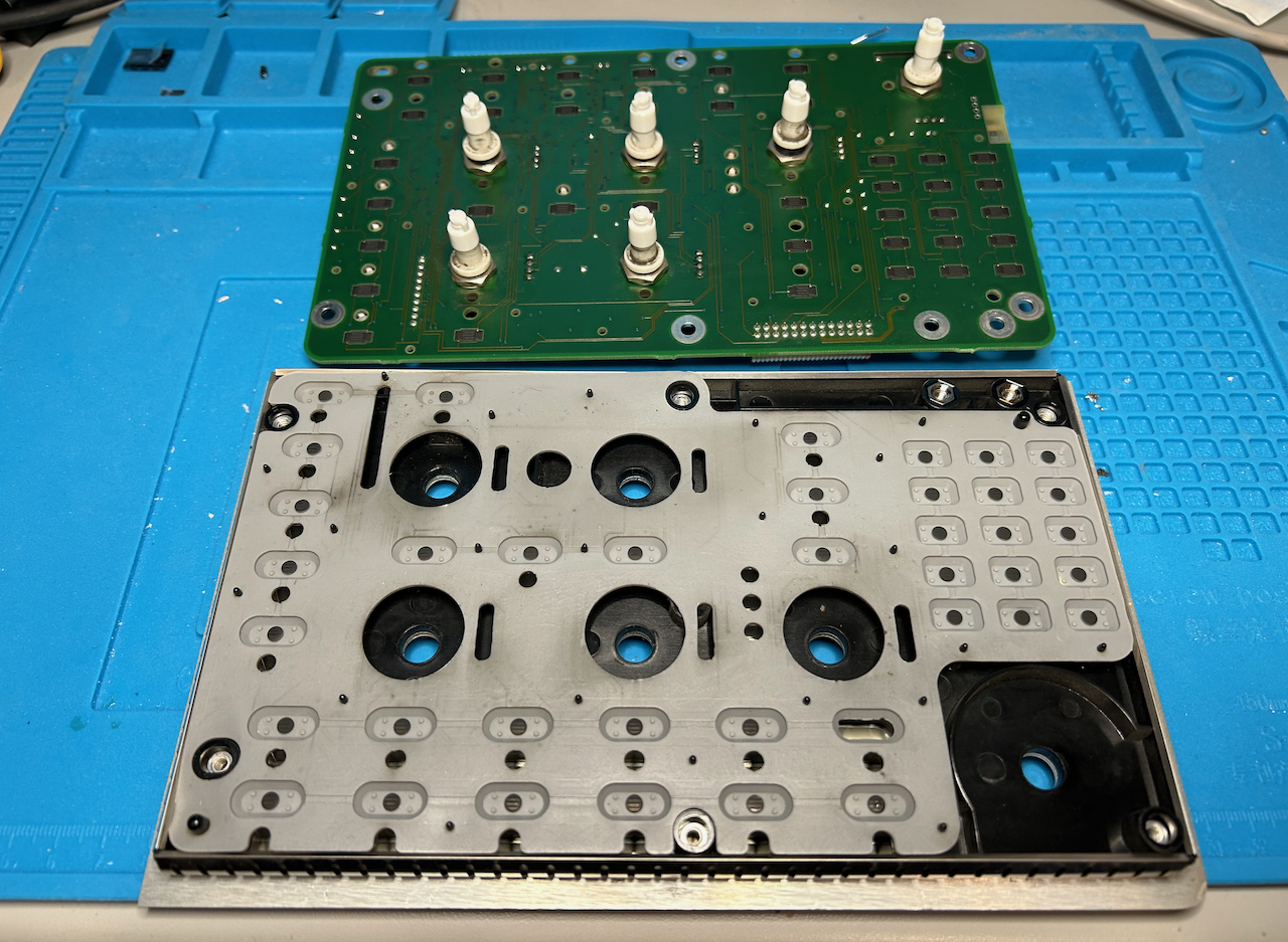
Front assembly separation
In my case, one of the bottom row rotary encoders was broken. To swap them, I first removed the PCB from the front panel. This is why I removed the knobs earlier.
There are 8 screws. Once these are gone, you can remove the PCB from the front panel.
Rotary encoder removal
Each knob has a nut and a washer. Remove the one for the knob that you need to fix.
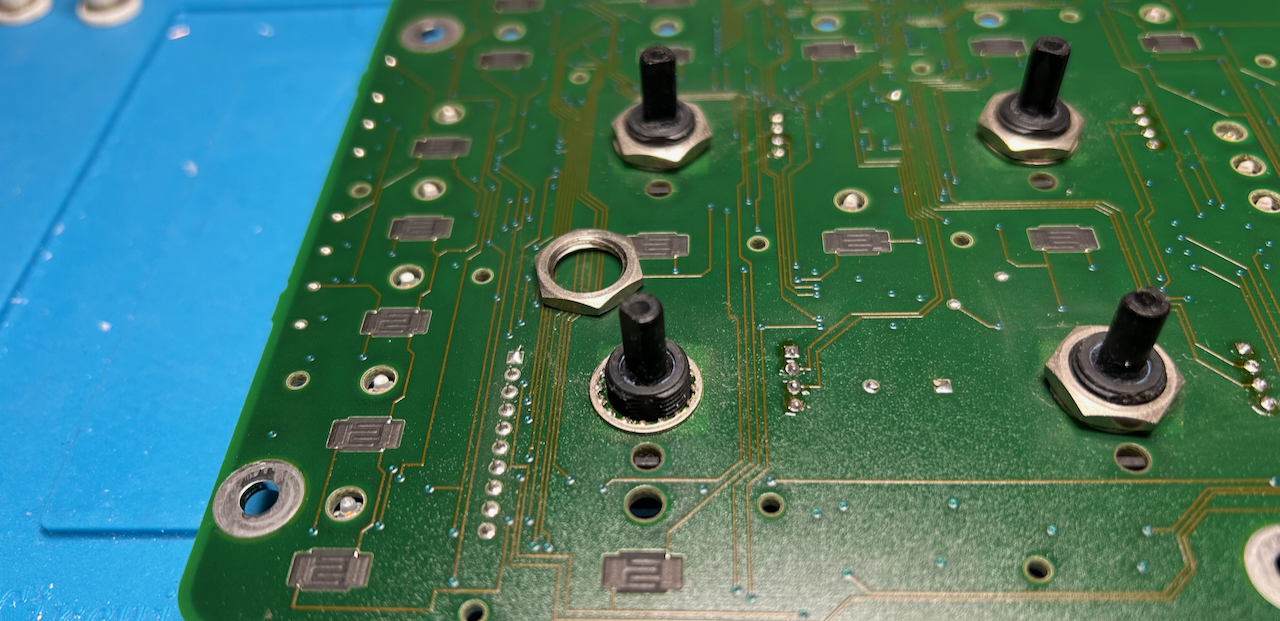
You can now remove the failing rotary encoder from one board and the replacement one from the other board. I tried to do this with a hot air station but got nowhere and I was afraid of cooking the PCB. It’s much easier to just cut them loose!
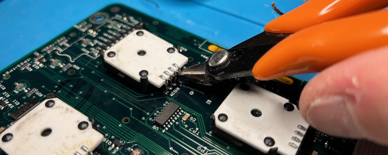
When you do this, make sure that you cut the 4 leads as close to the PCB as possible. That will make it so much easier to solder them back after swapping.
Resoldering rotary encoder
Resoldering a rotary encoder after swapping is a bit tricky and it doesn’t look that great, but it worked.
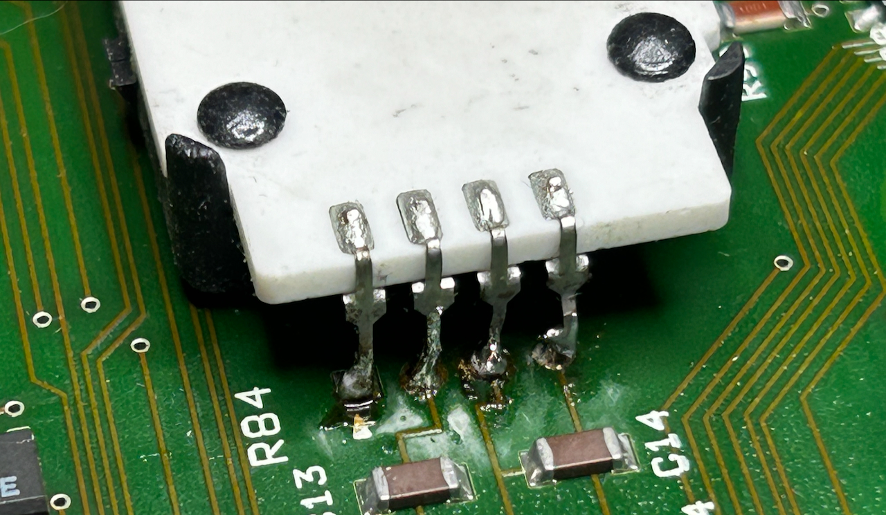
The surgery is done.
Putting it all back together
Just follow the steps in reverse to put the oscilloscopes back together.
End Result
The buttons of my TDS 684B work fine now! Total repair time from start to finish: 30min. It took longer to write it all down.
Since I still want to sell the TDS 540, I later fixed that one by buying a TDS 540A front assembly from eBay, and doing another rotary encoder swap.