Symmetricom 58532A GPS Antenna Supply Voltage Mod
- The Symmetricom 58532A
- Opening up the 58532A
- Voltage Regulation
- Result
- What about the other 58532A variant?
- References
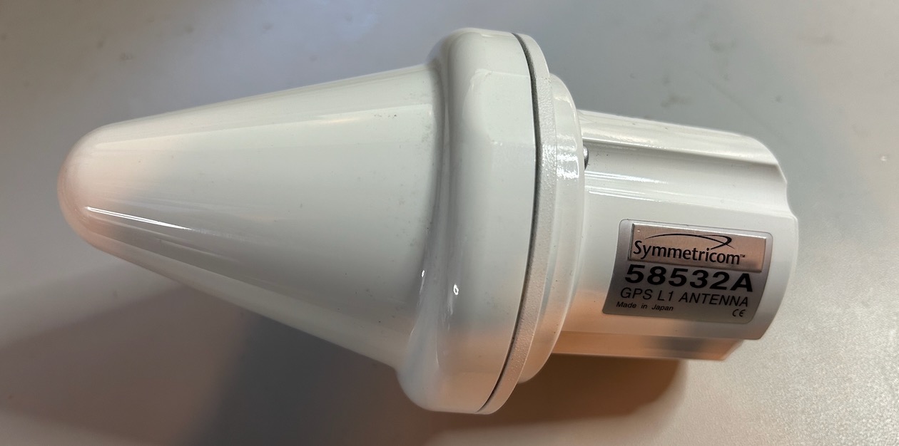
The Symmetricom 58532A
As part of a package deal, I got my hands on a Symmetricom 58532A L1 GPS antenna.
Microchip, which acquired Symmetricom in 2013, doesn’t seem to have antennas in its product line anymore, but the data sheet is still available on their website. There are also some references to an HP 58532A, but it’s not clear whether the antenna started out as an HP or a Symmetricom design.
Like all modern GPS antennas large and small, the 58532A is an active device: the signal is not only picked up at the antenna, but there’s also a filter and an amplifier before the signal is sent to the cable.
The data sheet has the following frequency response graph:
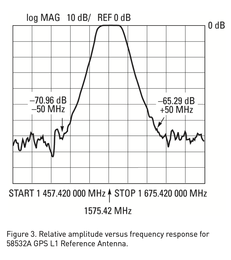
The pass band filter is centered around 1575MHz with a width of 20 MHz which gives it a range from 1565MHz to 1585MHz. Europe’s Galileo and China’s BeiDou occupy the same frequency band, but Glonass, the Russian GPS equivalent sits at 1598MHz to 1604MHz.
The full electrical specifications are in the table below:
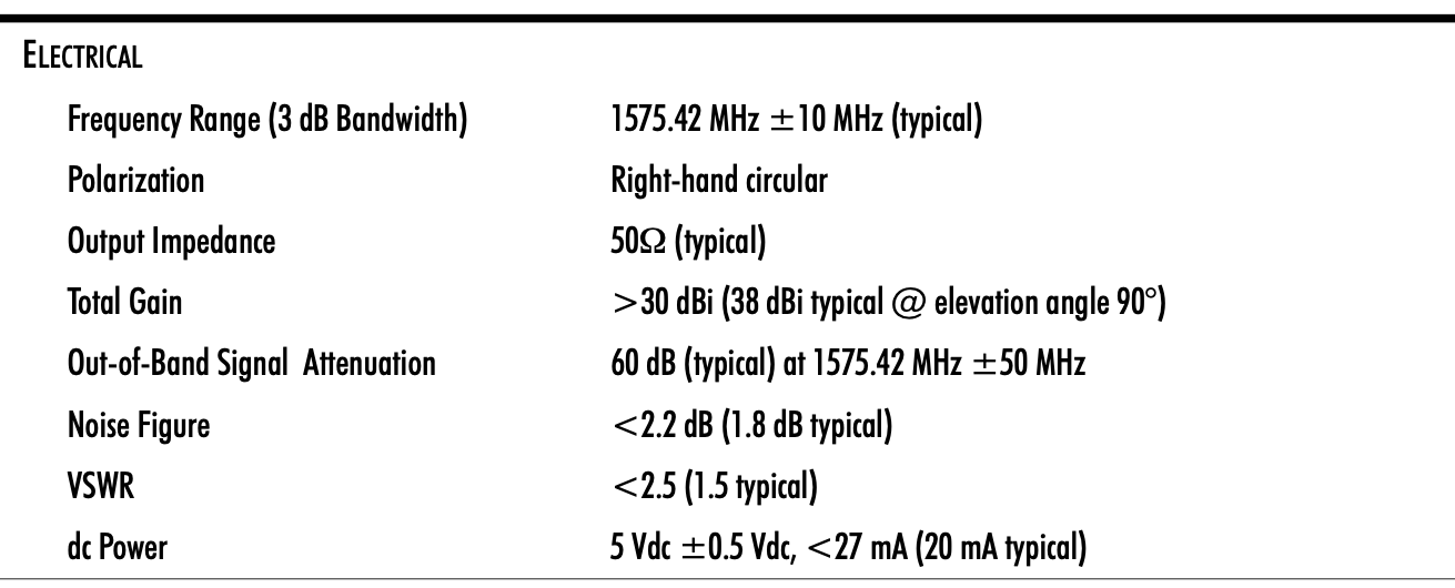
Antenna Gain
The specifcation shows a total gain that is larger than 30dBi, but dBi is also used to compare a given passive antenna against an isotropic passive antenna, so I don’t know how much of the 30dB gain is due to the amplification, and how much is due to the physical shape of antenna.
 Click to enlarge
There are multiple PCB variants of the 58532A. The one above, not mine, uses an NE3608 low noise amplifier (LNA) with a typical gain of 14dB, and two NE662M04/2SC5508 LNAs with a typical gain of 16dB. The total of that is 46dB, but I assume that some of the gain is lost due to the band pass filter. The LNAs are powered by a low drop-out voltage regulator (LDO).
My version of the PCB has different components. It also uses 3 LNAs, but I wasn’t able to identify them, and it lacks an LDO.
DC power
The topic of this blog post deals with the last line of the specification: DC power.
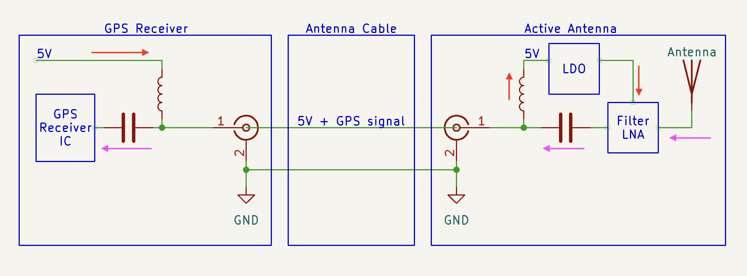
Since the antenna contains active elements, it needs to be supplied with power. Instead of a separate wire, the power is supplied through the antenna wire itself. The GPS receiver inserts a DC voltage into the antenna cable, and the antenna extacts the DC voltage on its side to power its components.
 Click to enlarge
The circuit is straightforward. The DC component, traveling from left to right, is blocked by capacitors but passes through the inductors, and the high-frequency GPS signal, going from right to left, passes through capacitors but is blocked by inductors.
Almost all GPS receivers supply a voltage of 3.3V or 5V on their antenna connector. My TM4313 GPSDO is a good example: you can measure 3.3V between the center pin of the SMA connector and the ground.
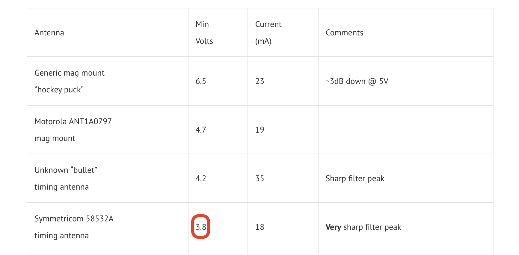
The Symmetricom 58532A specification requires a 5V supply, but mine works fine with the 3.3V of the TM4313. That’s not true for all 58532A variants though, others have a measured a minimum required voltage of 3.8V:
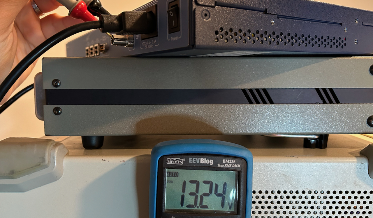
But somebody had to be contrarian and create GPS receivers that drive 12V into the antenna. That company was… Symmetricom! Their older gear was 5V, but for whatever reason they switched to 12V later on. And indeed, one of my Symmetricom devices is still 5V, but two others are 12V, including this SyncServer S200, with a voltage that is even slightly higher:
I mistakenly thought that the 58532A was 12V compatible, so when I connected it to the S200, it raised an alarm about a shorted antenna connection. Oops!
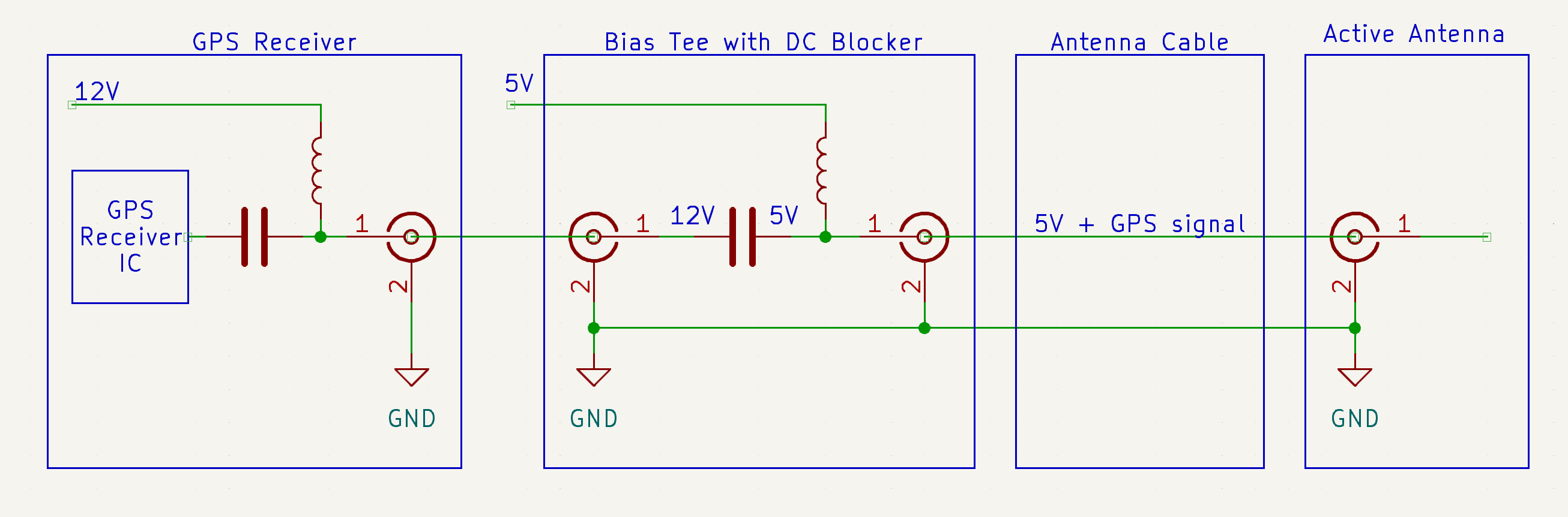
It is possible to make a 5V antenna work with a 12V GPS receiver by using a so-called “bias tee with DC blocker”.
 Click to enlarge
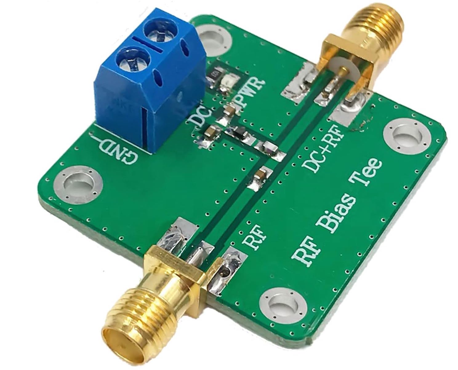
A bias tee with DC blocker removes the voltage from the 12V receiver and inserts a new one with yet another capacitor/inductor combo but requires an external power supply that provides the new voltage.
You can find them for as low as $12 on Amazon or less than half that on AliExpress. I’ve tried it, it works, but it’s not the topic of this blog post.
While researching GPS antennas in general, I stumbled on this web page with instructions on how to modify a 58532A so that it support 12V as well. And it’s super easy to do because the PCB already has the empty footprints.
The instructions only listed the values of the components, so in this blog post, I illustrate what to do, step by step.
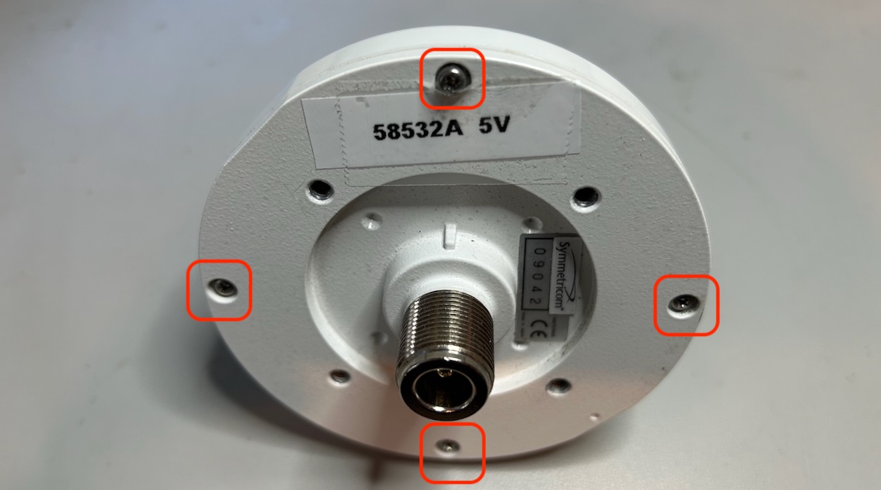
Opening up the 58532A
To remove the top cone, just remove 4 screws:
Then remove the 4 inner screws:
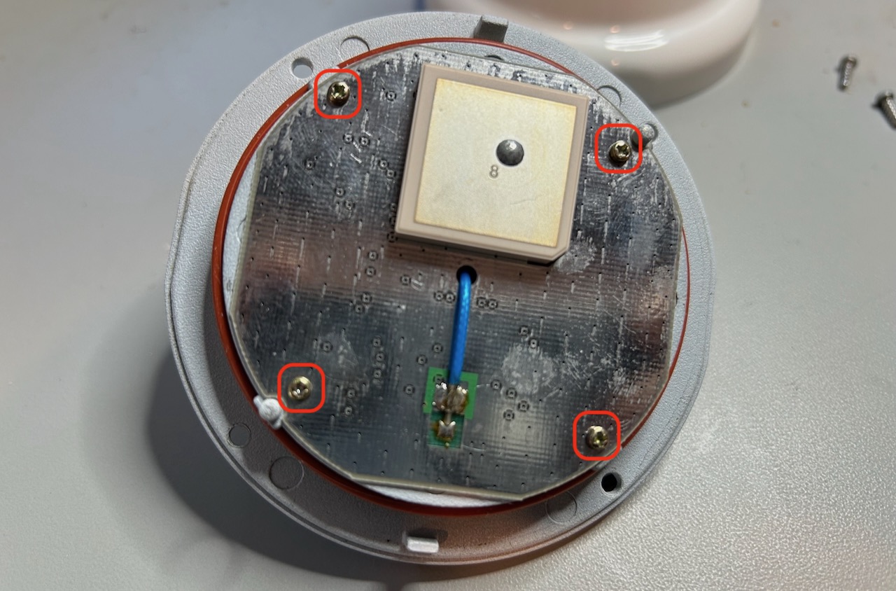
After this, you still can’t remove the PCB: the cable from the type N connector is preventing the PCB from coming off, so you need to desolder that cable as well.
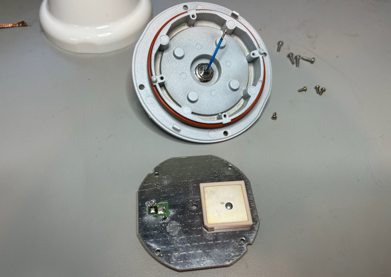
You can now see the backside of the PCB. It’s clearly different than the one that I showed earlier.
 Click to enlarge
Voltage Regulation
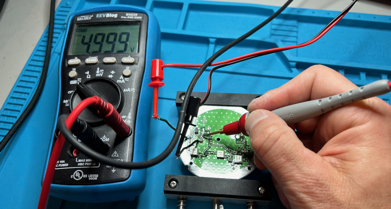
I soldered 2 wires to the ground and the cable input point, probed various voltages, and came up with a rough schematic:
 Click to enlarge
The signal path at the bottom goes from right to left, with a succession of 3 LNAs and a bunch of additional passive components for filtering that I didn’t draw.
The LNAs are powered by different voltages. From left to right, the cable goes through what looks like a small inductor that’s created by the PCB itself. There’s a TVS diode that protects against over voltage spikes such as those caused by lighting. I didn’t measure its value, but it’s supposed to be around 10V. After that, you get a resistive divider that brings down the voltages to 4.1V, 3.1V and 2.9V, which are feeding the LNAs.
Unlike the PCB of the different version that I showed earlier, there is no LDO in play at all, but there’s a footprint for it!
The voltage regulation section of the PCB looks like this:
 Click to enlarge
Here’s what the schematic looks like when we include the unpopulated components:
 Click to enlarge
The modification is straightforward:
- Replace the existing TVS diode with one that kicks in for voltages larger than 12V. Let’s say, 15V.
- Remove the first 47 Ohm resistor, R8, that creates a 4.1V voltage from a 5V voltage.
- Add an LDO that outputs 4.1V and that can sustain input voltages larger than 12V.
- Add capacitors before and after the LDO.
I used the following components:
| Compnent | Type |
|---|---|
| 15V unidirectional TVS diode | SMA6J15A-TR |
| 4.1V LDO | AP7380-41Y-13 |
| 10u/50V input cap | C1210C106K5RACTU |
| 10u/25V output cap | C1206C106K3RACTU |
Total cost: $2.46 on Mouser, if you ignore the $8 shipping cost. Better order this while ordering components for some other project. You can use the following Mouser project link to add the components to your shopping cart.
The result after the modification is below:
 Click to enlarge
Note the removal of the 47 Ohm resistor, and pay attention to the orientation of the TVS diode.
My soldering skills are a bit terrible, but I later found out that I was using lead-free solder with my soldering iron temperature set too low.
Result
After the mod, I remeasured the voltages before reassembly. They came out pretty much identical to what they were before, but this time for main inputs between 5V and 12V. When I supplied a 3.3V input, the output of the LDO was 3.22V. There’s some truth to the low drop-out name.
Time to reassemble the whole thing and check the result:
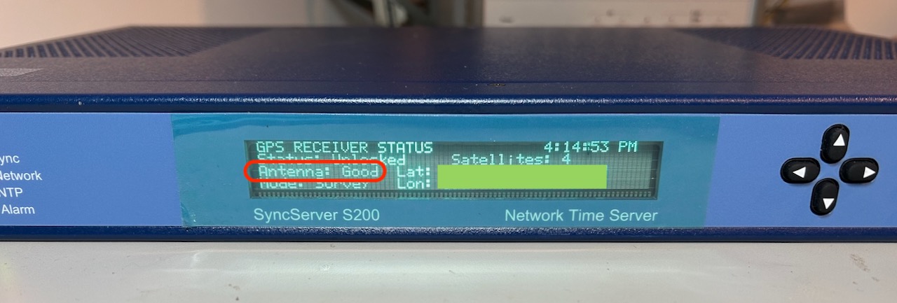
SUCCESS!
Instead of an ominous alarm, the antenna now reports as “Good” and satellites are detected. The S200 only sees 4 of them because the 58532A was inside the house. It’s obviously supposed to be on a roof somewhere.
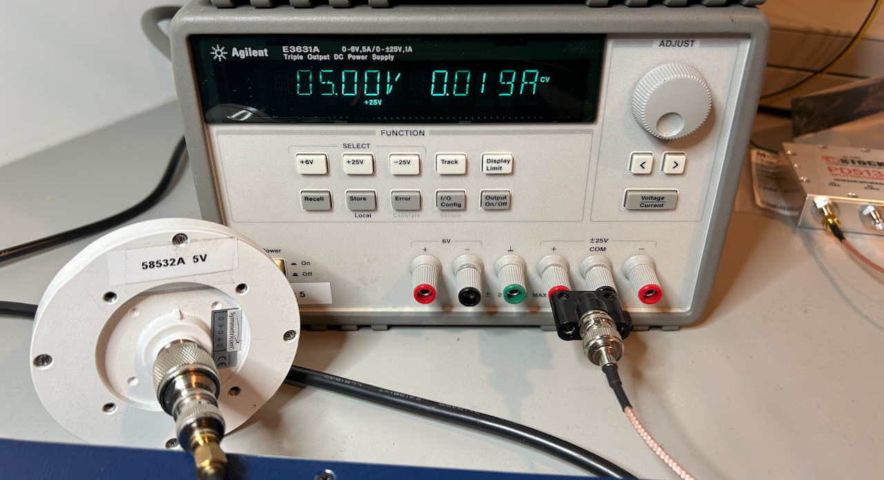
When connected to a 5V power supply, the antenna draws a current 19mA.
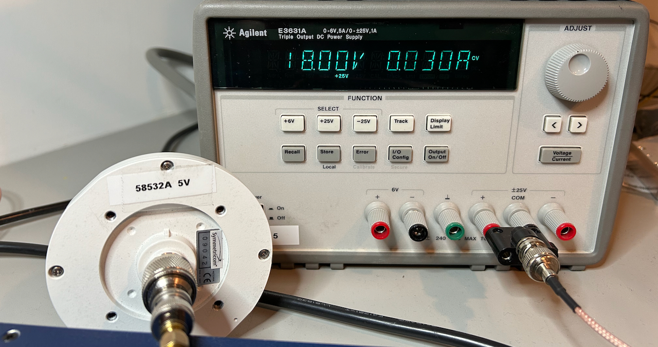
When I increased the supply voltage, the current stayed at 19mA until 17V, but at 18V it rose to 30mA: this is where the TVS protection diode kicked in. The LDO is rated for input voltages all the way to 24V.
Note to self: remove the “58532A 5V” tag from the antenna!
What about the other 58532A variant?
I don’t have the other 58532A variant, so even if it already has an LDO, it’s not clear if it can be used with 12V GPS receiver.
 Click to enlarge
The marking on the LDO is either “AE21” or “AF21”, and it’s either an SC-88A or SOT-25 package.
Google gives me the following options:
-
Ricoh RP109x Series - low noise 150mA LDO Regulator
There are both AE21 and AF21 variants for this, both with an output voltage of 2.1V. (The AF21 version has an extra auto-discharge transistor at the output.)
2.1V doesn’t match the 3.0V that’s marked on the PDF file, so it’s unlikely that this LDO is the one, but if it is then you can definitely not use it with a 12V supply because the input voltage is limited to 5.25V.
-
Diodes Inc - AP2112 600mA CMOS LDO REGULATOR WITH ENABLE
This one shows up as a hit for AF21. It has an output voltage of 3.3V and has a maximum input voltage of 6V.
It’s possible that it uses a different LDO that supports 12V, but I wouldn’t count on it.
References
-
[time-nuts] 58532A GPS antenna repair
Repair of broken 58532A. Includes a PDF with annotated pictures of the PCB. This one is a design that already contained an LDO, and the PCB is different than mine.
-
GPS antenna voltage and current requirements
58532A is listed, but the minimum required voltage, 3.8V, is quite a bit higher than the 3.0V that I saw on my bench. Since there are different versions, that’s not unexpected.
-
Symmetricom 58532A Antenna 12v Mod
12V modification on which this whole blog post is based.